JANOME MyLock 734D Owner's manual
- Category
- Sewing machines
- Type
- Owner's manual

INSTRUCTION BOOK
MODEL
MODÉLE
MODELO
LIBRO DE INSTRUCCIONES
MANUEL D’INSTRUCTIONS
734D

OPERATING INSTRUCTION:
For appliances with a polarized plug (one blade wider than the other):
To reduce the risk of electric shock, this plug is intended to fit in a polarized outlet only
one way.
If the plug does not fit fully in the outlet, reverse the plug.
If it still does not fit, contact a qualified electrician to install the proper outlet.
Do not modify the plug in any way.
Foot Controller YC-482J or TJC-150 for use with Sewing Machine MyLock 734D (for
U. S. A. market only)
NDICACIONES PARA EL FUNCIONAMIENTO:
Para aparatos eléctricos con enchufe polarizado (una cuchilla más ancha que la otra):
Para reducir el riesgo de un choque eléctrico, este enchufe está hecho para encajar en
un tomacorriente polarizado solamente de una manera.
Si el enchufe no encaja bien en el tomacorriente, invierta el enchufe.
Si aun no encaja, llame a un electricista calificado para que instale el tomacorriente
apropiado.
No modifique el enchufe de ninguna forma.
Pedal de Control YC-482J o TJC-150 para usar en la Máquina de Coser MyLock 734D
(para el mercado de los EE.UU. solamente)
NOTICE TECHNIQUE :
Pour les appareils avec fiche polarisée (une lame plus large que l’autre) : pour réduire le
risque de secousse électrique, cette fiche est conçue pour s’insérer dans une fiche polarisée
d’une seule manière.
Si la fiche ne s’insère pas complètement dans la prise, inverser la prise.
Si elle ne convient toujours pas, contacter un électricien qualifié pour poser une prise
appropriée.
Ne pas modifier la prise de quelque façon que ce soit.
Pédale de contrôle YC-482J ou TJC-150 pour l’emploi avec la machine à coudre
MyLock 734D (pour marché américain seulement).

1
IMPORTANT SAFETY
INSTRUCTIONS
Your sewing machine is designed and constructed only for HOUSEHOLD use.
Read all Instructions before using this appliance.
DANGER – To reduce the risk of electric shock:
1. An appliance should never be left unattended when plugged in. Always unplug this appliance from the
electrical outlet immediately after using and before cleaning.
2. Always unplug before relamping. Replace bulb with same type rated 15 Watts.
3. Do not reach for the appliance that has fallen into water. Unplug immediately.
4. Do not place or store appliance where it can fall or be pulled into a tub or sink. Do not place in or drop
into water or other liquid.
WARNING – To reduce the risk of burns, fire, electric shock,or injury to persons.
1. Do not allow to be used as a toy. Close attention is necessary when this appliance is used by or near
children.
2. Use this appliance only for its intended use as described in this manual.
Use only attachments recommended by the manufacturer as contained in this manual.
3. Never operate this appliance if it has a damaged cord or plug, if it is not working properly, if it has been
dropped or damaged, or dropped into water. Return the appliance to the nearest authorized dealer or
service center for examination, repair, electrical or mechanical adjustment.
4. Never operate the appliance with any air opening blocked. Keep ventilation openings of the sewing
machine and foot controller free from accumulation of lint, dust, and loose cloth.
5. Never drop or insert any object into any opening.
6. Do not use outdoors.
7. Do not operate where aerosol (spray) products are being used or where oxygen is being administered.
8. To disconnect, turn all controls to the off (“ 0 ”) position, then remove plug from outlet.
9. Do not unplug by pulling on cord. To unplug, grasp the plug, not the cord.
10. Keep fingers away from all moving parts. Special care is required around the sewing machine needle
and knives.
11. Always use the proper needle plate. The wrong plate can cause the needle to break.
12. Do not use bent needles.
13. Do not pull or push fabric while stitching. It may deflect the needle causing it to break.
14. Switch the sewing machine off (“ 0 ”) when making any adjustment in the needle area, such as
threading needle, changing needle, threading loopers, or changing presser foot, and the like.
15. Always unplug the sewing machine from the electrical outlet when removing covers, lubricating, or when
making any other adjustments mentioned in the instruction manual.
SAVE THESE INSTRUCTIONS
Page is loading ...
Page is loading ...

4
Do’s and Don’ts
1. Always be aware of the up-and-down movement of the needle and do not turn your attention
away from the machine while it is running.
2. When leaving the sewing machine unattended, the main switch of the machine must be
switched off or the plug must be removed from the socket-outlet.
3. When servicing the sewing machine, or when removing covers or changing lamps, the machine
must be disconnected from the power supply by removing the plug from the socket-outlet.
4. Do not place anything on the foot control, otherwise the machine will start inadvertently, or the
control or motor may burn out.
5. The maximum permissible power for the sewing lamp bulb is 15 watts.
6. When using your sewing machine for the first time, place a piece of waste fabric under the
presser foot and run the machine without thread for a few minutes. Wipe away any oil which
may have appeared.
Lo que debe y no debe hacer
1. Siempre esté atento al movimiento sube y baja de la aguja y no deje de ponerle atención a la
máquina mientras está funcionando.
2. Cuando no esté atendiendo a la máquina, debe desconectar el interruptor de la máquina, o
desenchufarla del tomacorriente.
3. Cuando esté dándole servicio a la máquina, o cuando retire las cubiertas o esté cambiando las
bombillas, debe desconectar la máquina de la energía eléctrica sacando el enchufe del
tomacorriente.
4. No coloque ningún objeto en el pedal de control, pues la máquina podría comenzar a funcionar
inadvertidamente, o el control o el motor podrán quemarse.
5. La intensidad máxima permitida de la bombilla de luz es 15 vatios.
6. Cuando use su máquina de coser por la primera vez, coloque un retazo de tela debajo del pie
prensatela y haga funcionar la máquina sin el hilo por unos minutos. Seque cualquier aceite que
pueda haber escurrido.
Recommandations et interdictions
1. Toujours être conscient du mouvement vers le haut et le bas de l’aiguille et toujours surveiller la
machine lorsqu’elle est en marche.
2. Lorsque la machine est laissée sans surveillance, l’interrupteur principal de la machine doit être éteint
ou la fiche doit être retirée de la douille/prise.
3. Lors des réparations de la machine à coudre ou lors du retrait des couvercles ou du changement des
ampoules, la machine doit être débranchée de la source d’alimentation en retirant la fiche de la
douille/prise.
4. Ne rien placer sur la pédale de contrôle, sinon la machine démarrera par inadvertance ou la pédale
ou le moteur pourront s’endommager.
5. La puissance maximale permise pour l’ampoule de couture est de 15 watts.
6. Lors de l’emploi de la machine à coudre pour la première fois, placer un morceau de tissu de rebut
sous le pied presseur et faire fonctionner la machine sans fil pendant quelques minutes.
Essuyer tout excédent d'huile qui pourrait être présent.

5
PREPARATION
Names of Parts .......................................................8
Attaching the Waste Chip Box .............................10
Storing the Accessory Box ...................................10
Standard Accessories...........................................10
Storing the Needle Threader.................................10
Connecting the Machine to the Power Supply......... 12
Controlling Sewing Speed ....................................12
For Your Safety ...............................................12
How to turn the Handwheel..................................14
Extension table .....................................................14
Opening and Closing the Looper Cover...............14
The Position of Thread Guide Bar ........................16
Attaching the Spool Holder Cap and Net................. 16
Changing Needle ..................................................18
How to use the Needle Holder .............................18
Raising or Lowering the Presser Foot ..................20
Removing the Presser Foot ..................................20
Attaching the Presser Foot ...................................20
Adjustment of Foot Pressure................................20
Adjustment of Stitch Length .................................22
Adjustment of Differential Feed Ratio...................22
How to Adjust..................................................22
To Deactivate the Upper Knife .............................24
To Activate the Upper Knife..................................24
Adjustment of Cutting Width ................................26
Adjustment of Needle Plate Setting Knob............28
Setting the Lower Looper Pre-Tension Setting
Slider and Changeable Thread Guide ..................30
Changing toTwo-Thread Serging .........................32
Threading the Machine .................................. 34~54
• Threading the Lower Looper ........................38
• Threading the Upper Looper........................44
• How to Thread only the Upper Looper ........46
• Threading the Needle on the Right ..............48
• How to Use the Needle Threader.................50
• Threading the Needle on the Left.................52
TEST STITCHING
Starting Sewing.....................................................56
Finishing Sewing...................................................56
Sewing Continuously ............................................56
How to Use Guide Lines.......................................56
Securing Ends.......................................................58
Thread Tension (4 threads) ............................ 60~62
Threading the Machine (3 threads).......................64
Thread Tension (3 threads) ...................................66
Threading the Machine (2 threads).......................68
Thread Tension (2 threads) ............................ 70~72
Thread and Needle Chart .....................................74
TABLE OF CONTENTS
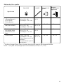
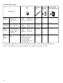
ROLLED HEMMING, PICOT EDGING AND
NARROW HEMMING
Machine Setting and Thread, Fabric and
Range of the Tension Dial.....................................77
Thread Tension .....................................................80
For Better Results.................................................82
DECORATIVE OVEREDGING
Thread and Fabric.................................................84
Machine Setting....................................................84
GATHERING
Thread and Fabric.................................................84
Machine Setting....................................................84
PIN TUCKING
Thread and Fabric.................................................86
Machine Setting....................................................86
Sewing ..................................................................86
CARE OF YOUR MACHINE
Replacing the Upper Knife....................................88
Cleaning Upper Knife Area ...................................88
Replacing the Light Bulb ......................................90
Cleaning the Feed Dog .........................................90
Oiling the Machine ................................................92
Carrying the Machine............................................92
Attachment Mounting Plate ..................................94
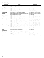
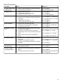
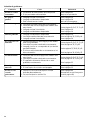
Troubleshooting....................................................96
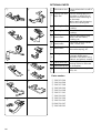
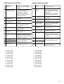
OPTIONAL PARTS......................................100
Page is loading ...
Page is loading ...

8
@7
@6
@5
@0
@2
@1
@3
@4
@8
@9
#5
#3
#0
#2
#1
#4
r
u
t
w
q
!9
!8
!7
!6
!5
!4
!3
o
!2
!1
!0
y
i
e
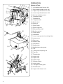
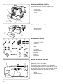
PREPARATION
Names of Parts
q Left needle thread tension dial
w Right needle thread tension dial
e Upper looper thread tension dial
r Lower looper thread tension dial
t Pressure adjusting screw
y Thread guide bar
u Thread guide
i Carrying handle
o Spool stand
!0 Spool pin
!1 Spool holder
!2 Stitch length dial
!3 Differential feed dial
!4 Machine socket
!5 Power switch
!6 Handwheel
!7 Lower looper pre-tension setting slider
!8 Looper cover
!9 Side cover
@0 Needle clamp
@1 Presser foot
@2 Needle plate
@3 Needle plate setting knob
@4 Tab
@5 Cutting width adjusting dial
@6 Free arm
@7 Thread cutter
@8 Lower knife
@9 Upper knife
#0 Upper looper
#1 Spreader holder
#2 Lower looper
#3 Changable thread guide
#4 Threader lever
#5 Upper knife release knob
Page is loading ...

10
r
e
w
q
w
q
qwer t
yuio
!0 !1 !2 !3
q
ew
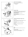
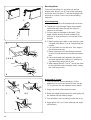
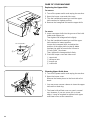
Attaching the Waste Chip Box
Insert the hook into groove on looper cover.
q
Groove
w Looper cover
e Waste chip box
r Hook
Storing the Accessory Box
Insert the accessory box into the waste chip box.
q
Waste chip box
w Accessory box
Standard Accessories
q Screwdriver (Large)
w Screwdriver (Small)
e Tweezers
r Set of needles No.11, No.14
t Nets
y Spool holder caps
u Lint brush
i Needle threader
o Oil
!0 Spreader
!1 Spanner
!2 Upper knife
!3 Attachment mounting plate
Storing the Needle Threader
You can store the attached needle threader inside of
the looper cover in the holder.
The holder is very convenient. You can use the
needle threader whenever you desired if it is stored
in the holder after using the needle threader. Push
the needle threader into the holder to store it.
q
Looper cover
w Holder
e Needle threader
Page is loading ...

12
q
w
e
r
t
y
q
3
2
1
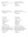
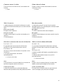
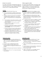
Connecting the Machine to the Power Supply
1. Turn off the power switch, and connect the
machine plug to the machine socket.
2. Connect the power supply plug to your power
supply.
3. Turn on the power switch.
Controlling Sewing Speed
Sewing speed can be varied by the speed controller.
The harder you press on the controller, the faster the
machine runs.
Step on the speed controller with the presser foot
lifter up, and practice controlling the speed.
For Your Safety:
* While in operation, always keep your eye on the
sewing area, and do not touch any moving parts
such as the thread take-up lever, loopers,
handwheel, needle or knives.
* Always disconnect the machine from the power
supply:
— when leaving the machine unattended.
— when attaching or removing parts.
— when threading or cleaning the machine.
* Do not place anything on the speed controller,
except when the machine is in use.
q
Power switch
w Machine plug
e Machine socket
r Power supply plug
t Power supply
y Speed controller
q Speed controller
Page is loading ...

14
q
q
q
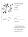
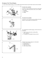
How to Turn the Handwheel
Always turn the handwheel toward you
(Counterclockwise).
q
Handwheel
Extension Table
The extension table provides added sewing surface
and can be easily removed for free arm sewing.
Detaching the table:
Pull the table away from the machine.
Attaching the table:
Push the extension table until it snaps into the
machine.
Opening and Closing the Looper Cover
To open: (A)
While pushing with the thumb to the right as far as it
will go, pull the looper cover toward you.
To close: (B)
Lift the looper cover and push it against the
machine.
The looper cover snaps into its position
automatically.
q
Looper cover
Note:
Always close looper cover when the machine is in
use.
Free arm sewing
The free arm is useful for sewing such tubular
garments as sleeves and pant legs.
Page is loading ...

16
q
r
e
w
r
e
w
q
w
q
1, 2
1
2
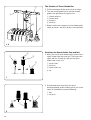
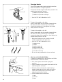
The Position of Thread Guide Bar
1. Pull the thread guide bar up as far as it will go.
2. Turn the thread guide bar so that the thread
guides are right above the spool pins.
q
Thread guide bar
w Thread guide
e Stoppers
r Spool pin
* Make sure the two stoppers on the thread guide
shaft, as shown, are set in at the correct position.
Attaching the Spool Holder Cap and Net
1. When you use a small thread spool, pull out the
spool holder from the spool pin. Then place the
spool with its slit side up, and put the spool
holder cap on top of it.
q
Spool holder
w Spool pin
e Spool holder cap
r Slit
2. If the thread slips down from the spool
during threading and/or sewing, put a net on the
spool as illustrated to prevent jamming.
q
Net
w Spool pin
Page is loading ...

18
q
w
r
e
y
q
t
w
w
e
q
w
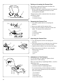
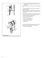
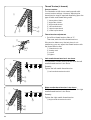
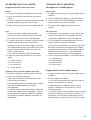
Changing Needle
Turn off the power switch and unplug the machine.
Raise the needle to its highest position.
Then loosen the left or right needle clamp screw for the
needle you are going to remove.
q
Needle clamp screw on the left
w Needle clamp screw on the right
* Use HA-1SP No.14 Needle or No.11.
To attach the needle on the right
Insert a new needle into the needle clamp with the
flat side to the back until the top of the needle
touches the stopper pin, then tighten the needle
clamp screw on the right.
To attach the needle on the left
Insert a new needle into the needle clamp with the
flat side to the back until the top of the needle
touches the edge of the needle bar, then tighten the
needle clamp screw on the left.
* When the needles are set correctly, the left
needle is higher than the right one.
* Use HA-1SP No.14 Needle or No.11.
q
Needle clamp
w Needle
e Needle stopper pin
r Edge of needle bar
t Needle clamp screws
y Flat side to the back
* Do not use any needle which is bent or blunt.
How to use the Needle Holder
To attach the needle easily, use the other end of the
needle threader to hold the needle.
1. Turn off the power switch and unplug the
machine.
2. Insert a needle into the needle holder with the flat
side facing back as shown.
3. Hold the stem and insert the needle into the
needle clamp and push it up as far as it will go.
Tighten the needle clamp screw firmly while
supporting the holder in place.
4. Pull the holder down to remove it.
q
Hole
w Flat side
e Stem
Page is loading ...

20
q
w
q
w
r
e
w
q
e
q
w
e
r
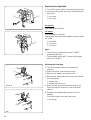
2.8 mm
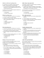
Removing the Presser Foot
1. Turn off the power switch and unplug the
machine.
2. Raise the needle and the presser foot.
3. Press the lever located on the back of the foot
holder. The presser foot will drop off.
q
Needle
w Presser foot lifter
e Foot holder
r Lever
Attaching the Presser Foot
1. Turn off the power switch and unplug the
machine.
2. Place the presser foot so that the pin on the foot
lies just under the groove of the foot holder.
3. Lower the foot holder to lock the foot into place.
4. Raise the presser foot lifter to check that the
presser foot is secure.
q
Foot holder
w Groove
e Pin
Adjustment of Foot Pressure
It is not necessary to adjust the presser foot’s
pressure for normal sewing.
When you sew heavy or lightweight fabrics, turn the
adjusting screw:
–– clockwise for heavyweight fabric.
–– counterclockwise for Iightweight fabric.
* For normal sewing, set the adjusting screw so
that it sits 2 mm below the top of the machine.
See the illustration.
q
To decrease
w To increase
e Adjusting screw
r Top of the machine
Raising or Lowering the Presser Foot
By raising or lowering the presser foot lifter, the
presser foot goes up or down.
* While in operation, keep the presser foot lowered
except when threading the machine or test
running without threads.
Thread tension will be released when the presser
foot lifter is raised.
q
Presser foot
w Presser foot lifter
Page is loading ...

22
q
e
w
e
w
q
q
w
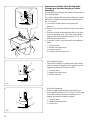
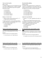
Adjustment of Stitch Length
To select stitch length, turn the dial.
The larger the number, the longer the stitch.
The stitch length can be adjusted from 1 to 5 mm.
Position “R” is for rolled and narrow hemmings.
q
Stitch length dial
w Setting mark
e Stitch length indicating window
Adjustment of Differential Feed Ratio
The differential feed ratio can be altered by turning
the dial.
The number in the window indicates the ratio
between the main and the sub feed motion.
1.0 indicates the neutral position.
q
Differential feed dial
w Setting mark
e Differential feed ratio indicating window
How to Adjust
• If the sewn fabric is stretched, turn the dial
counterclockwise (toward 2.2).
• If the sewn fabric is gathered, turn the dial
clockwise (toward 0.5).
q
Stretched
w Gathered
* When the stitch length dial is set between 1 to 4,
the maximum effective differential feed ratio is
2.2.
When the stitch length dial is set between 4 and
5, the maximum differential feed ratio will
automatically be set between 2.2 and 1.8.
Page is loading ...

24
q
w
q
w
q
w
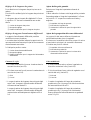
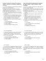
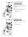
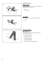
To Deactivate the Upper Knife
1.
Turn off the power switch and unplug the machine.
2. Open the looper cove.
3. Turn the handwheel toward you to bring the upper
looper to the most left position.
4. Pull out the upper knife release knob and slide it
down along the guide until it comes to its lowest
position.
5. Turn the handwheel to check if the upper knife is
deactivated.
6. Close the looper cover and side cover.
q
Upper knife release knob
w Upper Knife
To Activate the Upper Knife
1.
Turn off the power switch and unplug the machine.
2. Open the looper cover.
3. Turn the handwheel toward you to bring the upper
looper to the most left position.
4. Pull out the upper knife release knob and slide it
up along the guide until it comes to its highest
position.
5. Turn the handwheel to check if the upper knife is
activated.
6. Close the looper cover and side cover.
q
Upper knife release knob
w Upper knife
Page is loading ...

26
q
r
w
e
(A)
(B)
w
e
w
e
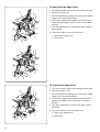
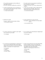
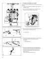
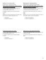
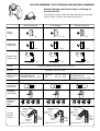
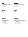
Adjustment of Cutting Width
When cutting width is too narrow or too wide against
seam width, adjust it as follows.
1. Turn off the power switch and unplug the
machine.
2. Remove the extension table and open the looper
cover.
3. Turn the cutting width adjusting dial to get
desired position of the lower knife.
q
Cutting width adjusting dial
w Lower knife
e Guide line on the needle plate
* The cutting width of this model can be
adjusted approximately 3.0 to 5.0 mm from the
right needle position depending upon your
sewing needs or the fabric being used.
(The cutting width should be adjusted to get
the same results as in drawing
.)
(A) When cutting width is too narrow.
Turn the cutting width adjusting dial clockwise.
Lower knife will move to right.
(B) When cutting width is too wide.
Turn the cutting width adjusting dial
counterclockwise.
Lower knife will move to left.
4. Close the looper cover and side cover.
5. Test stitch to check the cutting width.
6. Attach the extension table.
Page is loading ...

28
q
e
w
w
r
e
w
q
(A)
(B)
e
w
q
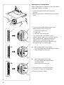
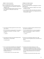
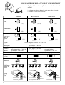
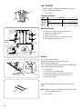
Adjustment of Needle Plate Setting Knob
(Changing to Standard Serging or Rolled
Hemming)
The needle plate setting knob adjusts the position of
the chaining finger.
The chaining finger will move back under the needle
plate when shifting the needle plate setting knob to
the “R” position.
1. Turn off the power switch and unplug the
machine.
2. Remove the extension table and open the looper
cover.
3. Push the cutting width adjusting dial to the right
as far as it will go, then, move the needle plate
setting knob to the standard position or “R” (for
rolled hemming) position.
4. Close the looper cover and attach the extension
table.
q
Chaining finger
w Needle plate setting knob
e Standard position
r Cutting width adjusting knob
(A) Standard Serging
* The chaining finger is located beside the needle
plate as shown in diagram (A) for guiding the flat
edge of the fabric for overlock sewing.
q
Chaining finger
w Needle plate setting knob
e Standard position
(B) Rolled Hemming
* Pull the needle plate setting knob toward you
from Standard position to "R" position, so the edge
of the fabric will be rolled for hemming, picot
edging and narrow hemming sewing.
q
Chaining finger
w Needle plate setting knob
e Guide line R
Page is loading ...

30
STD. R.H.
STD. R.H.
3/4
2
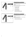
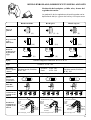
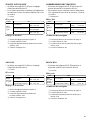
Setting the Lower Looper Pre-Tension
Setting Slider and Changeable Thread Guide
Standard serging(STD.)
Standard serging with 2, 3 or 4 threads
q Lower looper pre-tension setting slider
Rolled hemming(R.H.)
Rolled hemming with 2 or 3 threads
3/4 thread serging
Serging with 3 or 4 threads
w Changeable thread guide
2 thread serging
Serging with 2 threads
Change the setting depending on whether you’re
doing 3/4 thread serging or 2 thread serging.
3/4
2
Page is loading ...

32
e
w
q
(A)
r
t
i
o
u
y
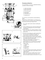
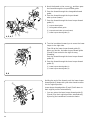
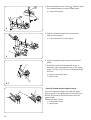
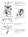
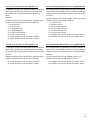
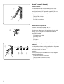
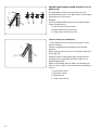
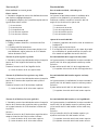
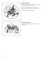
Changing to Two-Thread Serging
* In case of two-thread serging, use one needle thread and the lower looper thread. Remove other threads.
To attach the spreader
Put the tip of the spreader into the hole on the upper
looper, and slide the spreader down into the holder.
q Spreader
w Upper looper
e Holder
To remove the spreader
Pull tab A on the holder toward you lightly. Push the
bottom of the spreader up and pull it out.
For standard two-thread serging, set the machine as
illustrated.
r Lower looper pre-tension setting silder
(STD. position)
t Changeable thread guide (lower position)
Standard two-thread serging is as illustrated.
y Wrong side of fabric
u Needle thread
i Right side of fabric
o Lower looper thread
Page is loading ...

34
t
q
w
e
r
y
u
q
12
34
w
e
t
r
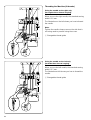
Threading the Machine
The left illustration shows the completed threading
conditions of the four threads.
q
Lower looper thread
w Upper looper thread
e Right needle thread
r Left needle thread
t Thread guide
y Thread guide plate
u Threading chart
The machine is pre-threaded to make threading
easier.
Tie the end of a new thread to one of the pre-set
threads, and pull it to draw the new thread through
the machine, following the steps below.
* Turn off the power switch before threading the
machine.
1. Pull the threads from the spools and draw them
through the thread guides, then tie the thread
ends together.
2. Raise the presser foot, draw the threads until the
knots are coming out from under the back of the
presser foot.
3. However, stop drawing the needle threads when
the knots reach just before the needle eye.
Cut the knots and thread the needle eye.
4. Before starting sewing, clear the needle threads
from under the presser foot to make sure they are
not caught below the needle plate.
(Draw the needle threads in the direction A.)
Then pull out the threads to the back
approximately 10 cm (4˝) away from the presser
foot. Lower the presser foot, and you are now
ready to sew.
q
Thread guide
w Needle
e Needle thread
r Presser foot
t Needle plate
• For re-threading the machine easily, start from the
lower looper, upper looper, right needle and left
needle threads.
Make sure to clear the needle threads out from
below the needle plate and draw them to the
back and under the presser foot about 10 cm (4˝).
Page is loading ...

36
1
2
3
q
q
4
e
r
e
y
t
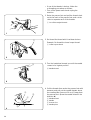
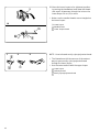
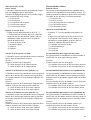
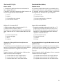
• If one of the threads is broken, follow the
re-threading procedure as follows:
* Turn off the power switch and unplug the
machine.
1. Raise the presser foot and pull the thread chain
out to the back of the presser foot, and cut the
chain to separate each of the threads.
q
Cut off the tangled threads.
2. Re-thread the thread which had been broken.
Example: Re-thread the lower looper thread.
w
Lower looper thread
3. Turn the handwheel toward you until the needle
comes to its highest position.
e Needle thread
4. Pull the threads from under the presser foot with
tweezers and pull out the needle threads above
the needle plate. Draw out 10 cm (4˝) away from
the presser foot. (Draw the needle thread in the
direction A)
e
Needle thread
r Needle
t Presser foot
y Needle plate
Page is loading ...
Page is loading ...
Page is loading ...
Page is loading ...
Page is loading ...
Page is loading ...
Page is loading ...
Page is loading ...
Page is loading ...
Page is loading ...
Page is loading ...
Page is loading ...
Page is loading ...
Page is loading ...
Page is loading ...
Page is loading ...
Page is loading ...
Page is loading ...
Page is loading ...
Page is loading ...
Page is loading ...
Page is loading ...
Page is loading ...
Page is loading ...
Page is loading ...
Page is loading ...
Page is loading ...
Page is loading ...
Page is loading ...
Page is loading ...
Page is loading ...
Page is loading ...
Page is loading ...
Page is loading ...
Page is loading ...
Page is loading ...
Page is loading ...
Page is loading ...
Page is loading ...
Page is loading ...
Page is loading ...
Page is loading ...
Page is loading ...
Page is loading ...
Page is loading ...
Page is loading ...
Page is loading ...
Page is loading ...
Page is loading ...
Page is loading ...
Page is loading ...
Page is loading ...
Page is loading ...
Page is loading ...
Page is loading ...
Page is loading ...
Page is loading ...
Page is loading ...
Page is loading ...
Page is loading ...
Page is loading ...
Page is loading ...
Page is loading ...
Page is loading ...
Page is loading ...
-
 1
1
-
 2
2
-
 3
3
-
 4
4
-
 5
5
-
 6
6
-
 7
7
-
 8
8
-
 9
9
-
 10
10
-
 11
11
-
 12
12
-
 13
13
-
 14
14
-
 15
15
-
 16
16
-
 17
17
-
 18
18
-
 19
19
-
 20
20
-
 21
21
-
 22
22
-
 23
23
-
 24
24
-
 25
25
-
 26
26
-
 27
27
-
 28
28
-
 29
29
-
 30
30
-
 31
31
-
 32
32
-
 33
33
-
 34
34
-
 35
35
-
 36
36
-
 37
37
-
 38
38
-
 39
39
-
 40
40
-
 41
41
-
 42
42
-
 43
43
-
 44
44
-
 45
45
-
 46
46
-
 47
47
-
 48
48
-
 49
49
-
 50
50
-
 51
51
-
 52
52
-
 53
53
-
 54
54
-
 55
55
-
 56
56
-
 57
57
-
 58
58
-
 59
59
-
 60
60
-
 61
61
-
 62
62
-
 63
63
-
 64
64
-
 65
65
-
 66
66
-
 67
67
-
 68
68
-
 69
69
-
 70
70
-
 71
71
-
 72
72
-
 73
73
-
 74
74
-
 75
75
-
 76
76
-
 77
77
-
 78
78
-
 79
79
-
 80
80
-
 81
81
-
 82
82
-
 83
83
-
 84
84
-
 85
85
-
 86
86
-
 87
87
-
 88
88
-
 89
89
-
 90
90
-
 91
91
-
 92
92
-
 93
93
-
 94
94
-
 95
95
-
 96
96
-
 97
97
-
 98
98
-
 99
99
-
 100
100
-
 101
101
-
 102
102
-
 103
103


JANOME MyLock 734D Owner's manual
- Category
- Sewing machines
- Type
- Owner's manual
Ask a question and I''ll find the answer in the document
Finding information in a document is now easier with AI
in other languages
Related papers
-
JANOME MyLock 644D Owner's manual
-
-
JANOME Magnolia 7034D Owner's manual
-
-
-
-
-
JANOME 3434D Owner's manual
-
-
Other documents
-
 Euro-Pro 534DX Owner's manual
-
Brother 2340CV User guide
-
ELNA 664 PRO Owner's manual
-
Brother 3234DT User guide
-
-
-
-
Brother COMPACT OVERLOCK MACHINE User manual
-
-
