
PNRQ20RBL, PNRQ21RBN and PNRQ21RRB are
Tested and Certified to NSF/ANSI Standards 58
and 42 and CSA B483.1. For the reduction of
the claims specified, see the Performance Data
Sheet.
GEAppliances.com
34-8710-7653-4 49-50263-5 02-13 GE
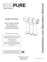
Reverse Osmosis
Filtration System
PNRQ20RBL
PNRQ21RBN
PNRQ21RRB
Owner’s Manual
and Installation
Safety Instructions
Safety Instructions ................2, 3
Specification Guidelines ...........4-6
Operating Instructions
About the RO System ................7
Installation Instructions
Tools and Materials Required ........8
Before Beginning Installation ........9
Mounting System Installation .......10
Feed Water Supply .............11, 12
Tubing and Flow Restrictor
Installation .......................14
Faucet Assembly ...............15, 16
Battery Installation .................16
Filtration Drain Connection .....17, 18
Storage Tank and Startup ..........18
Care and Cleaning
Prefilter, Postfilter and
RO Cartridge Replacement .........19
Sanitization ........................20
Water Test Kit ......................20
Troubleshooting Tips ......21, 22
Consumer Support
Consumer Support ........Back Cover
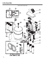
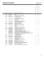
Parts List/Catalog ..............24, 25
Warranty ..........................26
Manuel d’utilisation
et d’installation
Manual del propietario
y instalación
La section française commence à la page 27
Osmose Inversée
Système de Filtration
La sección en español empieza en la página 53
Ósmosis Inversa
Sistema de Filtración
Write the model and serial
numbers here:
Model # __________________
Serial # ___________________
You can find them on the bracket.
C
US

Be sure the water supply conforms with the Specification
Guidelines. If the water supply conditions are unknown, contact
your municipal water company or your local health department
for a list of contaminants in your area and a list of laboratories
certified by your state to analyze drinking water.
WARNING To reduce the risk associated with
choking:
'RQRWDOORZFKLOGUHQXQGHU\HDUVRIDJHWRKDYHDFFHVVWR
small parts during the installation of this product.
WARNING To reduce the risk associated with the
ingestion of contaminants:
'RQRWXVHZLWKZDWHUWKDWLVPLFURELRORJLFDOO\XQVDIHRURIXQNQRZQ
quality without adequate disinfection before or after the system.
Systems certified for cyst reduction may be used on disinfected water
that may contain filterable cysts. EPA Establishment #10350-MN-005.
WARNING To reduce the risk associated with
hazardous voltage due to an installer drilling through existing
electric wiring or water pipes in the area of installation:
Do not install near electric wiring or piping which may be in path
of a drilling tool when selecting the position to mount the filter
bracket.
WARNING To reduce the risk of physical injury:
'HSUHVVXUL]HV\VWHPDVVKRZQLQPDQXDOSULRUWRFDUWULGJH
removal.
WARNING To reduce the risk of physical injury due to
hydro-pneumatic tank rupture:
Do not install if water pressure exceeds 120 psi (827 kPa). If your
water pressure exceeds 80 psi (552 kPa), you should install a
pressure limiting valve. Contact a plumbing professional if you
are uncertain how to check your water pressure.
Do not install where water hammer conditions may occur.
If water hammer conditions exist you should install a water
hammer arrester. Contact a plumbing professional if you are
uncertain how to check for this condition.
:KHUHDEDFNIORZSUHYHQWLRQGHYLFHLVLQVWDOOHGRQDZDWHU
system, a device for controlling pressure due to thermal
expansion should be installed.
WARNING To reduce the risk associated with
irritation from Sodium Metabisulphite during installation:
6RGLXP0HWDELVXOSKLWH&$6LVXVHGLQD
preservative solution within the reverse osmosis membrane.
'RQRWSXWWKLVV\VWHPLQWRVHUYLFHEHIRUHWKH52WDQNLVIOXVKHGDV
specified in the installation instrucitons. Wear eye and face protection
during installation.
To request an MSDS relating to this product call 203-238-8965
or visit the web at
http://solutions.3m.com/wps/portal/3m/en_us/
msds (click MSDS search). For emergencies, call 800-364-3577
or 651-737-6501 (24 hours).
WARNING To reduce the risk associated with
ingesting of water contaminated with sanitizer:
$IWHULQVWDOODWLRQVDQLWL]HU0867EHIOXVKHGIURPWKHV\VWHP
before first use as directed within the installation instructions.
This system has been tested for the treatment of water containing
pentavalent arsenic (also known as As(V), As(+5) or arsenate) at
concentrations of 0.050 mg/L or less. This system reduces pentavalent
arsenic, but may not remove other forms of arsenic. This system is to be
used on water supplies containing a detectable free chlorine residual
or on water supplies that have been demonstrated to contain only
pentavalent arsenic. Treatment with chloramine (combined chlorine)
is not sufficient to ensure complete conversion of trivalent arsenic
to pentavalent arsenic. Please see the Arsenic Facts section of the
Performance Data Sheet for further information.
This reverse osmosis system contains a replaceable component
critical to efficiency of the system. Replacement of the reverse
osmosis component should be with one of identical specifications,
as defined by the manufacturer, to assure the same efficiency and
contaminant reduction performance.
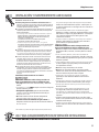
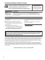
SAFETY PRECAUTIONS
SAFETY INFORMATION
IMPORTANT SAFETY INFORMATION.
READ ALL INSTRUCTIONS BEFORE USING.
2
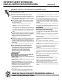
Read, understand, and follow all safety information contained in these instructions prior to installation and use of the GE Reverse Osmosis
systems. Retain these instructions for future reference.
Intended use:
The GE Reverse Osmosis systems are intended for use in filtering potable water in Residential applications, and have not been evaluated
for other uses. The system is typically installed at the point of use, and must be installed as specified in the installation instructions. Contact
a plumbing professional if you are uncertain how to install.
This is the safety alert symbol. It is used to alert you to potential personal injury hazards. Obey all safety
messages that follow this symbol to avoid possible injury or death.
WARNING indicates a potentially hazardous situation which, if not avoided, could result in death or
serious injury.
&$87,21LQGLFDWHVDSRWHQWLDOO\KD]DUGRXVVLWXDWLRQZKLFKLIQRWDYRLGHGPD\UHVXOWLQPLQRUWR
moderate injury.
&$87,21XVHGZLWKRXWWKHVDIHW\DOHUWV\PEROLQGLFDWHVDSRWHQWLDOO\KD]DUGRXVVLWXDWLRQZKLFKLIQRW
avoided, may result property damage.
WARNING
&$87,21
&$87,21

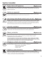
SAVE THESE INSTRUCTIONS
READ AND FOLLOW THIS SAFETY INFORMATION CAREFULLY.
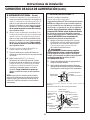
Extended non-use of the Reverse Osmosis system.
If the system has not been used for one week or more,
open the RO water faucet and allow the system to
drain. Close the RO water faucet and allow the system
to regenerate the water supply.
Recommended installation is under the sink. However,
the unit can be installed in a remote location, up to 20
feet away from the sink.
+RZHYHUDGGLWLRQDOPDWHULDOVZLOOEHUHTXLUHG
See parts list to obtain additional materials
from GE.
/RFDWLQJWKHWDQNRQDEDVHPHQWIORRUZLWKWKHIDXFHW
at a first floor sink may result in some loss of flow rate
DQGFDSDFLW\DSSUR[LPDWHO\,QVWDOOLQJDVHFRQG
tank will improve this performance. An RVKIT can be
used.
If Reverse Osmosis system is connected to a refrigerator
icemaker, a special icemaker connection kit is required
(RVKIT). Do not use copper tubing for the connection
between the Reverse Osmosis system and the
refrigerator.
Sanitize upon installation of the Reverse Osmosis system
and after servicing inner parts, including replacement
of prefilter, postfilter and Reverse Osmosis cartridge. It is
important to have clean hands while handling inner parts
of the system.
See the Sanitizing the Reverse Osmosis System section.
This Reverse Osmosis system contains a replaceable
treatment component critical for effective reduction of
total dissolved solids. This product water shall be tested
periodically to verify that the system is performing
satisfactorily. See the The Water Test Kit section.
BE SURE TO FOLLOW ALL APPLICABLE STATE
AND LOCAL CODES.
CAUTION:
To reduce the risk associated with
property damage due to water leakage:
Read and follow these instruction before installation and
use of this system.
,QVWDOODWLRQDQGXVHMUST comply with all state and local
plumbing codes.
Protect from freezing, remove filter cartridge when
temperatures are expected to drop below 40° F (4.4° C).
Do not install systems in areas where ambient
temperatures may go above 110° F (43.3° C).
'RQRWLQVWDOORQKRWZDWHUVXSSO\OLQHV7KHPD[LPXP
operating water temperature of this filter system is
100°F (37.8°C).
'RQRWLQVWDOOLIZDWHUSUHVVXUHH[FHHGVSVL
kPa). If your water pressure exceeds 80 psi (552 kPa),
you should install a pressure limiting valve. Contact a
plumbing professional if you are uncertain how to check
your water pressure.
'RQRWLQVWDOOZKHUHZDWHUKDPPHUFRQGLWLRQVPD\
occur. If water hammer conditions exist, you should
install a water hammer arrester. Contact a plumbing
professional if you are uncertain how to check for this
condition.
:KHUHDEDFNIORZSUHYHQWLRQGHYLFHLVLQVWDOOHGRQD
water system, a device for controlling pressure due to
thermal expansion should be installed.
CAUTION:
To reduce the risk associated with
property damage due to water leakage:
'RQRWXVHDWRUFKRURWKHUKLJKWHPSHUDWXUHVRXUFHV
near filter system, cartridges, plastic fittings or plastic
plumbing.
2QSODVWLFILWWLQJVQHYHUXVHSLSHVHDODQWRUSLSHGRSH
8VH37)(WKUHDGWDSHRQO\SLSHGRSHSURSHUWLHVPD\
deteriorate plastic.
7DNHFDUHZKHQXVLQJSOLHUVRUSLSHZUHQFKHVWRWLJKWHQ
plastic fittings, as damage may occur if over tightening
occurs.
'RQRWLQVWDOOLQGLUHFWVXQOLJKWRURXWGRRUV
'RQRWLQVWDOOQHDUZDWHUSLSHVZKLFKZLOOEHLQSDWKRI
a drilling tool when selecting the position to mount the
bracket.
0RXQWILOWHULQVXFKDSRVLWLRQDVWRSUHYHQWLWIURP
being struck by other items used in the area of
installation.
(QVXUHWKDWWKHORFDWLRQDQGIDVWHQHUVZLOOVXSSRUWWKH
weight of the system when installed and full of water.
(QVXUHDOOWXELQJDQGILWWLQJVDUHVHFXUHDQGIUHHRI
leaks.
'RQRWLQVWDOOXQLWLIDQ\FROOHWVSDUWVDQGRQSDJH
DUHPLVVLQJ&RQWDFW86
800.663.6060 (Canada-English),
800.362-3869 (Canada-French) if collets are missing
from any fittings to obtain replacements.
5HSODFHWKHGLVSRVDEOHSUHDQGSRVWILOWHUFDUWULGJHV
every 6 months, at the rated capacity or sooner if a
noticeable reduction in flow rate occurs.
5HSODFHWKHGLVSRVDEOH52FDUWULGJHHYHU\PRQWKV
or sooner if a noticeable reduction in filtration efficiency
occurs.
PROPER INSTALLATION AND MAINTENANCE
This Reverse Osmosis system must be properly installed and located in accordance with the Installation
Instructions before it is used.
IMPORTANT SAFETY INFORMATION.
READ ALL INSTRUCTIONS BEFORE USING.
GEAppliances.com
3

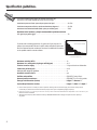
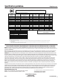
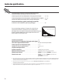
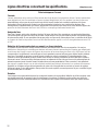
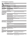
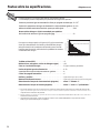
Specification guidelines.
The system makes a good supply of drinking water each day.
How much it will make depends primarily on these things…
WATER SOFTENER RECOMMENDED
INCOMING WATER HARDNESS (GPG)
60
50
40
30
2010
8
6
7
5
5
Water Softener
not required
Maximum turbidity (NTU) ...............................................<2
Maximum iron, manganese, hydrogen sulfide (ppm) .....................<0.1
Chlorine in water supply ................................................2.0 ppm Maximum Allowable
b
Feed water pH limits (pH) ...............................................4–10
6WRUDJHWDQNFDSDFLW\³JDOORQV .........................................4
c
Automatic shutoff control ..............................................yes
Prefilter and postfilter . . . . . . . . . . . . . . . . . . . . . . . . . . . . . . . . . . . . . . . . . . . . . . . . . .(FQROPF) Carbon Block
Reverse Osmosis membrane ...........................................(FQROMF) Thin Film Polyamide
Storage Tank Dimension (inches) ........................................height 15” diameter 11”
System Body Dimension (inches) ........................................height 11” width 10.5” depth 4”
)HHGZDWHUSUHVVXUHOLPLWV³SRXQGVSHUVTXDUHLQFKSVL .....................40–120
a
)HHGZDWHUWHPSHUDWXUHOLPLWV³PLQLPXPPD[LPXPGHJUHHV) ..............40–100
0D[LPXP7RWDO'LVVROYHG6ROLGV7'6³SDUWVSHUPLOOLRQSSP ...............2000
Maximum water hardness @ 6.9 pH recommended to optimize membrane
OLIH³JUDLQVSHUJDOORQJSJ .....................................................10
For water with hardness greater than 10 grains (at 6.9 pH), the use of a
softener is recommended. Failure to install a water softener will reduce the
life of the Reverse Osmosis membrane. See chart for additional information
on the possible need for a water softener.
a. If house water pressure is over 80 psi, install a pressure reducing valve in the water supply line. If house water pressure
is under 40 psi, install a Reverse Osmosis booster pump (contact your local plumbing supply company).
E 5HGXFHGPD[LPXPRISSPE\WKH5HYHUVH2VPRVLVSUHILOWHU5(*8/$50$,17(1$1&(,65(48,5('&KORULQHZLOOGHVWUR\WKH
Reverse Osmosis membrane.
c. Theoretical tank capacity. When tested according to NSF/ANSI Standard 58 at 50 psig inlet pressure, tank capacity is
2.3 gallons.
4

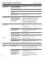
Specification guidelines.
GEAppliances.com
5
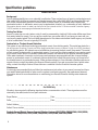
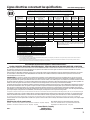
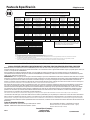
Contaminant Reduction Determined by NSF testing.
Contaminant
Reduction
(1)
Average Influent
NSF specified Challenge
Concentration
Avg %
Reduction
Average Product
Water
Concentration
Max
Permissible
Product Water
Concentration
NSF Reduction
Requirements
NSF Test
Report
Arsenic (pentavlent)
0.051 mg/L 0.050 mg/L ± 10% 98.0% 0.001 mg/L 0.010 mg/L N/A J-00082158
Asbestos
180 fibers/L
10
7
to 10
8
fibers/L;
fibers greater than 10μm
99.9% < 1 fiber/L NA 99% J-00077915
Barium
10 mg/L 10 mg/L ± 10% 96.5% 0.341 mg/L 2.00 mg/L N/A J-00077916
Cadmium
0.030 mg/L 0.03 mg/L ± 10% 97.6% 0.0007 mg/L 0.005 mg/L N/A J-00082186
Chromium (Hex.)
0.31 mg/L
0.3 mg/L ± 10% (added as
hexavalent)
97.5% 0.008 mg/l 0.1 mg/L N/A J-00077916
Chromium (Tri.)
0.33 mg/L 0.3 mg/L ± 10% (added as triavalent) 96.5% 0.01 mg/l 0.1 mg/L N/A J-00077916
Copper
3.2mg/L 3.0 mg/L + 10% 97.5% 0.008 mg/L 1.3 mg/L N/A J-00077913
Cyst
73,000 cysts/L Minimum 50,000 cysts/L 99.99% 5 cyst/L N/A ≥99.95% J-00077914
Lead
0.15 mg/L 0.15 mg/L +
10% 97.6% 0.003 mg/L 0.010 mg/L N/A J-00082186
Radium 226/228
25 pCi/L 25 pCi/L ± 10% 80.0% 5 pCi/L 5 pCi/L N/A J-00077916
Selenium
0.1 mg/L
0.10 mg/L ± 10% (added as ½
selenite and ½ selenate)
98.0% 0.002 mg/L 0.05 mg/L N/A J-00077911
TDS
760 mg/L 750 mg/L + 40 mg/L 91.6% 64 mg/L 187 mg/L N/A J-00077940
Turbidity
(2)
138 NTU 11 ± 1 NTU 99.9% 0.13 NTU 0.5 NTU N/A J-00077914
Chlorine Taste and Odor
2.1 mg/L 2.0 mg/L ± 10% 96.1% 0.08 mg/L N/A ≥ 50% J-00076398
Nominal Particulate Class
III
, ≥ 5 μm to < 15 μm
119,333 pts/mL At least 10,000 particles/mL 99.2% 948 pts/mL N/A ≥85% J-00082586
Operating Specifications
Inlet Pressure 40-120 psig (2.8-7.0 kg/cm
2
)
Inlet Temperature
40-100 F° (5-38° C)
Maximum TDS Level 2000 mg/L
Maximum Hardness @ 6.9pH 10 grains per gal. (171 mg/L)
Maximum Chlorine 2.0 mg/L
pH Range 4 – 10
Daily Production Rate 13.16 GPD (49.8 L/day)
Efficiency Rating
(3)
12.75%
Recovery Rating
(4)
23.14%
Notes:
(1) Tested by NSF International per NSF/ANSI Standard 58 or NSF/ANSI Standard 42.
(2) NTU is Nephelometric Turbidity Units
(3) Efficiency rating means the percentage of the influent water to the system that is available to the user as reverse osmosis treated water under operating conditions that approximate
typical daily usage.
(4) Recovery rating means the percentage of influent water to the membrane portion of the system that is available to the user as reverse osmosis treated water when the system is
operated without a storage tank or when the storage tank is bypassed.
System tested and certified by NSF International against NSF/ANSI Standard 42 and against NSF/ANSI Standard 58
for the reduction of substances as listed below according to Standard 42 and 58.
The concentration of the indicated substances in water entering
the system was reduced to a concentration less than or equal to
the permissible limit for water leaving the system as specified in
NSF/ANSI Standard 58.
Performance Data Sheet Profile™ Reverse Osmosis System
Models: PNRQ20FBL, PNRQ20FWW, PNRQ20FBB,PNRQ20FCC, PNRQ21LBN, PNRQ21LRB, PNRQ20RBL,PNRQ21RBN, and PNRQ21RRB.
Notice: This system has been tested according to NSF/ANSI 58 for reduction of the substances listed below. The concentration of the indicated
substances in water entering the system was reduced to a concentration less than or equal to the permissible limit for water leaving the system, as
specified in NSF/ANSI 58.
Before purchasing a water treatment unit, it is recommended that you have your water supply tested to determine your actual water treatment
needs. The NSF/ANSI 58 testing were performed under standard testing conditions, actual performance mayvary with local water conditions.
WARNING: Do not use with water that is microbiologically unsafe or with water of unknown quality without adequate disinfection before or after
the system. Systems certified for cyst reduction may be used on disinfected water that may contain filterable cysts. This system is to be used for
arsenic reduction only on chlorinated water supplies containing detectable residual free chlorine at the system inlet. Water systems using an in-line
chlorinator should provide a one-minute chlorine contact time before the RO system. See Arsenic Fact Sheet for additional details.
This reverse osmosis system contains a carbon pre-filter to help protect the reverse osmosis membrane from deterioration that is induced by
chlorine in the supply water. This reverse osmosis system contains replaceable treatment components critical to the efficiency of the system.
Replacement of the membrane component should be with one of identical specifications, as defined by the manufacturer, to assure the same
efficiency and contaminant reduction performance. The product water should be tested periodically to verify that the system is performing
satisfactorily. Consult the owner’s manual for further information on installation, operating instructions, component replacement, and product
warranty.
This system has been tested for the treatment of water containing pentavalent arsenic (also known as As (V), As (+5), or arsenate) at concentrations
of 0.050 mg/L or less. This system reduces pentavalent arsenic, but may not remove other forms of arsenic. This system is to be used on water
supplies containing a detectable free chlorine residual at the system inlet or on water supplies that have been demonstrated to contain only
pentavalent arsenic. Treatment with chloramine (combined chlorine) is not sufficient to ensure complete conversion of trivalent arsenic to
pentavalent arsenic. Please see the Arsenic Facts section of Performance Data Sheet for further information.
Estimated Replacement Costs
FQROPF – Pre- and Post-Filters carbon elements: $34.99 - $39.99
FQROMF – Reverse Osmosis Membrane: $69.99 - $79.99
General Electric Company
Appliance Park
Louisville, KY 40225
P/N 101052 0310
)RUUHSODFHPHQWSDUWVFDOOWROOIUHH86
800.663.6060 (Canada-English),
800.361.3869 (Canada-French).
Rev 7

Arsenic Fact Sheet
Background
Arsenic (abbreviated As) can occur naturally in well water. There are two forms of arsenic: pentavalent arsenic
(also called As(V), As(+5), and arsenate), and trivalent arsenic (also called As(III), AS(+3), and arsenite). Although
both forms are potentially harmful to human health, trivalent arsenic is considered more harmful than
pentavalent arsenic. In well water, arsenic may be pentavalent, trivalent, or a combination of both. Additional
LQIRUPDWLRQDERXWDUVHQLFLQZDWHUFDQEHIRXQGRQWKH,QWHUQHWDWWKH86(QYLURQPHQWDO3URWHFWLRQ$JHQF\
86(3$ZHEVLWHDWZZZHSDJRYVDIHZDWHUDUVHQLFKWPO
Testing Your Water
Arsenic in water has no color, taste or odor. It must be measured by a lab test. Public water utilities must have
their water tested for arsenic. You can get the results from your water utility. If you have your own well, you
can have the water tested. The local health department or the state environmental health agency can provide
a list of certified labs. The cost is typically $15 to $30.
Pentavalent vs. Trivalent Arsenic Reduction
This system is very effective at reducing pentavalent arsenic from drinking water. This model was tested in a
ODEDQGSURYHQWRUHGXFHSDUWVSHUELOOLRQSSESHQWDYDOHQWDUVHQLFWREHORZSSEWKH86(3$VWDQGDUG
for safe drinking water. RO systems are not as effective at removing trivalent arsenic from water. This model
will not convert trivalent arsenic to pentavalent arsenic. If you have free chlorine residual in your water supply,
any trivalent arsenic will be converted to pentavalent arsenic and reduced by this Reverse Osmosis system.
Other water treatment chemicals, such as ozone and potassium permanganate will also change trivalent
arsenic to pentavalent arsenic. A combined chlorine residual (also called chloramine) may not convert all of
the trivalent arsenic to pentavalent arsenic. Water systems using an in-line chlorinator should provide a one-
minute chlorine contact time before the Reverse Osmosis system. If you get your water from a public water
utility, contact the utility to find out if free chlorine or combined chlorine is used in the water system.
Maintenance
It is strongly recommended that you follow the maintenance instructions in your owner’s manual and have
your water tested periodically to make sure the system is performing properly. See replacement element
information above for recommendations on maintaining your Reverse Osmosis drinking water treatment
system.
For IOWA Only
All sales in Iowa require the following signature before consummation of sale. These signatures must be
retained by the seller/renter for two years minimum.
Buyer/Renter ____________________________________Date _______________________________________
Seller ___________________________________________Date _______________________________________
Seller’s Address _______________________________________________________________________________
Seller’s Phone number _________________________________________________________________________
Product: General Electric Reverse Osmosis Filtration Systems: PNRQ20FBL, PNRQ20FWW, PNRQ20FBB,
PNRQ20FCC, PNRQ21LBN, PNRQ21LRB, PNRQ20RBL, PNRQ21RBN, and PNRQ21RRB.
6
Specification guidelines.

How the Reverse Osmosis System Works
Reverse Osmosis reduces Total Dissolved Solids (TDS) and organic matter from water by diffusing it
through a special membrane (see
Performance Data Sheet). The membrane separates minerals and impurities from the water and they
are flushed to the drain. For the
reduction of the claims specified, see Performance Data Sheet. High quality product water goes directly to the drinking water faucet or
to the storage tank. The system makes a good supply of drinking water each day. How much it makes depends on the feed water supply
pressure, temperature and quality.
The prefilter and postfilter are replaceable cartridges. The carbon prefilter reduces chlorine while also filtering sediments. The postfilter reduces
any other undesirable tastes and odors before you use the water.
These systems include an electronic faucet assembly with a prefilter and postfilter change reminder, Reverse Osmosis membrane change
reminder and a status okay reminder.
The prefilter and postfilter change reminder will flash amber after six months have passed or 900 gallons have been used. When this occurs, it
is time to replace these cartridges and sanitize the system.
The membrane change reminder flashes amber when the TDS monitor in the system has measured the amount of impurities removed is less
WKDQ:KHQWKLVRFFXUVLWLVWLPHWRUHSODFHWKLV5HYHUVH2VPRVLVPHPEUDQHFDUWULGJHDQGVDQLWL]HWKHV\VWHP
Finally, a green flashing light will indicate the system is functioning properly.
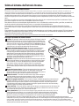
Description of the Reverse Osmosis System
1
Prefilter³Water from the cold supply pipe is directed to the prefilter
cartridge.
The prefilter is a replaceable sediment cartridge containing activated
carbon. The prefilter reduces chlorine taste and odor in the feed water because
CHLORINE DESTROYS THE REVERSE OSMOSIS MEMBRANE. Filtered, clean,
chlorine-reduced water flows from the prefilter to the Reverse Osmosis cartridge.
2
Reverse Osmosis Cartridge³The middle cartridge includes a tightly wound,
special membrane. Water is forced through the cartridge where the membrane
reduces the dissolved solids and organic matter. For the reduction of the claims
specified, see Performance Data Sheet. High quality product water exits the
Reverse Osmosis cartridge and goes to the storage tank. Reject water, with the
dissolved solids and organic matter, leaves the cartridge and is discharged to
WKHGUDLQWKURXJKø” tubing.
3
Postfilter³After leaving the storage area, but before going to the system
faucet, product water goes to the postfilter cartridge. The postfilter is also a
replaceable sediment cartridge that contains activated carbon. Any
remaining tastes, odors or sediments are reduced from product water by
the postfilter. Clean, high quality drinking water flows through the tubing and
to the system faucet.
4
Storage Tank³The storage area holds up to 2-1/2 gallons of product water.
A diaphragm inside the tank keeps water pressurized, when the tank is full, for
fast flow to the faucet when drinking water is needed.
5
Check Valve³The check valve prevents a backward flow of product water
from the storage tank. A backward flow could cause the Reverse Osmosis
membrane to rupture.
6
Automatic Shutoff Assembly³To conserve water, the drinking water system
has an automatic shutoff. When the storage tank has filled to capacity and the
drinking water faucet is closed, pressure closes the shutoff. Water flow to the
Reverse Osmosis housing is shut off until drinking water is used again, and pressure drops in the Reverse
Osmosis system.
7
Flow Control³The flow control regulates the flow of water through the Reverse Osmosis cartridge at
the required rate to produce high quality water. The control is located in the 1/4” drain line exiting off the
manifold.
8
Faucet and Electronics³The countertop faucet dispenses filtered drinking water when opened. It
has a hand-operated lever, with variable flow adjustment. You can keep the faucet open by removing
your hand from the lever once water is flowing.
To comply with plumbing codes, an air gap is built into
the faucet drain water connection.
The electronic faucet provides a six month timer and flow monitor to remind you when it is time to
replace your prefilter and postfilter. Replace these when the amber filter light flashes. The faucet also
provides an amber RO light indicating when the Reverse Osmosis cartridge is no longer filtering out at
OHDVWRIWKH7'65HSODFHWKLVFDUWULGJHZKHQWKLVDPEHUOLJKWIODVKHV7KHJUHHQIODVKLQJOLJKWZLOO
indicate the system is functioning properly.
About the reverse osmosis system.
GEAppliances.com
7

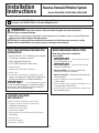
Installation
Reverse Osmosis Filtration System
Instructions
Models PNRQ20RBL, PNRQ21RBN, PNRQ21RRB
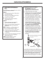
BEFORE BEGINNING INSTALLATION
Read these instructions completely
and carefully.
IMPORTANT ³6DYHWKHVHLQVWUXFWLRQV
for local inspector’s use.
IMPORTANT ³2EVHUYHDOOJRYHUQLQJ
codes and ordinances.
Note to Installer – Be sure to leave these
instructions with the Consumer.
Note to Consumer – Keep these instructions for
future reference.
3URSHULQVWDOODWLRQLVWKHUHVSRQVLELOLW\
of the installer.
3URGXFWIDLOXUHGXHWRLPSURSHULQVWDOODWLRQLVQRW
covered under the Warranty.
$VKXWRIIYDOYHPXVWEHDYDLODEOHRUDGGHGQHDU
the installation point.
CONTENTS INCLUDED
WITH PRODUCT
5HYHUVH2VPRVLV$VVHPEO\DQG7XELQJ
3URGXFW/LWHUDWXUH2ZQHU·V0DQXDODQG
Installation Instructions)
3HUIRUPDQFH'DWD6KHHW
)HHG:DWHU$GDSWHU
)DXFHW$VVHPEO\ZLWK(OHFWURQLF%DVH0RQLWRU
and Tubing
6WRUDJH7DQN
'UDLQ/LQH$GDSWHU
6DQLWDWLRQ&DQLVWHUV
8
WARNING: Read entire manual. Failure to follow all guides and rules could cause
personal injury or property damage.
&KHFNZLWK\RXUVWDWHDQGRUORFDOSXEOLFZRUNVGHSDUWPHQWIRUSOXPELQJFRGHV<RXPXVWIROORZWKHLU
guides as you install the Water Filtration system.
NOTE: Failure to comply with these installation instructions will void the product warranty, and the
installer will be responsible for any service, repair or damages caused thereby.
TOOLS AND MATERIALS REQUIRED FOR
INSTALLATION
Electric drill and 1-1/2” Drill Bit (type as required)
if mounting is needed for faucet.
Two (2) Adjustable Wrenches
1/16” Drill Bit (optional for pilot holes)
7DSH0HDVXUH
3KLOOLSVDQG)ODW%ODGH6FUHZGULYHUV
8WLOLW\.QLIH
,I\RXUPDLQZDWHUOLQHLVDULJLGSLSH\RXZLOO
require a compression fitting and possible other
plumbing hardware to complete installation.
IMPORTANT ³7RDYRLGGDPDJLQJWKHVLQN
consult a qualified plumber or installer for drilling
procedures. Special drill bits may be needed for
stone, porcelain or stainless steel.
Questions? Call 800.952.5039 or visit our Website at: GEAppliances.com
In Canada, call 1.800.561.3344 or visit www.GEAppliances.ca

Installation Instructions
Things to Check Before Beginning Installation
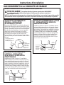
FEED WATER
The water supply to the undercounter Reverse
Osmosis system must have the qualities listed in
the specifications. Municipal water supplies most
often will have these qualities. Well water may need
FRQGLWLRQLQJ³KDYHWKHZDWHUWHVWHGE\DZDWHU
analysis laboratory and get their recommendations
for treatment.
IMPORTANT ³For water with a hardness
greater than 10 grains (at 6.9 pH), the use of a
softener is recommended. Failure to install a softener
will reduce the life of the Reverse Osmosis cartridge.
FILTRATION DRAIN CONNECTION
A suitable drain point and air gap (check your state
and/or local codes) are needed for reject water
from the Reverse Osmosis membrane cartridge.
BASEMENT INSTALLATION
If installing in a basement, leave enough tubing in
place during installation to be able to move unit
to floor for ease at servicing and making filter/
membrane changes. Additional tubing and fittings
required.
NOTE: See parts list on page 26 for optional parts
that may be required for a basement installation.
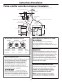
RO FAUCET
The RO product water faucet installs on the sink
or on the countertop next to the sink. Often, it
is installed in an existing sink spray attachment
hole or a hole may be drilled. Space is required
underneath for tubing to and from the faucet,
and for securing the faucet in place. All faucet
connections are done on or above the sink or
countertop.
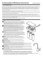
Sink
p-trap
Hot Cold
Disposer
1/4” drain
tube (black)
3/8” outlet tube (blue banded)
1/4” inlet tube
(yellow banded)
Reverse osmosis system
3/8” storage
tank tube (red
banded)
11” dia.
10-1/2”
15”
11 ”
3/8” drain tube (black)
RO product water faucet mounted through sink or countertop
Feed water adapter
Prefilter PostfilterMembrane
1/4” yellow
banded inlet
from supply
valve
1/4” black
tube to
faucet
3/8” red
banded tube
to storage
tank
3/8” blue
banded
tube to
faucet
9
7”
TUBING/FILTER DETAIL

Installation Instructions
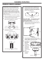
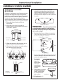
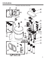
REVERSE OSMOSIS ASSEMBLY
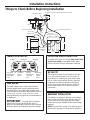
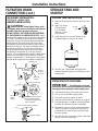
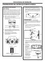
MOUNTING SYSTEM INSTALLATION
Choose a location under the sink to mount the
system. Location should be easily accessible,
with adequate clearance between the bottom
of the filter cartridges and the floor or bottom of
the cabinet for removal of filter cartridges. Allow
enough space on either side of the system for the
tubing connections.
1. Remove the prefilter and postfilter cartridges.
2. Remove the assembly cover by unlocking the
four tabs on the cover from the system.
3. 8VHDIODWKHDGVFUHZGULYHUWRZRUNIURPOHIWWR
right from the underside of the system.
4. 8VHWKHLFRQVRQWKHERWWRPRIWKHV\VWHPIRU
screwdriver positioning.
5. Hold the Reverse Osmosis assembly up to
the wall surface where you wish to install it.
Mark location for screws. There should be a
minimum of 17 inches from the marks to the
bottom of the cabinet floor.
IMPORTANT ³ Do not get dirt or debris
inside the assembly area. Use only to mark
mounting hole locations.
6. Install screws to the wall, leaving a 3/16-inch
clearance between the head of the screw and
wall (drill pilot holes if needed).
7. Hang the Reverse Osmosis assembly on the
screws. Tighten or loosen the screws as desired
until the system is secure on the wall.
8. To install the cover, line up the front
tabs on the
cover with the
openings
in the system.
9. Snap the cover
in place; the
tabs will flex,
allowing the
cover to snap in
place.
10. Remove the
membrane
cartridge.
Screw locations
17”
7”
Screws
Screw
3/16”
Wall
Screwdriver positioning
Screwdriver
System opening
Tab
Prefilter Postfilter
To removeTo remove
To remove
Membrane
10

Installation Instructions
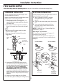
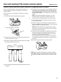
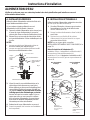
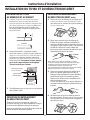
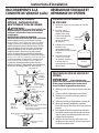
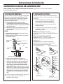
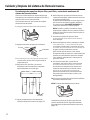
FEED WATER SUPPLY
B. OPTIONAL INSTALLATION 1
8WLOL]LQJH[LVWLQJNLWFKHQVLQNZDWHUVXSSO\YDOYH$
and removable faucet tubing (B).
1. Refer to illustration below to complete
assembly depending on supply valve
size (A).
2. Close the cold water supply valve (A) under the
sink.
3. 8QVFUHZWKHIOH[LEOHWXELQJOLQH%IURP
the supply valve (A) that connects to the
COLD water riser.
NOTE: For rigid pipe, see D. Optional Rigid Pipe
Installation on page 11.
Note Adapter (C) orientation:
µLQVWDOODWLRQ³5RXQGHGHQGRIDGDSWHU&
connects to supply valve (A).
µLQVWDOODWLRQ³5RXQGHGHQGRIDGDSWHU&
connects to coupling (D), then to existing faucet
tubing (B).
Check and comply with local plumbing codes as you plan, then install a cold feed water supply fitting.
11
For 3/8” Plumbing For 1/2” Plumbing
(B) Faucet
tubing line (not
included)
(D)
Coupling
(C)
Adapter
(F) Inlet valve
(A) Cold water
supply valve
(not included)
(B) Faucet
tubing line (not
included)
(A) Cold water
supply valve
(not included)
(D)
Coupling
(C) Adapter
(G) Gasket
(G)
Gasket
(H) Ferrule
(F) Inlet valve
(I) Nut
(G) Gasket
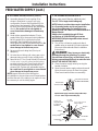
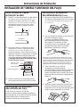
A. PREFERRED INSTALLATION
8WLOL]LQJH[LVWLQJNLWFKHQVLQNZDWHUVXSSO\YDOYH
and removable faucet tubing.
A typical connection using the included water supply
fitting is shown in the illustration below.
1. Close the water shut-off valve that is
immediately in front of the supply tube and
open the faucets to drain water from the sink
cold water pipe.
2. Remove the nut that connects the cold water
faucet to the supply tube. Some water may spill
out.
NOTES:
Be sure to turn off the water supply and open
a faucet to drain the pipe.
Make sure the gasket is installed in the water
supply fitting.
3.
Hand-tighten the water supply fitting onto the
cold water faucet. Be sure the gasket, as shown,
is in place before final assembly. Finish tightening
with an adjustable wrench. Be careful not to
over tighten or cross-thread, since damage to
the threads can occur. Make sure the 1/4” quick
connection is not against a wall that causes the
supply tubing connection to bend. A quarter turn to
tighten or loosen the adapter may be necessary to
avoid this.
4. Reconnect faucet tubing line to the fitting.
5. Install tubing. (See Installing the Tubing section.)
Cold
Water
Faucet
Stud
Cold
Water Pipe
Water Supply Fitting
1/4” Tubing to
Water Filter Inlet
Cold Water Shut-Off
Gasket
Fig. 1

Installation Instructions
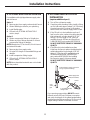
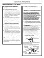
FEED WATER SUPPLY (cont.)
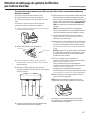
C. OPTIONAL INSTALLATION 2
Where codes permit (Requires additional parts)
*For 1/2” OD or larger metal tubing only.
NOTE: Codes in certain states require installation
by a licensed plumber and do not permit the
use of the saddle valve. For installation, use
plumbing code 248-CMR of the Commonwealth of
Massachusetts.
Saddle valve is available through GE Parts
and Services at 1.800.626.2002, part number
WS15X10023. Self-piercing saddle valves are not
recommended.
1. Turn off the cold water supply and attach
saddle valve as required by product selection.
(Be sure to follow manufacturer’s Installation
Instructions.)
DANGER: Many homes are electrically
grounded through the plumbing. To protect
yourself from serious injury or fatal shock, use a
battery-powered hand drill only to make the hole.
DO NOT USE AN ELECTRIC DRILL.
2. Close the water supply valve by turning the
handle clockwise.
3. Open the main water supply valve and several
house faucets to purge air from the system.
Close faucets when water runs smoothly.
Snug valve into bracket
(DO NOT OVER TIGHTEN)
Some threads
should be visible
Optional water supply connection (using saddle valve)*
Pre-drill
1/4” hole
6HDO³PDNHVXUHWKH
seal is in place
Clamp X
1XW³QRW
required if holes
in clamp are
threaded
Valve
Handle
Tubing adapter
Washer
Compression
nut
Í
Clamp Z
8VHWRFRQQHFWWKHWXELQJ
*For 1/2” OD or larger metal tubing only.
12
B.
OPTIONAL INSTALLATION 1 (CONT.)
4. Assemble adapter (C) and coupling (D) as
shown in illustration on page 9, per your
configuration. Ensure that the gasket (G) is in
place before final assembly. Start installation
by hand; then finish tightening with adjustable
wrench. Be careful not to over tighten or
cross-thread since damage to threads may
occur.
5. Hand-tighten assembled adapter (C) onto
supply valve (A) for the proper size installation.
Be sure gasket (G) is in place before final
assembly. Start installation by hand, then
finish tightening with an adjustable wrench. Be
careful not to over tighten or cross-thread
since damage to threads may occur.
6. Reconnect faucet tubing line (B) to top of
adapter (C).
7. Cut wire ties on tubing coils, using care not to
damage tubes or parts if using a utility knife.
8. Remove the 1/2” nut (I) and ferrule (H) from end
RILQOHWYDOYH8VLQJWKH\HOORZEDQGHGWXELQJ
provided, place the nut (I) and ferrule (H) onto
the tubing and install onto inlet valve (F) as
shown at left. Tighten with adjustable wrench.
Be careful not to over tighten or cross-thread
since damage to threads may occur.
NOTE: Inspect the ends of the tubing prior
to installation to be sure there are no imperfections
and that the end of the tubing is cut square. It may
be necessary to cut the tubing again.
Rubber gasket

Installation Instructions
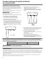
E. OPTIONAL REMOTE LOCATION
INSTALLATION
(requires additional part)
1. Turn off the cold water supply.
2. Complying with plumbing codes, install a fitting
on the cold water pipe to adapt 1/4” OD tubing.
A typical connection is shown in illustration
below. Make sure a water supply valve is used.
3. If the RO unit is to be installed more than 6
feet from the valve, replace the yellow banded
inlet tubing with a longer length of GE 1/4”
tubing. A 33-foot length of 1/4” tubing is
available through GE Parts and Services at
1.800.626.2002, part number WS07X10018.
DO NOT SUBSTITUTE TUBING OF UNKNOWN
QUALITY.
4. If the RO unit is to be installed more than
6 feet from the faucet, replace the blue banded
outlet tubing with a longer length of GE 3/8”
tubing. A 33-foot length is available through
GE Parts and Services at 1.800.626.2002,
part number WS07X10019. See Installing
the Faucet on page 14 for more details.
DO NOT SUBSTITUTE TUBING OF UNKNOWN
QUALITY.
If you are using copper tubing, DO NOT connect
it directly onto the RO unit. Purchase a connector
and use a short length of the yellow banded tubing
provided to make final connection to RO. Do not use
copper tubing to attach to icemaker or faucet.
Cold
water
pipe
1/4” (yellow banded)
tubing to inlet
Insert (not included)
Ferrule
Water supply valve
To RO
Preferred water supply connection
(using compression fitting)
13
D. OPTIONAL RIGID PIPE INSTALLATION
For installation with rigid pipe between supply valve
and sink faucet.
Option 1
1. Remove pipe from supply valve and sink faucet.
2. Obtain flexible pipe sized to your plumbing.
3. Install flexible pipe.
4.
GO back to B. OPTIONAL INSTALLATION 1
section, step 4.
Option 2
1. Obtain compression fittings to fit rigid pipe.
2. Obtain any other fittings required to connect
compression fittings to adapter.
NOTE: Adapter has 1/2-inch and 3/8-inch internal
and external threads.
3. Remove pipe from supply valve.
4. Cut pipe to fit length of assembled fittings and
adapter.
5. Install compression fitting to pipe.
6. GO back
to B. OPTIONAL INSTALLATION 1
section
, step 4.
NOTE: Above described materials are not included
with the product.

Installation Instructions
14
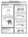
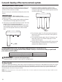
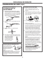
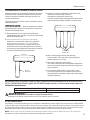
TUBING AND FLOW RESTRICTOR INSTALLATION
INSTALLING THE TUBING
TO TANK AND FAUCET
1. Measure 3/4” from the end of each remaining
piece of tubing (faucet end and inlet end) and
mark with a pencil. (Check for roundness,
smoothness, cuts, nicks, flat spots and sharp
edges).
2. Push the tubing firmly into each fitting on the
manifold until the line is flush with the fitting
collar. (If the tubing is removed, re-cut the end,
measure, mark and re-insert). Tubing must be
fully inserted to avoid leaks. To remove tubing:
depress and hold red or blue collet; pull tubing
out to remove.
3. Pull out slightly on tubing to ensure a good
seal.
3/4”
(19 mm)
INCORRECT
3
4
"
Engagement
3/4”
(3/8” tubing)
Red or Blue Collet
(DO NOT REMOVE)
Insertion line
Insert tubing
FLOW RESTRICTOR
REPLACEMENT PROCEDURE
(cont.)
1. Remove drain line tubing by pushing up on the
drain line collet with one hand (1) and removing
the drain line with the other hand (2).
2. Once the drain line has been removed from
the system base, grasp the end of the flow
restrictor and pull it straight out from the tube*.
If the restrictor is difficult to remove by hand, a
pair of pliers may be used to grip the end of the
restrictor to aid in removal from the tubing.
* In some instances, the restrictor may slide out of the drain
tubing as it is removed from the drain line port. If, after
removing the drain line as described in step 1, the restrictor
is no longer in the end of the tubing, check the drain line port.
Remove the restrictor from the port and proceed to step 3.
3. Take new restrictor and slide it back into the drain
tubing. Insert the restrictor by hand only. Do not
use pliers to insert. Make sure to insert restrictor
all the way into the tubing. Failure to do so could
result in improper operation of the RO system.
4. Reinsert drain line tubing in system base. Tug
lightly on the tubing to ensure that the collet is
engaged and has a proper grip on the tubing.
FLOW RESTRICTOR
REPLACEMENT PROCEDURE
Each time the Reverse Osmosis cartridge is
changed, you will need to replace the flow
restrictor in the drain line as well.
Be sure to wash your hands before handling inner
parts of the system.
1
2

Installation Instructions
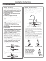
FAUCET ASSEMBLY
INSTALL THE FAUCET (CONT.)
5. Tighten the toggle screw until the base is firmly
in place and does not wobble or turn.
6. Push the 3/8” blue tube up to connect it to the
fitting on the bottom of the faucet body. It should
go in about 3/4”. Pull tube slightly to make sure it
is secure.
7. Push the faucet body down into the faucet base
and turn the faucet 1/8 of a turn counterclockwise
until it stops into place.
NOTE: You can install the faucet so the handle is
on the right or the left side.
If you want the faucet handle on the right, position
the handle on the front-right side of the base before
turning 1/8 of a turn counterclockwise.
If you want the faucet handle on the left, position
the handle on the rear-left side of the base before
turning 1/8 of a turn counterclockwise.
8.Locate the hole at the rear
of the base. Insert the set
screw and begin to tighten
by hand. Finish tightening
with the Allen wrench
provided in the packet.
DO NOT OVER TIGHTEN.
Faucet body
Faucet base
Sink
Gasket
Toggle screw
3/8” Black tube
INSTALL THE FAUCET
Be sure there is room underneath and above
the sink to make the needed connections. Before
starting, make sure there is sufficient room for the
faucet base and unit. Select one of the following
places to install the faucet:
A. In an existing sink spray attachment or soap
dispenser hole.
B. In a hole to be drilled in the sink top.
C. In a hole to be drilled in the countertop, next to
the sink.
NOTES:
%HVXUHWKHIDXFHWEDVHZLOOILWIODWDJDLQVWWKH
surface at the selected location so the bottom
gasket between the base and surface area will
seal.
0DNHVXUHWROHDYHHQRXJKFOHDUDQFH
at the back of the faucet in case you need
to remove it.
Installation Steps (refer to illustration below
for clarification)
1. If drilling is needed, make a 1
1
ø2” diameter hole.
Be sure to use the proper procedure for drilling
stone, porcelain or stainless steel. Special
drill bits may be needed. Consult a qualified
plumber for the proper procedure.
NOTE: When drilling in stainless steel, the edges
may be sharp and could puncture the tube. Be
careful to not cut yourself or damage the tube.
2. Remove the faucet body and base by turning the
base counterclockwise.
3. Push the 1/4” black tube and the 3/8” black tube
onto the correct barb fittings on the faucet base.
Push the 3/8” blue tube and the black power
cord (telephone wire) through the base.
4. Align the gasket to cover the hole completely.
Then place the toggle screw on the base into the
hole.
Faucet base
Sink
Gasket
Toggle screw
1/4” Black tube
Faucet base
1/4” Barb fitting
1/4” Black tube
3/8” Barb fitting
3/8” Black tube
3/8” Blue tube
3/8” Blue tube
Mounting screw
Faucet Faucet
Faucet handle on the RIGHT Faucet handle on the LEFT
15
Black power cord
Black power cord

Installation Instructions
FAUCET ASSEMBLY (cont.)
INSTALL THE BATTERY
1. Remove the lens cover from the faucet base.
Grip it from both sides and pull forward.
2. Install one CR2032 3V battery with the
´µVLGH83LQWRWKHEDWWHU\WUD\6OLGHWKH
battery tray completely back into the base.
3. Each light will illuminate in sequence twice.
The OK (green) light or Filter (amber) light may
stay on for a few extra seconds. If you want to
reinitiate the start-up sequence, remove the
battery for 90 seconds so the electronics can
fully reset; then put the battery back in.
4. The OK (green) light will normally flash one time
per second when dispensing water. If the system
needs service, the Filter or R.O. (amber) lights will
flash one time per second while dispensing and
will randomly flash when not in use.
NOTE: For lights to change between OK and
R.O., the system must detect a change in the
filtering process for 25 consecutive seconds.
For example, if the system was showing that
service was needed, it will take 25 seconds of
consecutive filtering for the system to confirm
the correct service changes were made.
FOR FILTER CHANGE: Replace the battery
when changing the filter. Remove the used
battery and wait 90 seconds before installing
the new battery to ensure the proper
electronics are reset for the next 6 months.
OPTIONAL ONE-PERSON
FAUCET TUBING INSTALLATION
1. From under the sink, gather the 1/4” drain line
(black), 3/8” drain line (black) and 3/8” outlet
tube (blue banded) in one hand with the drain
tubes the same length and the outlet tube offset
approximately 6 inches.
2. Wrap a rubber band around all 3 tubes.
3. Insert a typical No. 2 pencil through the rubber
band location.
4. Rotate the pencil down until it is in line with
the tubing and push up through the mounting
hole. Release the grip on the pencil and the
tubes will remain in position for easier faucet
connection.
POWER CORD INSTALLATION
Connect power cord from
faucet to union outlet
from the Reverse Osmosis
Assembly.
NOTE: If extension cord
is required for a remote
location, this extension
phone cable must be 6 conductor wire and connectors;
typical 4 conductor will not work.
16
Faucet base
Lens cover
Battery “+” side up

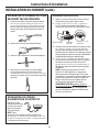
Installation Instructions
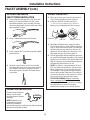
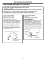
FILTRATION DRAIN CONNECTION
PREFERRED INSTALLATION:
237,21$³
BASEMENT ACCESS INSTALLATION
Route the drain line DIRECTLY from the Reverse
Osmosis system to a standpipe in the basement,
bypassing the air gap provided in the faucet. The
air gap installation is left to the discretion of the
installer. The drain line may also be routed to a
floor drain or washtub, provided that the air gap is
maintained. Special air gap fittings are available to
connect the drain line to the top of the standpipe.
Check and comply with local plumbing codes as you plan.
CAUTION: The options detailed below are the ONLY approved installation configurations.
Do not use any drain saddle device.
NOTE: Failure to follow these Installation Instructions will void the warranty, and the installer
will be responsible for any service, repair or damages caused thereby.
17
Drain line from the Reverse Osmosis system
1”
1” minimum
air gap must be
maintained
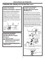
PREFERRED INSTALLATION:
237,21%³'5<9(17('
P-TRAP INSTALLATION
Install a separate dry-vented p-trap under the sink
to be used exclusively for the Reserve Osmosis
drain line. A dry-vented p-trap is a p-trap that has
its own vent/stack. Attach the drain line adapter to
the p-trap and secure it with the slip joint nut and
ZDVKHUDVVKRZQ7KHGUDLQOLQH0867EHURXWHG
through the air gap provided in the RO water faucet.
Reverse
Osmosis
drain line
Optional disposer
PREFERRED INSTALLATION:
237,21&³:(79(17('375$3
INSTALLATION
Install a p-trap under the sink to be used exclusively for
the Reverse Osmosis drain line. A wet-vented p-trap is
a p-trap that shares a common vent/stack. Attach the
drain line adapter to the p-trap and secure it with the
VOLSMRLQWQXWDQGZDVKHUDVVKRZQ7KHGUDLQOLQH0867
be routed through the air gap provided in the RO water
faucet. Locate the Reverse Osmosis p-trap as high as
possible (minimum of 4” above horizontal).
Optional disposer
Reverse
Osmosis
drain line
4” minimum

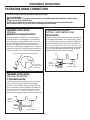
Installation Instructions
FILTRATION DRAIN
CONNECTION (cont.)
SECONDARY INSTALLATION:
237,21'³'5$,1/,1(
ADAPTER INSTALLATION
CAUTION: Using Option D may result
in clogging under adverse conditions and requires
periodic inspection/cleaning by the user.
DO NOT INSTALL THE DRAIN LINE DOWNSTREAM
OF A DISPOSER OR IN A HORIZONTAL PIPE. Install
the drain line adapter under the sink as shown (parts
included). The baffle tee shown must be installed
to prevent a clog in the Reverse Osmosis drain line.
Route the drain line from the air gap to the drain
line adapter, ensure that there are no dips, loops or
low spots in the line. The drain line adapter should
be aligned vertically so that the hose connection
points upward (the hose connection should never
be allowed to drop below 45° from this vertical
position). This installation MAY result in a slight drain
noise in the sink drain when the Reverse Osmosis
system is regenerating. If this happens, simply place
the sink drain stoppers in the strainer to suppress it.
Reverse
Osmosis
drain line
Drain line
adapter
Maximum 45°
Baffle tee
(mandatory)
Optional
disposer
From second
sink or
disposer
From faucet air gap
Drain line
adapter
Drain line connection should
be 180° opposite existing
horizontal pipe/baffle-tee as
shown in diagram
45°
Drain line adapter
Proper drain line adapter orientation.
18
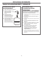
STORAGE TANK AND
STARTUP
STORAGE TANK INSTALLATION
1. Remove the protective cap from the top of the
tank.
2. Apply 2–3 wraps
of thread tape,
in a clockwise
direction, to the
tank threads.
3. Install the push-to-connect fittings on the
threaded fitting on the tank as shown.
4. Push the 3/8” red banded tubing from the
Reverse Osmosis System into the fitting on the
storage tank.
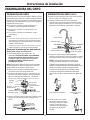
SYSTEM STARTUP PROCEDURE
IMPORTANT ³ If installing the unit in new
construction, ensure that house plumbing is flushed
thoroughly before opening the water supply valve.
1. Check that all tubing connections are secure.
2. Turn on the Feed Water Supply Valve.
3. Check all connection points for leaks.
4. Follow the Sanitization procedures on page 20.
5. After sanitization is complete, reinstall prefilter,
postfilter and Reverse Osmosis cartridges.
6. Membrane contains a food grade preservative.
Allow the system to fill the tank, then drain it
completely four times before using the water
from the system.
7. Recheck all water connection points a few days
later to check for small leaks.
Storage tank
Thread
tape

Prefilter, Postfilter and Reverse Osmosis Membrane Cartridge Replacement Procedure
When the amber filter light in the faucet base flashes, it is
time to replace the prefilter and postfilter. This will occur
every 6 months.
Be sure to wash your hands before handling inner parts of
the system.
1. Turn OFF the icemaker (if attached to the system).
2.
Turn off water supply to the system.
3. Turn ON faucet to drain tank (may take several minutes). Turn
OFF faucet when tank is empty.
4. Remove the prefilter, postfilter and Reverse Osmosis cartridge
by rotating to the left about 1/3 turn.
5. Follow Sanitizing the Reverse Osmosis System procedure found
on page 20.
6. Remove foil on top of new replacement cartridges. Install new
cartridges into the manifold by turning to the right about 1/3
turn until the alignment marks line up and the cartridges stop.
DO NOT OVER TIGHTEN. The cartridges will rise up as they are
turned.
NOTE: The prefilter and postfilter are identical. You may
install either filter in the prefilter or postfilter position. The
reverse osmosis cartridge is installed in the center position.
7. Turn ON water supply to fill the system (may take up to four
hours). Check for leaks.
8. Remove the battery tray and replace the battery, positive “+”
side up, to reset timer and monitor function in faucet base (see
Battery Installation for proper procedure).
NOTE: Allow at least 90 seconds to elapse before installing
new battery. This will ensure a full electronic reset and proper
operation for the next 6 months.
9. If only the prefilter and postfilter are replaced, turn the faucet
ON and fill and empty the storage tank two (2) times. If the
membrane cartridge is replaced, fill and empty the storage
tank a total of four times. (This will remove
the food grade preservatives contained in new membranes.
This preservative will give product water an unpleasant taste
and odor.)
10. Once the storage tank is full, turn on the icemaker.
NOTE: System should be sanitized when replacing the prefilter
and postfilter cartridge or the Reverse Osmosis cartridge. Follow
the Sanitizing the Reverse Osmosis System. procedure on page
20.
ON
OFF
To remove
Reverse
Osmosis
Prefilter
Postfilter
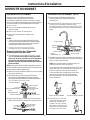
Care and cleaning of the reverse osmosis system.
GEAppliances.com
19

Sanitizing the Reverse Osmosis System
Sanitize upon installation of the Reverse Osmosis system and
after servicing inner parts, including replacement of prefilter,
postfilter and the membrane cartridge.
Be sure to wash your hands before handling inner parts of the
system.
IMPORTANT ³Before sanitizing, be sure
to remove all cartridges. Chlorine will destroy the Reverse Osmosis
membrane cartridge.
1. Follow steps 1 through 4 under Prefilter, Postfilter and Reverse
Osmosis Membrane Cartridge Replacement Procedure.
2. Fill the empty canister labeled “Sanitization Canister” with water
to within 1 inch of the upper opening. Add 1 oz.
(2 Tbsp.) ordinary unscented household bleach. Install canister
into the prefilter canister position by turning to the right about
1/3 turn until the alignment marks line up and the canister
stops.
3. Install the two additional “sanitization canisters” into the
membrane canister and postfilter openings in the manifold by
turning to the right about 1/3 turn until the alignment marks line
up and the canister stops.
4. Turn ON water supply. Turn ON faucet until water begins to
flow from the faucet, then turn faucet OFF. Allow system to
fill for 10 minutes.
5. Turn faucet ON and allow water to flow for 20 minutes, or until
bleach odor is gone. Turn OFF water supply again. Turn ON
faucet to drain the system.
6. Once the system is drained, turn the faucet OFF and remove the
canisters by turning to the left about 1/3 turn. Keep these in a
safe place until needed the next time.
Prefilter
position
Sanitization
canisters
20
Care and cleaning of the reverse osmosis system.
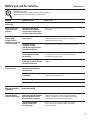
To obtain replacement filters, call toll-free GE Appliance Parts at 800.626.2002 (U.S.),
800.663.6060 (Canada–English), 800.361.3869 (Canada–French), or visit the store where you purchased
your reverse osmosis system.
WARNING: To reduce the risk of physical injury:
Depressurize system as shown in manual prior to cartridge removal.
3UHILOWHU3RVWILOWHU&DUWULGJH5HSODFHPHQW)4523) &DUERQ%ORFN
Reverse Osmosis Cartridge Replacement FQROMF Thin Film Polyamide
The Water Test Kit
To obtain an independent laboratory water test kit, please call Legend Technical Services at 1.800.949.8220 and leave your contact
details. They will contact you to find out what water tests you are interested in, and inform you of the cost of the testing. You will
then receive a kit that will include all necessary tests to properly indicate the performance level of your system. Product water
should be tested a minimum of every six months.
NOTE::KHQWKH7'6UHGXFWLRQRIWKHV\VWHPIDOOVEHORZLWLVWLPHWRUHSODFHWKHUHYHUVHRVPRVLVFDUWULGJHLQDGGLWLRQWRWKH
prefilter and postfilter.
Page is loading ...
Page is loading ...
Page is loading ...
Page is loading ...
Page is loading ...
Page is loading ...
Page is loading ...
Page is loading ...
Page is loading ...
Page is loading ...
Page is loading ...
Page is loading ...
Page is loading ...
Page is loading ...
Page is loading ...
Page is loading ...
Page is loading ...
Page is loading ...
Page is loading ...
Page is loading ...
Page is loading ...
Page is loading ...
Page is loading ...
Page is loading ...
Page is loading ...
Page is loading ...
Page is loading ...
Page is loading ...
Page is loading ...
Page is loading ...
Page is loading ...
Page is loading ...
Page is loading ...
Page is loading ...
Page is loading ...
Page is loading ...
Page is loading ...
Page is loading ...
Page is loading ...
Page is loading ...
Page is loading ...
Page is loading ...
Page is loading ...
Page is loading ...
Page is loading ...
Page is loading ...
Page is loading ...
Page is loading ...
Page is loading ...
Page is loading ...
Page is loading ...
Page is loading ...
Page is loading ...
Page is loading ...
Page is loading ...
Page is loading ...
Page is loading ...
Page is loading ...
Page is loading ...
Page is loading ...
-
 1
1
-
 2
2
-
 3
3
-
 4
4
-
 5
5
-
 6
6
-
 7
7
-
 8
8
-
 9
9
-
 10
10
-
 11
11
-
 12
12
-
 13
13
-
 14
14
-
 15
15
-
 16
16
-
 17
17
-
 18
18
-
 19
19
-
 20
20
-
 21
21
-
 22
22
-
 23
23
-
 24
24
-
 25
25
-
 26
26
-
 27
27
-
 28
28
-
 29
29
-
 30
30
-
 31
31
-
 32
32
-
 33
33
-
 34
34
-
 35
35
-
 36
36
-
 37
37
-
 38
38
-
 39
39
-
 40
40
-
 41
41
-
 42
42
-
 43
43
-
 44
44
-
 45
45
-
 46
46
-
 47
47
-
 48
48
-
 49
49
-
 50
50
-
 51
51
-
 52
52
-
 53
53
-
 54
54
-
 55
55
-
 56
56
-
 57
57
-
 58
58
-
 59
59
-
 60
60
-
 61
61
-
 62
62
-
 63
63
-
 64
64
-
 65
65
-
 66
66
-
 67
67
-
 68
68
-
 69
69
-
 70
70
-
 71
71
-
 72
72
-
 73
73
-
 74
74
-
 75
75
-
 76
76
-
 77
77
-
 78
78
-
 79
79
-
 80
80


GE PNRQ20RBL User manual
- Category
- Sanitary ware
- Type
- User manual
Ask a question and I''ll find the answer in the document
Finding information in a document is now easier with AI
in other languages
- français: GE PNRQ20RBL Manuel utilisateur
- español: GE PNRQ20RBL Manual de usuario
Related papers
Other documents
-
 B&R Industries REVERSE OSMOSIS Owner's manual
-
GE Appliances PXRQ400T Owner's manual
-
Watts Premier RO-Pure User manual
-
Glacier Bay HDGROF4 Operating instructions
-
Whirlpool WHAROS5 Operating instructions
-
Pelican Water THD-PRO-RO-ORB User manual
-
 ECOPURE ECOROM User manual
-
-
EcoWater ERO-375 Owner's manual
-
Whirlpool WHAROS5 Installation guide

