
DBW 2010
DBW 2020
DBW 300
Operating Instructions
Coolant Heaters
North American Headquarters
3333 John Conley Drive
Lapeer, MI 48446
Phone (810) 245-2400
Toll-free (800) HEATER-1
Fax (810) 664-7720
Canadian Operations
Toll-free (800) 667-8900
Website: www.webasto.com
Rev. 11/00 699540 (English)

I
WEBASTO DBW SERIES HEATERS
Introduction
Important Information . . . . . . . . . . . . . . . . . . . . . . . . . . . . . . . . . . . . . . . . . . . . . . . . . . . . . . . . 1
General Safety Regulations and Information . . . . . . . . . . . . . . . . . . . . . . . . . . . . . . . . . . . . . . 3
Meaning of Warnings, Cautions and Notes . . . . . . . . . . . . . . . . . . . . . . . . . . . . . . . . . . . . . . . 3
Description
General Description . . . . . . . . . . . . . . . . . . . . . . . . . . . . . . . . . . . . . . . . . . . . . . . . . . . . . . . . . 5
Coolant Heater DBW 2010 . . . . . . . . . . . . . . . . . . . . . . . . . . . . . . . . . . . . . . . . . . . . . . . . . . . . .5
Coolant Heaters DBW 2020 / 300 . . . . . . . . . . . . . . . . . . . . . . . . . . . . . . . . . . . . . . . . . . . . . . . 6
Operating Instructions
Operating your Webasto DBW Series Heater . . . . . . . . . . . . . . . . . . . . . . . . . . . . . . . . . . . . . . 7
Switching On . . . . . . . . . . . . . . . . . . . . . . . . . . . . . . . . . . . . . . . . . . . . . . . . . . . . . . . . . . . . . . . 8
Switching Off . . . . . . . . . . . . . . . . . . . . . . . . . . . . . . . . . . . . . . . . . . . . . . . . . . . . . . . . . . . . . . . 10
Engine Preheating . . . . . . . . . . . . . . . . . . . . . . . . . . . . . . . . . . . . . . . . . . . . . . . . . . . . . . . . . . . 10
Operation with 7-Day Digital Timer . . . . . . . . . . . . . . . . . . . . . . . . . . . . . . . . . . . . . . . . . . . . . . 11
Setting the Digital Timer (Models 1529 & 1531) . . . . . . . . . . . . . . . . . . . . . . . . . . . . . . . . . . . . 13
7-Day Digital Timer Programming and Operating Instructions (Models 1529 & 1531) . . . . . . 14
Operation with 7-Day Electronic Timer Model CDN-1224 . . . . . . . . . . . . . . . . . . . . . . . . . . . . . 16
Timer Operation Modes (Model CDN-1224) . . . . . . . . . . . . . . . . . . . . . . . . . . . . . . . . . . . . . . . 17
CONTENTS

II
WEBASTO DBW SERIES HEATERS CONTENTS
Dip Switch Programming (Model CDN-1224) . . . . . . . . . . . . . . . . . . . . . . . . . . . . . . . . . . . . . . 18
Timer Operation (Model CDN-1224) . . . . . . . . . . . . . . . . . . . . . . . . . . . . . . . . . . . . . . . . . . . . . 23
Maintenance
Maintenance of the Heater . . . . . . . . . . . . . . . . . . . . . . . . . . . . . . . . . . . . . . . . . . . . . . . . . . . .25
Basic Troubleshooting
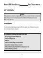
General Information . . . . . . . . . . . . . . . . . . . . . . . . . . . . . . . . . . . . . . . . . . . . . . . . . . . . . . . . . 27
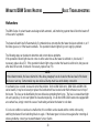
Malfunctions . . . . . . . . . . . . . . . . . . . . . . . . . . . . . . . . . . . . . . . . . . . . . . . . . . . . . . . . . . . . . . . 28
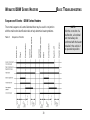
Malfunction Identification - DBW Series Heaters . . . . . . . . . . . . . . . . . . . . . . . . . . . . . . . . . . . 29
Sequence of Events - DBW Series Heaters . . . . . . . . . . . . . . . . . . . . . . . . . . . . . . . . . . . . . . . 30
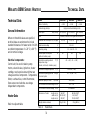
Technical Data
General Information . . . . . . . . . . . . . . . . . . . . . . . . . . . . . . . . . . . . . . . . . . . . . . . . . . . . . . . . . 31
Heater Data . . . . . . . . . . . . . . . . . . . . . . . . . . . . . . . . . . . . . . . . . . . . . . . . . . . . . . . . . . . . . . . . 31
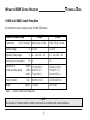
U 4810 and U 4846 Coolant Pump Data . . . . . . . . . . . . . . . . . . . . . . . . . . . . . . . . . . . . . . . . . . 32
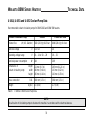
U 4814, U 4851 and U 4852 Coolant Pump Data . . . . . . . . . . . . . . . . . . . . . . . . . . . . . . . . . . . . 33

1
WEBASTO DBW SERIES HEATERS INTRODUCTION
Introduction
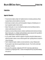
Important Information
• The heater must be installed according to the “Installation Instructions” and must be examined by an officially
recognized, Webasto authorized installation/ servicing facility.
• When the heater is installed in vehicles used for the transportation of dangerous or inflammable goods, or in
boats, the appropriate regulations must be observed.
• Webasto Thermosystems, Inc. does not recommend the installation and servicing of Webasto products by
untrained, unauthorized personnel or end-users.
• Installations and servicing of Webasto products by untrained, unauthorized personnel and end-users will release
Webasto Thermosystems, Inc. and Webasto authorized distributors, dealers and personnel from responsibility for
damage to Webasto product or collateral property and personal injury.
• Any use, operation, installation, modification or application of the product not described in Webasto manuals, or
subjecting the product to extreme or unusual conditions beyond the limits of specified performance characteristics
is misuse of the product.
• Failure to comply with all operation, installation, and servicing instructions is a misuse of Webasto product.
The same applies for repairs without using genuine Webasto service parts. This will void the coolant heaters
“Official Marks of Conformity.”
• In the vicinity of the coolant heater, a temperature of 185 °F (85 °C) must not be exceeded under any
circumstances (e.g. during body paint work). A violation of this temperature limit may cause permanent damage
to the electronics.

2
INTRODUCTIONWEBASTO DBW SERIES HEATERS
WARNING
Due to the danger of poisoning and suffocation, the heater must not be operated in enclosed areas, such as garages
or workshops, without an exhaust venting system, not even if the start-up is activated by the timer or remote start
device.
At filling stations and fuel depots the heater must be switched off as there is a potential danger of explosions.
Where flammable fumes or dust may build up (e.g. in the vicinity of fuel, coal, wood, cereal grain deposits or similar
situations) the heater must be switched off to prevent explosions.
• When checking the coolant level, proceed in accordance with the vehicle manufacturer’s instructions.
• The coolant in the heating circuit of the heater must contain a minimum of 10% of a quality brand glycol based
anti-freeze.
• The pressure setting of the coolant filler cap should be between 0.4 and 2 bar (6 p.s.i. and 28 p.s.i.).
• The coolant heater may only be operated within the specified operating voltage range designated by type.
• The coolant heater may only be operated with the specified fuel (Diesel 1, Diesel 2, Arctic grade, Kerosene and
certain military spec. fuels).
• The operational state of the heater, i.e. an indication “On” or “Off”, must be clearly visible to the operator.
• If electrical welding is to be done on the vehicle, the main positive and negative feed cables should be
disconnected from the battery and securely connected to the chassis. This is necessary to protect the electronic
control unit from voltage surges.

3
WEBASTO DBW SERIES HEATERS INTRODUCTION
General Safety Regulations and Information
The general safety regulations for the prevention of accidents and relevant operating safety instructions must be
observed at all times. The specific safety regulations applicable to this manual are highlighted in the individual
chapters by Warnings, Cautions and Notes.
Meaning of Warnings, Cautions, and Notes
Warnings, Cautions and Notes in this manual have the following meaning:
NOTE:
This heading is used to highlight and draw specific attention to information.
CAUTION
This heading is used to highlight that non-compliance with instructions or procedures may cause damage to
equipment.
WARNING
This heading is used to highlight that non-compliance with instructions or procedures may cause injuries or lethal
accidents to personnel.

4
INTRODUCTIONWEBASTO DBW SERIES HEATERS

WEBASTO DBW SERIES HEATERS DESCRIPTION
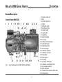
General Description
1 Electronic control unit
2 Motor
3 Electronic ignition coil
4 Coupler
5 Combustion air fan
6 Fuel solenoid valve
7 Electrode holder
8 Coolant outlet
9 Coolant inlet
10 Ignition electrodes
11 Fuel nozzle
12 Overheat fuse (white wires)
13 Control thermostat
14 Temperature limiter
15 Heat exchangers
16 Combustion chamber
17 Combustion air swirler
18 Exhaust pipe
19 Flame detector
20 Fuel pump
21 Fuel supply/ return pipes
22 Combustion air adjusting shutter
23 Fuel pump drive gearing
24 Nozzle pre-heater
25 Preheat thermostat (blue & green wires)
26 Air bleed screw
Fig. 1: Major Components of the DBW 2010 Coolant Heater
5
12345
23
6
25
7
24
81011 12
13
14
9
26
22 21 20 19 18 17 16 15
Coolant Heater DBW 2010

DESCRIPTIONWEBASTO DBW SERIES HEATERS
6
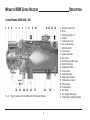
1 Electronic control unit
2 Motor
3 Electronic ignition coil
4 Coupler
5 Combustion air fan
6 Fuel solenoid valve
7 Electrode holder
8 Coolant inlet
9 Ignition electrodes
10 Fuel nozzle
11 Overheat fuse (white wires)
12 Control thermostat
13 Temperature limiter
14 Coolant outlet
15 Heat exchangers
16 Combustion chamber
17 Combustion air swirler
18 Exhaust pipe
19 Flame detector
20 Fuel pump
21 Fuel supply/ return pipes
22 Combustion air adjusting shutter
Fig. 2: Major Components of the DBW 2020 / 300 Coolant Heaters
1 2 3 4 5 6 7 8 10 11 12 13 149
22 21 20 19 18 17 16 15
Coolant Heaters DBW 2020 / 300

OPERATING INSTRUCTIONS
Operating Instructions
Operating your Webasto DBW Series Heater
WARNING
Due to the risk of carbon monoxide poisoning and asphyxiation, the heater must never be operated in closed spaces
such as garages and workshops without adequate exhaust extraction.
WARNING
Due to the risk of fire or explosion, the heater must be switched off while refueling and at fueling stations.
WARNING
Due to the risk of explosion, the heater must never be operated in areas where explosive materials, fumes or dusts
may be present.
7
WEBASTO DBW SERIES HEATERS

WEBASTO DBW SERIES HEATERS
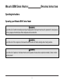
Switching On
Before switching the Webasto heater on, open any shut off valves and set vehicle heater controls to the “Hot”
position. Depending on the type of control installed, the heater can be operated by the following methods.
Timer: Switch:
Using a Timer:
Upon pressing the “Instant Heat” button on the timer face, the “Operation Indicator” on the timer lights up and the
heater begins operation.
Using a Switch:
When the switch is used for switching “ON” the Webasto heater, the “Operation Indicator” integrated in the switch is
illuminated.
8
OPERATING INSTRUCTIONS

OPERATING INSTRUCTIONS
Heater Start-up Sequence:
Upon switching on, an operating indicator light will illuminate.
The combustion air fan, fuel pump and circulation pump start operation. (If fitted and temperature is < 0 °C (< 32 °F)
nozzle preheating is also activated).
After approximately 15 seconds the fuel solenoid valve opens allowing fuel to flow to the nozzle where it is atomized
and sprayed into the combustion chamber. At the same time, a high voltage ignition spark is generated at the
electrode tips simultaneously igniting the fuel air mixture. A photo control device detects a flame in the combustion
chamber and deactivates the ignition system (combustion process is self-sustaining). At this point the heater is
working and producing heat.
The Webasto heater will cycle on and off until:
1. System coolant reaches operating temperature.
2. The Webasto heater is switched off.
3. Time has elapsed on the timer.
4. The vehicle battery voltage drops below 10.5V for 12 volt systems or 20.0V for 24 volt systems.
5. The Webasto heater runs out of fuel.
6. A fault lock out occurs, indicated by the operating indicator light being off during the cool down cycle (as would
happen during an overheat situation.
NOTE:
If the heater is switched on while the engine is at operating temperatures above 140 °F (60 °C) for orange and white
wire thermostat or 155 °F (68 °C) for red and green wire thermostat, only the operation indicator and the coolant
circulation pump will be activated. Depending on the type of thermostat installed, the engine coolant temperature
must fall below 140 °F (60 °C) or 155 °F (68 °C) at the heater before the heater will begin heating operation.
9
WEBASTO DBW SERIES HEATERS

WEBASTO DBW SERIES HEATERS
Switching Off
When heating is no longer required, switch the Webasto heater off. The fuel solenoid valve interrupts the fuel supply
and combustion stops. The indicator light turns off. The Combustion air fan and the water pump continue operation
for approximately 150 seconds (after-run cycle) purging the combustion chamber of any fumes and cooling the
heater.
Engine Preheating
1. Set the timer 10 min. to 120 min. before you want to start the engine. The heater will start up at the set time.
(See timer operating instructions). Or switch the toggle switch or “Instant On” switch on your timer in the vehicle
dash to “On”. The heater will start up.
2. When the run time has elapsed on your timer or engine preheating is no longer required, switch the Webasto
heater “Off”. The heater will begin the after-run (cool-down) cycle.
NOTE:
Switching the Webasto heater on during the cool-down (after-run cycle) period is allowed. The heater will revert to
normal operational mode.
NOTE:
Make sure all coolant and cab heater valves are open before operating the heater in the preheat mode.
10
OPERATING INSTRUCTIONS

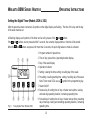
OPERATING INSTRUCTIONS
The digital timer with 3 time settings permits the
Webasto heater to be switched on and off instantly, or
automatically at 3 programmable starting times.
The operating time of the heater can be pre-selected.
It is possible to program 3 different heating times
according to your individual needs.
Only one preset starting time can be activated at any
one time. When the ignition is switched on, the
current time of the day and the day of the week are
displayed.
When the heater is in operation, the display and the
buttons of the timer are illuminated.
11
WEBASTO DBW SERIES HEATERS
Operation with 7-Day Digital Timer (Model 1529 Shown)

WEBASTO DBW SERIES HEATERS
Programmed Heater Operation
Three memory locations numbered 1 to 3 are available. Each memory location can be assigned a given time
together with the day of the week.
Pre-selected Starting Times
The pre-selected starting time is the time at which the heater will be switched on automatically.
We recommend that memory locations 1 and 2 be used for presetting starting times within 24 hours of setting the
timer. Memory location 3 can be used for a starting time within the next 7 days of setting the timer.
NOTE:
We recommend that memory locations 1 and 2 be used for presetting starting times within a 24 hour period of setting
the timer. Memory location 3 can be reserved for a starting time within the next 7 days of setting the timer. Location
3 is useful for occasional weekend or field trip operations outside of the normal schedule. By repeatedly pressing the
button on the 1529 timer or button on the 1531 timer, starting time program 1, 2 or 3 can be viewed and preset.
Operating Time
The period of time during which the heater is in operation is referred to as the operating time. The heater remains in
operation for as long as the operating time has been preset. Heater operation can be pre-selected for any time from
a minimum of 1 minutes (a minimum of 10 minutes is recommended) to a maximum of 120 minutes (factory preset is
60 minutes).
Remaining Operating Time
The remaining operating time refers to the period of time the heater still continues to remain in operation. It can only
be changed while heater is in operation.
12
OPERATING INSTRUCTIONS

OPERATING INSTRUCTIONS
After the power has been connected, all symbols on the digital display are flashing. The time of the day and the day
of the week must be set.
All flashing displays and symbols of the timer can be set by means of the and buttons.
If the and buttons are not pressed within 5 seconds, the currently displayed time or function will be stored.
When the and buttons are pressed for more than 2 seconds, the quick digit advance mode is activated.
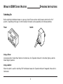
Fig. 3: 7-Day Digital Timer (Model 1529)
13
WEBASTO DBW SERIES HEATERS
1 Program number for preset time.
2 Time of day / preset time / operating duration display.
3 Day of the week display.
4 Operation indicator.
5 Setting / viewing the time; setting / recalling day of the week.
6 Presetting / recalling starting time; setting / recalling day of the week.
Note: Timer model 1531 uses a symbol for the programming key.
7 Heater On/Off.
8 Reverse key for setting time of day or heater start-up time; viewing
and reducing operating duration / remaining operating time.
9 Forward key for setting time of day or heater start-up time; presetting
day of start-up; viewing and extending operating duration / remaining
operating time.
Setting the Digital Timer (Models 1529 & 1531)

WEBASTO DBW SERIES HEATERS
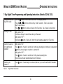
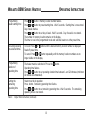
7-Day Digital Timer Programming and Operating Instructions (Models 1529 & 1531)
Setting the time and
day of the week
Viewing the time
Switching heater on
for instant heater
operation
Press the button for more than 2 seconds. Time display flashes.
Press the or button to set time of day. Wait 5 seconds. Time is now stored.
Day of week flashes.
Press or button to set day of week. Wait 5 seconds. Day of week is now stored.
With ignition “ON”:
Continuous display of current time and day of the week.
With ignition “OFF”:
Briefly press button. Display of current time and weekday appears for 5 seconds.
With ignition “ON”:
Press button. Heater is switched on (continuous heating) and continues to operate until
button is pressed again or ignition is switched off.
With ignition “OFF”:
Press button. Heater is switched on for the preset operating time
(the factory-set heater operating duration is 60 minutes).
Switching the
heater off
Press button. Heater begins cool-down (after-run) cycle and is switched off thereafter.
14
OPERATING INSTRUCTIONS
Table 1: Digital Timer Instructions

OPERATING INSTRUCTIONS
Programming
heater-starting time
Recalling/canceling
pre-selected times
Programming
duration of
operating time
Setting the
remaining
operating time
Press or button. Memory location number flashes.
Press or button to preset starting time. Wait 5 seconds. Starting time is now stored.
Day of week flashes.
Press or button to set day of week. Wait 5 seconds. Day of week is now stored.
The number of memory location remains on the display.
The timer is now in the programmed mode and switches heater on at the preset time.
To recall: Press or button until the desired memory location number is displayed.
Read off preset time.
To cancel: Press or button repeatedly until the memory location numbers are no
longer visible on the display.
The heater must be switched off. Press the button.
Operating time flashes.
Press or button to set operating duration time between 1 and 120 minutes (minimum
10 minutes recommended).
Heater must be in operation.
Press button. Remaining operating time flashes.
Press or button to set remaining operating time. Wait 5 seconds. The remaining
operating time is now stored.
Table 1: Digital Timer Instructions (continued)
15
WEBASTO DBW SERIES HEATERS

16
OPERATING INSTRUCTIONSWEBASTO DBW SERIES HEATERS
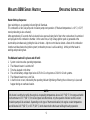
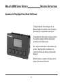
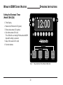
The 7-Day Electronic Timer Model CDN-1224 permits the Webasto heater
to be switched on and off instantly, or automatically.
The timer allows for 1 preset start time once within a 24 hour period on
any one day up to 7 days in advance.
The current time and weekday must be preset before any other
programming features can be accomplished.
The 7-Day Electronic Timer is designed to operate on both 12 and 24 volt
systems.
Operational characteristics of both timer and heater can be tailored to the
requirements of the heating application by pre-programming of the timer.
This is normally done at the time of installation. Four dip switches located on the back panel of the timer are provided
for changing the operational characteristics of the timer. These settings can be revised at any time should your
heating requirements change.
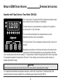
Operation with 7-Day Electronic Timer Model CDN-1224
CAUTION
Timer requires dismounting and disconnecting of power source before revising dip switch settings.
Set Clock
Set Timer
Set
Heater
on/off
manual
Timer
on/off
Display
Hour
Day
Minute
SM
TWT F
S
P
T
H
12:00
For complete timer installation and operation instructions, refer to the 7-Day Electronic Timer Model CDN-1224
Operating Instructions manual available from your Webasto agent under part number 907111.

17
WEBASTO DBW SERIES HEATERS OPERATING INSTRUCTIONS
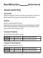
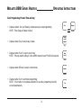
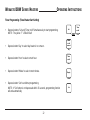
Timer Operation Modes (Model CDN-1224)
Truck or Bus Operation
By flipping one of the dip switches on the back of the unit, the timer can be set for either truck or bus operation. The
tables shown below illustrates the timing sequence associated with operation in either of these modes.
Bus Application
Ignition wire is connected and dip switch #3 is in bus mode.
Whether the heater is turned on manually or automatically, it will stay on until the timer duration ends. Except, when
the heater is turned on manually while the bus is running (ignition key turned on), the heater will shut off when the
ignition key is turned off, or the heater on/off button is pressed.
Truck Application for Preheat Mode Only
Ignition wire is disconnected and dip switch #3 is in truck mode.
Pre-set Mode Heater on Timer duration ends Heater turns off after time duration ends
Manual Mode Heater on Timer duration ends Heater turns off after time duration ends
Truck Application for Preheat and Sleeping Modes
Ignition wire is always live and dip switch #3 is in truck mode.
Pre-set Mode Heater on Timer duration ends Heater turns off after time duration ends
Manual Mode Heater on Timer duration ends Heater stays on until turned off manually
Page is loading ...
Page is loading ...
Page is loading ...
Page is loading ...
Page is loading ...
Page is loading ...
Page is loading ...
Page is loading ...
Page is loading ...
Page is loading ...
Page is loading ...
Page is loading ...
Page is loading ...
Page is loading ...
Page is loading ...
Page is loading ...
Page is loading ...
Page is loading ...
-
 1
1
-
 2
2
-
 3
3
-
 4
4
-
 5
5
-
 6
6
-
 7
7
-
 8
8
-
 9
9
-
 10
10
-
 11
11
-
 12
12
-
 13
13
-
 14
14
-
 15
15
-
 16
16
-
 17
17
-
 18
18
-
 19
19
-
 20
20
-
 21
21
-
 22
22
-
 23
23
-
 24
24
-
 25
25
-
 26
26
-
 27
27
-
 28
28
-
 29
29
-
 30
30
-
 31
31
-
 32
32
-
 33
33
-
 34
34
-
 35
35
-
 36
36
-
 37
37
-
 38
38


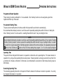
Webastoto DBW 300 Owner's manual
- Category
- Water heaters & boilers
- Type
- Owner's manual
Ask a question and I''ll find the answer in the document
Finding information in a document is now easier with AI
Other documents
-
Webasto AT 2000 STC Operating instructions
-
Webasto AT 2000 S Operating instructions
-
-
-
-
 Sampford IXL CANNON SERIES User Instructions
-
Cannon GMK1011 User and Installation Guide
-
Webasto DBW 2010 Operating instructions
-
-
