Page is loading ...

Emerson Energy Systems
Helios Modular Switch Mode Rectifier
200I/48NT5C05C
Installation and User Manual
V
OL T
A
M P
V O
L
T
C
A
L
C
U R
C
A L
T
H
S
D
H
V
S
D
R
F
A
FA
N
A
L
M
V O
L
T
+ V O
U
T
-
S
E
N
F
A
IL
E
Q L
A C
ON
C L
FF
1
1
.
0
A
F
F
2
1
.0A
C L
A
D
J
E
Q
L
A
D
J
E Q
L
F
LT
A
DJ
H
VS
D
A D
J
I
I
S
T
U
P
D
L
Y
S
L
S
F
S
D C
/
C C
A
C
/
C
A
I
0
H
E
L
I
O
S
F
L
T
P0745680 Standard 6.00 October 2001
UM5C05C ( 169-2081-501 )


3
Emerson Energy Systems Rectifier 200I/48NT5C05C Installation and User Manual
Helios Modular Switch Mode Rectifier
200I/48
NT5C05C
Installation and User Manual
Manual Number : UM5C05C ( 169-2081-501 )
Manual Status : Standard
Manual Issue : 6.00
Release Date : October 2001
P0745680
Copyright 2001 Astec International Ltd
All Rights Reserved
Published in Canada
The information contained in this manual is the property of Astec International Ltd and is subject to change without
notice. Astec International Ltd reserves the right to make changes in design or components as progress in engineering
and manufacturing may warrant. Except as specifically authorized in writing by the V.P. of Engineering and Product
Manufacturing of Astec International Ltd, the holder of this manual shall keep all information contained herein confidential
and shall protect same, in whole or in part, from disclosure and dissemination to all third parties, and use the same for
start-up, operation, and maintenance purposes only. Any modification to the equipment must be approved by the person
responsible for product safety and design quality at Astec International Ltd to insure that the equipment complies with the
operation standards.
This equipment has been tested and found to comply with the limits for a Class A digital device, pursuant to part 15 of the
FCC Rules. These limits are designed to provide reasonable protection against harmful interference when the equipment
is operated in a commercial environment. The equipment generates, uses, and can radiate radio frequency energy, and if
not installed and used in accordance with the instructions contained in the Installation and User Manuals, can cause
harmful interference to radio communications. Operation of this equipment in a residential area is likely to cause harmful
interference, in which case the user will be required to correct the interference at his own expense.
Helios and Helios Candeo are trademarks of Astec International Ltd. The Emerson logo is a trademark and service mark of
Emerson Electric Co.


5
Emerson Energy Systems Rectifier 200I/48NT5C05C Installation and User Manual
Publication history
October 2001
Standard Issue 6.00. Manual restructured and updated to reflect Emerson
Energy Systems and Emerson Network Power identities. ( ECN 102-26804 )
March 1998
Issue 5.0. Standard. Reference change from NT5C05CB to NT5C05C.
July 1997
Issue 4.0. Standard EMI compliance information and table of content
numbering corrections.
June 1995
Issue 3.0. Standard. Revised rectifier installation procedure in a cabinet.
September 1994
Issue 2.0. Standard. Few revisions and additions from the previous issue.
July 1994
Issue 1.0. Standard. Few changes from the previous issue and the document
is now rated “Standard”

6 Publication history
UM5C05C P0745680 Standard 6.00 October 2001 Emerson Energy Systems
This page is left blank intentionally.

7
Emerson Energy Systems Rectifier 200I/48NT5C05C Installation and User Manual
Contents
1. General information .................................................................................... 11
1.1. Purpose of this manual ..............................................................................11
1.2. Models and mounting configurations ......................................................... 12
2. Specifications..............................................................................................13
2.1. Mechanical and electrical specifications.................................................... 13
2.2. Operation specifications and ambient conditions....................................... 14
2.3. Mechanical and electrical specifications of a 1200 A cabinet.................... 16
2.4. Ambient conditions of a 1200 A cabinet..................................................... 16
3. Installation.................................................................................................... 17
3.1. Mounting configurations.............................................................................17
3.2. Tools and test equipment...........................................................................17
3.3. Cautions and Warnings.............................................................................. 17
3.3.1. Installing in a frame.............................................................................. 20
3.3.2. Installing in a cabinet ........................................................................... 20
3.4. Cabling and connecting.............................................................................. 22
3.5. Connecting the dc output terminals to the busbars.................................... 23
3.5.1. Securing the dc output terminals to the busbars in a 1200 A cabinet . 24
3.5.2. Running and connecting the dc between busbars and a rectifier........ 24
3.6. Connecting ac to the rectifiers.................................................................... 24
3.7. Connecting the control signals................................................................... 28
3.7.1. Monitoring of the shunt current............................................................ 29
4. Functional description................................................................................ 31
4.1. Overview .................................................................................................... 31
4.1.1. Input circuit .......................................................................................... 31
4.1.2. Output circuit........................................................................................ 31
4.1.3. Monitoring and control circuits............................................................. 32
4.1.4. Output capacitors................................................................................. 32
4.2. Description of the front panel.....................................................................32
4.2.1. Breakers .............................................................................................. 32
4.2.2. Switches, controls and LEDs............................................................... 33
4.2.3. Front panel LEDs.................................................................................34
4.2.4. Local and remote adjustments and controls........................................ 35
4.2.5. Voltage / current displaytest and measurement...............................36
4.2.6. Float and equalize voltage control....................................................... 37
4.2.7. Current limit adjustment and rectifier regulating test........................... 37
4.2.8. Rectifier parallel operation...................................................................38
4.2.9. HVSD ( high voltage shutdown )..........................................................40
4.2.10. TR ( temporary inhibition ) and sequential start................................... 40
4.2.11. Control signals on connector P1.......................................................... 42
5. Operation...................................................................................................... 45
5.1. Standard settings ....................................................................................... 45
5.2. Starting up and adjusting ........................................................................... 46

8 Contents
UM5C05C P0745680 Standard 6.00 October 2001 Emerson Energy Systems
6. Maintenance................................................................................................. 49
6.1. Replacing the air filter ................................................................................49
6.2. Replacing the fan unit ................................................................................ 49
6.3. Calibrating the Volt / Amp Multimeter......................................................... 50
6.4. Resetting the rectifier after an HVSD ( high voltage shutdown )................ 51
7. Troubleshooting.......................................................................................... 53
8. Appendix A : Replacement parts ............................................................... 55
9. Appendix B : Technical service assistance.............................................. 57
9.1. Local toll-free prefixes................................................................................ 57
9.2. Toll-free technical assistance numbers...................................................... 58
10. Abbreviations and acronyms..................................................................... 59
List of Figures
Figure 1 - Front view of the modular 200I / 48 switch mode rectifier................... 11
Figure 2 - Typical mounting in a cabinet or frame................................................ 12
Figure 3 - Anchoring the cabinet..........................................................................21
Figure 4 - Installing the rectifier............................................................................ 22
Figure 5 - Connecting the dc to the busbars with a shunt on the battery
side or a shunt on the ground side ...................................................... 23
Figure 6 - Cabling ac the NT5C05CA / CB rectifiers............................................ 26
Figure 7 - Connect the power leads to the L1, L2 and L3 terminals of the
rectifier................................................................................................. 26
Figure 8 - Connecting ac to the rectifier NT5C05CC...........................................27
Figure 9 - Typical connections between rectifiers and the conventional
controller.............................................................................................. 28
Figure 10 - Front panel controls and LEDs.......................................................... 33
Figure 11 - Replacing the fan unit........................................................................49
List of Tables
Table 1 - Mechanical specifications of the rectifier.............................................. 13
Table 2 - Electrical specifications of the rectifier.................................................. 13
Table 3 - Operation specifications of the rectifier ................................................ 14
Table 4 - Ambient conditions for the rectifier ....................................................... 15
Table 5 - Mechanical specifications of the NT6C43CB 1200 A cabinet .............. 16
Table 6 - Electrical specifications of the NT6C43CB........................................... 16
Table 7 - Ambient conditions for the NT6C43CB 1200 A cabinet........................16
Table 8 - Pin assignment for connectors J7 to J12.............................................. 29
Table 9 - Pin assignment for connector J13........................................................ 30
Table 10 - Designation of the LEDs on the front panel........................................ 34
Table 11 - Adjusting the potentiometers and switches ........................................ 36
Table 12 - Rectifier input / output signals to the controller...................................36
Table 13 - Setting the start-up delay....................................................................41
Table 14 - Control signal connections on P1....................................................... 42
Table 15 - Standard settings for the rectifier........................................................ 45
Table 16 - Diagnosing system faults.................................................................... 53
List of Procedures
Procedure 1 - Installing the rectifier in a frame.................................................... 20
Procedure 2 - Installing a rectifier in a cabinet.....................................................21
Procedure 3 - Securing the dc output terminals to the busbars of the cabinet.... 24
Procedure 4 - Typical dc cabling in a frame application ......................................24
Procedure 5 - Cabling the ac input to the NT5C05CA / CB rectifiers .................. 25

Contents 9
Emerson Energy Systems Rectifier 200I/48NT5C05C Installation and User Manual
Procedure 6 - Connecting the ac male plug between the NT5C05CC rectifier
and the ac female plug in a 1200 A cabinet.................................. 27
Procedure 7 - Connecting the NT5C05CC to the controller................................. 28
Procedure 8 - Connecting an NT5C05CC rectifier directly to a controller ...........29
Procedure 9 - Starting up the rectifier..................................................................46
Procedure 10 - Replacing the fan unit ................................................................. 50
Procedure 11 - Calibrating the meter................................................................... 51
Procedure 12 - Resetting the rectifier after a high voltage shutdown.................. 51

10 Contents
UM5C05C P0745680 Standard 6.00 October 2001 Emerson Energy Systems
This page is left blank intentionally.

11
Emerson Energy Systems Rectifier 200I/48NT5C05C Installation and User Manual
1. General information
1.1. Purpose of this manual
This manual provides installation, operation and maintenance information
for the NT5C05CA / CB / CC 200I modular switch mode rectifiers with an
input voltage of 380 / 415 V ac and an output capacity of 200 A at a
nominal voltage of –48 volts. This manual covers all applications of the
rectifier referred to as the 200I ( “I” standing for “International” ) market.
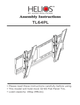
Figure 1 - Front view of the modular 200I / 48 switch mode rectifier
V
O
L T
A M
P
V O L
T
C
A
L
CU
R
CA
L
T
H
S
D
H
V
S
D
R F A
F
A
N
A L
M
V
OL T
+ V
O U
T-
S
E
N
F A
I
L
E
Q L
A C O N
C
L
F
F 1
1
.
0
A
F F2
1
.
0
A
C
L
A
D J
E
Q L
A
D J
E
QL
F
L
T
A D
J
H
V
S D
A
D J
I
I
S
T U
P
D
L Y
S
L
S
F S
D
C
/
C
C
A
C
/
C
A
I
0
H E L I O S
F
LT
The NT5C05CA / CB / CC rectifiers are designed to operate continuously
in a -48 V power system, equipped with or without batteries. It can be
integrated into a small-embedded system or a larger power plant
configuration. It is forced air-cooled by four fans contained in the unit, one
of which is are redundant, if one fan fails this will not cause a shutdown of
the rectifier. The rectifiers can be operated in conjunction with other
Emerson rectifiers as well as with the models and conventional controllers
of other manufacturers available on the market.

12 General information
UM5C05C P0745680 Standard 6.00 October 2001 Emerson Energy Systems
1.2. Models and mounting configurations
Two models of 200I rectifiers are available :
• Models NT5C05CA / CB, without an ac cable
• Model NT5C05CC, equipped with an ac cable terminated with a
male plug
Up to six switch mode 200I rectifiers can be installed in a 23-inch
NT6C43CB 1200 A cabinet or in an NT6C40 type frame. The cabinet is
specifically designed to provide modularity within a very compact unit.
For wooden floor applications in a zone 4 seismic region, up to three
rectifiers can be installed in a mounting frame mounting, but they must
be
installed in the three lowest mounting positions in the frame.
Figure 2 - Typical mounting in a cabinet or frame
RECTIFIER No. 1
RECTIFIER No. 2
RECTIFIER No.3
RECTIFIER No. 4
RECTIFIER No. 5
RECTIFIER No. 6

13
Emerson Energy Systems Rectifier 200I/48NT5C05C Installation and User Manual
2. Specifications
2.1. Mechanical and electrical specifications
Table 1 - Mechanical specifications of the rectifier
Height :
10.0 inches ( 25.4 cm )
Depth :
22.0 inches ( 55.9 cm )
Width :
20.5 inches ( 52.1 cm )
Weight :
92.6 lbs ( 42 kg )
Table 2 - Electrical specifications of the rectifier
Input voltage :
Nominal : 380 / 415 V ac
Range : 330 ±5 V ac to 475 ±5 V ac
Frequency : 47 to 63 Hz
Note: After an out of range line condition shutdown,
the rectifiers will restart automatically at a line
voltage within 350 ±5 V ac to 460 ±5 V ac.
Input current :
Nominal: 18 A RMS ( at 415 V ac )
Worst case: 24 A RMS
Input protection :
25 A ac breaker, 3 Ø
Output floating
voltage :
−46 V dc to —58 V dc
Equalizing voltage :
0 to −4 V dc above the floating voltage
High voltage
shutdown :
−52 V to −60 V dc
Output current :
200 A ( 330 to 475 V ac input )
Output protection :
200 – 250 A dc circuit breaker
Current limit :
50% to 105% of the rated output current

14 Specifications
UM5C05C P0745680 Standard 6.00 October 2001 Emerson Energy Systems
2.2. Operation specifications and ambient conditions
Table 3 - Operation specifications of the rectifier
Output regulation :
At the output terminals, the voltage is within ±0.5% of
the set voltage value for all specified input and output
variations, and within ±1% for any combination of
specified input, output and ambient conditions.
Temperature drift :
Unless otherwise stated, all input and output
parameters such as input voltage range, output current
and voltage, current limit, etc. shall not vary more than
2% over the operating temperature range.
Output noise and
ripple :
• less than 22 dB of random noise on C band at voice
frequency over the entire operating range of the
rectifier, including operation in the current limit mode,
and at low, nominal and high input voltage conditions
( with or without batteries and measured at the point
of regulation )
• less than 20 mV RMS in any 3 kHz band between 10
kHz and 20 MHz ( measurements made with or
without batteries at the output terminals of the
rectifier and with the rectifier in the local sensing
mode )
• less than 250 mV peak to peak switching voltage
spikes ( measured differentially with an a 100 MHz
oscilloscope )
Total harmonic
distortion ( THD ) :
Less than 5%.
Efficiency :
Better than 89% at a nominal input voltage of 350 V ac
and for an output current ( load ) greater than 80 A.
Power factor :
Better than 99% with an output current ( load ) greater
than 80 A.
Heat dissipation :
The maximum heat dissipation is 1420 watts
( 4846 BTU / hr ) for an output current ( load ) of 200 A
at –58 V dc ( when the ac input is 330-475 V )
Electromagnetic
interference ( EMI ) :
The NT5C05CA / CB rectifiers when used in the
rectifier cabinet NT6C43CA / CB ( equipped with the
ac EMI filter kit NT6C18KB, or the NT5C05CC without
external EMI filter ) meet the CISPR requirements for
conducted and radiated EMI as specified in Publication
22 for Class "A" equipment.
Reliability:
The rectifier has an MTBF greater than 120 000 hours
under normal operating conditions, at 77°F ( 25°C ) as
per Telcordia Technologies TR332 method.

Specifications 15
Emerson Energy Systems Rectifier 200I/48NT5C05C Installation and User Manual
Table 4 - Ambient conditions for the rectifier
Operating
conditions
A minimum airflow clearance of 2 inches ( 5 cm ) is
required at the rear of the rectifier.
The rectifier will operate properly under the following
conditions.
Temperature: 32°F to 122°F ( 0°C to +50°C )
32°F to 104°F ( 0°C to +40°C ) with air
filters
Humidity: 0 to 95% RH ( non-condensing ) at 4
kPa max. equiv. to 7,000 ft. ( 2,100 m )
above sea level
Transportation
conditions
During transportation, the rectifier can be subjected to
the following conditions without sustaining damage.
Temperature: –67°F ( –55°C ) for 16 hours
140°F ( +60°C ) dry heat
Humidity: 0 to 95% RH ( non-condensing ) at
4 kPa max.
Vibration: 38 mm / s max. ( 10 Hz to 30 Hz )
sinusoidal, 18-inch ( 457 mm ) drop
when packaged
Pressure: 12 kPa min. equiv. to 49,212 ft.
( 15,000 m above sea level)
Temperature shock : −58°F to 140°F ( −50°C to 60°C )
Storage conditions
During storage, the rectifier may be subjected to the
following conditions without damage :
Temperature: –67°F ( –55°C ) for 16 hours to 140°F
( +60°C ) dry heat
Humidity: 0 to 95% RH ( non-condensing ) at
4 kPa maximum
The rectifier contains aluminum electrolytic capacitors
that have a shelf life of five years or greater at the
maximum rated storage temperature.

16 Specifications
UM5C05C P0745680 Standard 6.00 October 2001 Emerson Energy Systems
2.3. Mechanical and electrical specifications of a 1200 A cabinet
Table 5 - Mechanical specifications of the NT6C43CB 1200 A cabinet
Height :
84.00 inches ( 213.36 cm )
Depth :
23.63 inches ( 60.0 cm )
Width :
23.63 inches ( 60.0 cm )
Table 6 - Electrical specifications of the NT6C43CB 1200 A cabinet
Input voltage :
380 / 415 V ac three phase
Output voltage :
–46 V dc to –58 V dc
Output current :
1200 A
2.4. Ambient conditions of a 1200 A cabinet
Table 7 — Ambient conditions for the NT6C43CB 1200 A cabinet
Operating
conditions
The cabinet is designed for use under the following
ambient conditions.
Temperature: 0°C to 50°C ( 32°F to 122°F )
0° to 40°C ( 32° to 104°F ) with air
filters
Humidity: 0 to 95% RH ( non-condensing )
Altitude: sea level to 7,000 ft ( 2,100 m )
Storage conditions
During transportation and storage, the acceptable
ambient conditions are :
Temperature: –55°C ( –67°F )
+60°C ( 140°F ) dry heat
Humidity: 0 to 95% RH ( non-condensing )

17
Emerson Energy Systems Rectifier 200I/48NT5C05C Installation and User Manual
3. Installation
3.1. Mounting configurations
The NT5C05CA / CB / CC rectifiers are designed for installation in a
1200 A cabinet ( NT6C43CB ) or in a standard frame ( NT6C40 or
equivalent ). In this chapter, a different procedure is provided for each
mounting method. The rectifiers are shipped loose, not mounted in the
frame or cabinet. Upon reception, remove the rectifier from its shipping
carton and inspect it for physical damage. Report any damage to your
immediate supervisor.
3.2. Tools and test equipment
The following tools and test equipment are required :
• screwdriver, flat blade, 3/16 inch ( 5 mm )
• potentiometer screwdriver, Bourns No. 60, or equivalent
• heavy cable strippers or electrician’s knife
• heavy cable cutters ( AWG 4/0 or metric No. 110 )
• nut drivers ( set )
• socket set ( 1/2 inch or 15 mm drive )
• torque limiting wrench ( 1/2 inch. or 15 mm drive )
• crimper, T&B, 15CA54R Violet die
• digital multimeter, Fluke 8000A or equivalent
3.3. Cautions and Warnings
The following precautions must be adhered to at all times
when handling
and installing power equipment.
CAUTION
Protecting the premises
Protect the floors and walls against damage with sheets of
plywood, cardboard, or other suitable material when
handling the equipment.

18 Installation
UM5C05C P0745680 Standard 6.00 October 2001 Emerson Energy Systems
CAUTION
Preventing damage caused by over-tightening
Do not over-tighten nuts and bolts. Over-tightening can
strip the threads or break the bolts. Apply the appropriate
torque values.
CAUTION
Personal safety and protecting the equipment
Use a dolly truck, forklift, or hoist whenever possible
when handling and moving the equipment, as power
equipment is heavy. If a forklift is used, do not remove the
packing material before having moved the equipment to
its final location. If a dolly truck is used, the packing
material can be removed in the reception area. When
handling cabinets with equipment installed in them,
exercise care to ensure they do not tip over, as they can be
top heavy.
CAUTION
Preventing personal injury
When cutting material, wear gloves and goggles. Break all
corners and sharp edges with a flat file.
CAUTION
Optimizing the life of the equipment
Make sure there are no obstructions in front of the
ventilation openings that can restrict the flow of air.

Installation 19
Emerson Energy Systems Rectifier 200I/48NT5C05C Installation and User Manual
WARNING
Generator requirements for Emerson Energy Systems
Power Systems
For information on selecting ac generators that will
effectively maintain peak performance and operating
characteristics, for all Astec APS power systems, go to the
partners’ section of the Emerson Energy Systems web site
at www.EmersonEnergy-NA.com
. To obtain access to the
partners’ section follow the instructions found on the
partner’ page, or dial our nearest local 1−800 technical
support line ( refer to “Appendix C : Technical service
assistance” of this manual for the telephone number ).
DANGER
Grounding
The frame ground leads must be connected before any
other leads. This is to prevent the cabinets and any other
metal structures from carrying dangerous ac or dc voltage
levels.
DANGER
Protecting against electrical shocks
The cabling of the power plant, and all other required
cabling, must be carried out by qualified personnel and in
conformance with local and national electrical codes. AC
input voltages to the rectifiers are at a dangerous level.
Ensure that the circuit breakers are locked in the OFF
position in the ac service panel before working on the
power plant. Dangerous voltages may be present at the
output dc terminals even if the rectifiers are OFF. Use a
voltmeter to verify for the presence of such voltages. Do
not put the circuit breakers to ON until the entire system
has been assembled and you have been instructed to do so.
Verify, and identify with a tag, the proper polarity of the
battery leads before connecting them to the power plant.

20 Installation
UM5C05C P0745680 Standard 6.00 October 2001 Emerson Energy Systems
DANGER
Short circuit hazard
The rectifiers, and the batteries in particular, can deliver
high current if a short to ground occurs. When working
on live equipment, remove all personal jewellery, use
properly insulated tools, and cover any live busbars with
a insulating sheet of canvas to prevent short circuits that
could be caused by falling tools or parts.
3.3.1. Installing in a frame
When shipped, the NT5C05CA / CB / CC switch mode rectifiers are
configured for installation in a standard frame. As the rectifier is heavy,
use a manual forklift to mount the rectifier in a frame. If a forklift is not
available, two persons, exercising care, can lift the rectifier into place and
secure it.
Procedure 1 - Installing the rectifier in a frame
Step Action
1
Note : Install each rectifier beginning with the lowest mounting
position in the frame.
Align the mounting brackets of the rectifier with the mounting holes in
the frame and insert the locating pins into these holes.
2
Lift the rectifier and align the middle holes in the mounting brackets
of the rectifier with the locating pins inserted in the frame. Slide the
rectifier into position onto the locating pins.
3
Secure the rectifier to the frame by inserting and tightening a
mounting screw ( provided ) in the uppermost holes of each
mounting bracket ( one on the left side and one on the right side ).
4
Remove the locating pins and install the other six mounting screws.
Tighten the screws applying a torque of 6.5 ± 0.5 ft-lbs ( 8.5 ±
0.5 N-m ).
end
3.3.2. Installing in a cabinet
The cabinet is 23.56 inches ( 600 mm ) wide and deep, and 84 inches
( 2134 mm ) high. The anchors provided to secure the cabinet in place are
intended for installation on 3000 psi ( 2 kg per sq. mm ) compressive
strength concrete. Anchors for seismic applications are available upon
request. Slotted holes are provided in the base of the cabinet for anchoring.
The primary locations should be used as a first choice ( see Figure 3 ). If a
steel-reinforcing rod is encountered when drilling the holes for the anchors
/