Cybex Owner’s Manual
8
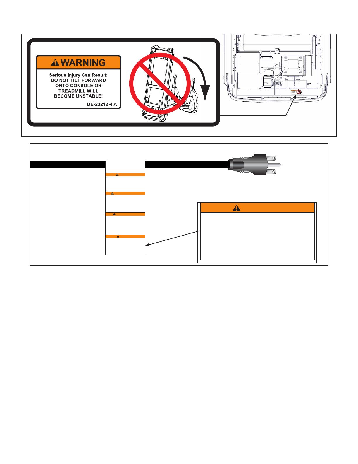
LABEL, WARNING,
DO NOT TILT,
770T
DE-23212-4
B
2
BGarber
2 OF 2
REVISIONS
DESCRIPTION
See sheet 1
ECO
REV
DATE APPROVAL
BY
10 TROTTER DRIVE
MEDWAY, MA
REV.
SHEET
SIZE
APPROVALS
DRAWN BY
MATERIAL
FINISH
ADOBE GENERATED DRAWING
DO NOT MANUALLY UPDATE
CHECKED
RESP ENG
MFG ENG
QUAL ENG
DATE
DWG. NO.
UNLESS OTHERWISE SPECIFIED
DIMENSIONS ARE IN INCHES
TOLERANCES ARE:
.XX ± .02
.XXX ± .010
ANGULAR = ± 1°
FINISH = 125 RMS
FRACTIONS = ± 1/64”
SCALE: 1=1 THIS FILE IS IN ADOBE ILLUSTRATOR
DO NOT SCALE DRAWING
THE INFORMATION CONTAINED IN THIS DRAWING IS THE SOLE PROPERTY OF CYBEX.
ANY REPRODUCTION IN PART OR WHOLE WITHOUT
THE WRITTEN PERMISSION OF CYBEX IS PROHIBITED.
SEE NOTES, Page 1
SEE NOTES, Page 1
.
.
.
12/2/10
Nicht fachgerecht installiertes Netzkabel
kann zu ernsthaften oder tödlichen
Verletzungen führen. Stellen Sie sicher,
dass das Netzkabel wie im Handbuch
angewiesen verlegt wird und weder das
Hebesystem behindert noch von den
Heberädern oder dem
Laufbandrahmen eingeklemmt wird.
WARNUNG
Afin d'éviter tout risque de blessure,
voire de décès, installer correctement
le cordon d'alimentation. S'assurer que
le cordon d'alimentation est acheminé
conformément aux instructions du
manuel et n'interfère pas avec la course
du système d'élévation ni se coince
dans les roues d'élévation ou le cadre
du tapis de course.
AVERTISSEMENT
Si no se instala correctamente el cable
de alimentación, es posible que se
produzcan lesiones graves o la muerte.
Asegúrese de que el cable de alimentación
pase por los lugares correctos tal y como
se indica en el manual y no interfiera con
el desplazamiento completo del sistema
de elevación o sea pellizcado por las
ruedas de elevación o la estructura de la
cinta de correr.
ADVERTENCIA
Failure to correctly install power cord
could result in serious injury or death.
Ensure the power cord is routed as
instructed in the manual and does not
interfere with the full travel of the elevation
system or become pinched by the
elevation wheels or treadmill frame.
WARNING
DE-23098 A
LABEL WARNING,
POWER CORD,
TREADMILL
DE-23098
B
2
BGarber
2 OF 2
REVISIONS
DESCRIPTION
See sheet 1
ECO
REV
DATE APPROVAL
BY
10 TROTTER DRIVE
MEDWAY, MA
REV.
SHEET
SIZE
APPROVALS
DRAWN BY
MATERIAL
FINISH
ADOBE GENERATED DRAWING
DO NOT MANUALLY UPDATE
CHECKED
RESP ENG
MFG ENG
QUAL ENG
DATE
DWG. NO.
UNLESS OTHERWISE SPECIFIED
DIMENSIONS ARE IN INCHES
TOLERANCES ARE:
.XX ± .02
.XXX ± .010
ANGULAR = ± 1°
FINISH = 125 RMS
FRACTIONS = ± 1/64”
SCALE: 1=1 THIS FILE IS IN ADOBE ILLUSTRATOR
DO NOT SCALE DRAWING
THE INFORMATION CONTAINED IN THIS DRAWING IS THE SOLE PROPERTY OF CYBEX.
ANY REPRODUCTION IN PART OR WHOLE WITHOUT
THE WRITTEN PERMISSION OF CYBEX IS PROHIBITED.
SEE NOTES, Page 1
SEE NOTES, Page 1
.
.
.
9/23/10
Nicht fachgerecht installiertes Netzkabel
kann zu ernsthaften oder tödlichen
Verletzungen führen. Stellen Sie sicher,
dass das Netzkabel wie im Handbuch
angewiesen verlegt wird und weder das
Hebesystem behindert noch von den
Heberädern oder dem
Laufbandrahmen eingeklemmt wird.
WARNUNG
Om du inte installerar elkabeln korrekt kan allvarlig
skada eller dödsfall inträffa. Se till att elkabeln är
lagd i enlighet med anvisningarna i bruksanvisningen
och inte stör lyftsystemets hela rörelse eller kan
klämmas fast av lyfthjulen eller löpmaskinens ram.
VARNING
Некорректное подсоединение сетевого
шнура может повлечь причинение
тяжкого вреда здоровью или
смертельный исход. Убедитесь в том,
что сетевой шнур протянут в
соответствии с указаниями в
руководстве пользователя, что он не
препятствует изменению угла наклона
бегового полотна и что он не защемлен
подъемными валиками или рамой тренажера.
ВНИМАНИЕ
Het verkeerd aanbrengen van het stroomsnoer kan
tot ernstig letsel of de dood leiden. Zorg dat het
stroomsnoer geleid is zoals in de gebruiksaanwijzing
is aangegeven en niet in de weg ligt van het volledige
traject van het liftsysteem of geknakt wordt door de
liftwieltjes of het frame van de tredmolen.
WAARSCHUWING
Afin d'éviter tout risque de blessure,
voire de décès, installer correctement
le cordon d'alimentation. S'assurer que
le cordon d'alimentation est acheminé
conformément aux instructions du
manuel et n'interfère pas avec la course
du système d'élévation ni se coince
dans les roues d'élévation ou le cadre
du tapis de course.
AVERTISSEMENT
Si no se instala correctamente el cable
de alimentación, es posible que se
produzcan lesiones graves o la muerte.
Asegúrese de que el cable de alimentación
pase por los lugares correctos tal y como
se indica en el manual y no interfiera con
el desplazamiento completo del sistema
de elevación o sea pellizcado por las
ruedas de elevación o la estructura de la
cinta de correr.
ADVERTENCIA
Failure to correctly install power cord
could result in serious injury or death.
Ensure the power cord is routed as
instructed in the manual and does not
interfere with the full travel of the elevation
system or become pinched by the
elevation wheels or treadmill frame.
WARNING
DE-23098 A
Mangel på korrekt installation af strømkabel kan
medføre alvorlige personskader eller død. Kontroller,
at strømkablet fremføres som angivet i vejledningen,
og at det ikke forstyrrer den fulde bevægelse af
elevationssystemet eller bliver klemt af
elevationshjulene eller løbebåndets ramme.
ADVARSEL
Cord
Wrap
Area


