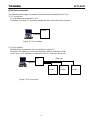
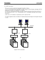
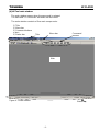
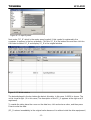
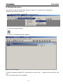
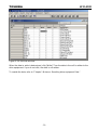
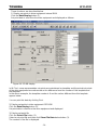
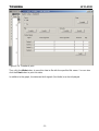
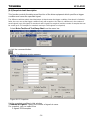
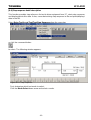
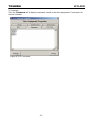
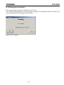
Toshiba 6F3A4508 is a maintenance tool designed to work with Toshiba Wi Series drives. This device offers an array of capabilities, enabling you to perform various tasks related to drive maintenance and operation. Here are a few key features and use cases of the Toshiba 6F3A4508:
Data monitoring and modification: The Toshiba 6F3A4508 allows you to read and write data within the drive equipment, including control values, motor speed, control gain, character string data, and sequence data. This enables you to monitor and adjust drive settings precisely to optimize performance and troubleshoot any issues.
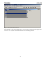
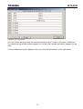
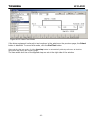
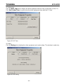
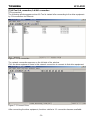


-
 1
1
-
 2
2
-
 3
3
-
 4
4
-
 5
5
-
 6
6
-
 7
7
-
 8
8
-
 9
9
-
 10
10
-
 11
11
-
 12
12
-
 13
13
-
 14
14
-
 15
15
-
 16
16
-
 17
17
-
 18
18
-
 19
19
-
 20
20
-
 21
21
-
 22
22
-
 23
23
-
 24
24
-
 25
25
-
 26
26
-
 27
27
-
 28
28
-
 29
29
-
 30
30
-
 31
31
-
 32
32
-
 33
33
-
 34
34
-
 35
35
-
 36
36
-
 37
37
-
 38
38
-
 39
39
-
 40
40
-
 41
41
-
 42
42
-
 43
43
-
 44
44
-
 45
45
-
 46
46
-
 47
47
-
 48
48
-
 49
49
-
 50
50
-
 51
51
-
 52
52
-
 53
53


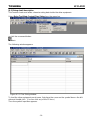
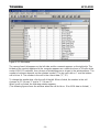
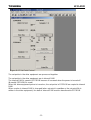
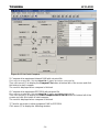
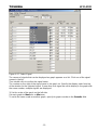
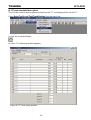
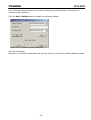
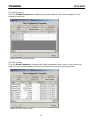
Toshiba 6F3A4508 is a maintenance tool designed to work with Toshiba Wi Series drives. This device offers an array of capabilities, enabling you to perform various tasks related to drive maintenance and operation. Here are a few key features and use cases of the Toshiba 6F3A4508:
Data monitoring and modification: The Toshiba 6F3A4508 allows you to read and write data within the drive equipment, including control values, motor speed, control gain, character string data, and sequence data. This enables you to monitor and adjust drive settings precisely to optimize performance and troubleshoot any issues.
Ask a question and I''ll find the answer in the document
Finding information in a document is now easier with AI
Related papers
-
Toshiba ASD-G9ETH User manual
-
Toshiba S300L (PSSD1C-01L018) User guide
-
Toshiba A600 (PPA61C-02J01S) User guide
-
Toshiba M10 (PTMB3A-05E004) User manual
-
Vizio A10 (PTSB0C-00Q00S) User manual
-
-
Toshiba L500 (PSLS0A-08P002) User manual
-
-
Toshiba Satellite Pro L550D Owner's manual
-
Toshiba R10 (PTRB3C-00D09C) User manual