Page is loading ...

INSTALLATION INSTRUCTIONS FOR PART 99-8212
Socket Wrench • Small Flat Blade Screwdriver • Phillips Screwdriver
1-800-221-0932 www.metraonline.com
KIT FEATURES
© COPYRIGHT 2004-2007 METRA ELECTRONICS CORPORATION Rev.10-02-07
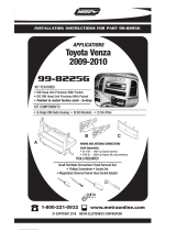
• DIN Head Unit Provisions with Pocket
• ISO DIN Head Unit Pro
visions with Poc
ket
A) Radio Housing w/ Pocket • B) ISO Brackets
C) Radio Housing Brackets • D) (2) PTH-838 Phillips Screws • E) (8) PFH-614 Phillips Screws
F) Trim Plate • G) X-9002 Radio Support Bracket
KIT COMPONENTS
TOOLS REQUIRED:
99-8212
A
APPLICATIONS
2004-2008 Toyota Solara
B
C
D
E
F
G

99-8212
Dash Disassembly . . . . . . . . . . . . . . . . . . . . . . . . . . . . . . . . . 1
Kit Assembly . . . . . . . . . . . . . . . . . . . . . . . . . . . . . . . . . . . . . . 2-4
Final Assembly . . . . . . . . . . . . . . . . . . . . . . . . . . . . . . . . . . . . 5
TABLE OF CONTENTS

99-8212
1
Disconnect the negative battery
terminal to prevent an accidental
short circuit.
1
Remove the cover from the hazard
switch then unclip and remove the
switch.
(Figure A)
2
2004-2008 TOYOTA SOLARA
Unclip and remove panel above radio
including A/C vents and clock.
TIP: Start pulling from the inside of
the hazard switch cavity.
(Figure B)
3
Unclip and remove panel surrounding
shifter.
(Figure C)
4
Unclip and remove pocket and seat
heater switch panel.
(Figure D)
5
DASH DISASSEMBLY
A
B
C
Remove (4) 10mm screws to extract
radio from sub dash.
(Figure E)
6
D
E

99-8212
2
KIT ASSEMBLY
2004-2008 TOYOTA SOLARA
Attach the corresponding radio
housing bracket to the radio housing
using the included (8) PFH-614 Phillips
screws.
1
Slide the factory climate control into the
assembled radio housing brackets/radio
housing assembly and secure with the
factory hardware.
2
Attach the radio support to the back of
the pocket using the supplied (2) PTF-
838 Phillips screws.
3

99-8212
3
KIT ASSEMBLY
Slide the DIN cage into the radio
housing and secure by bending the
metal locking tabs down.
(Figure A)
1
A
Slide the aftermarket head unit into
the cage and secure.
(Figure B)
2
DIN HEAD UNIT PROVISIONS
B

99-8212
4
KIT ASSEMBLY
Mount the ISO Brackets to the head
unit with the screws supplied with
the unit.
(Figure A)
1
A
Slide the head unit into the radio
opening until the side clips engage.
(Figure B)
2
ISO DIN HEAD UNIT PROVISIONS
B
Snap the trim plate into the radio
housing.
(Figure B)
3

99-8212
5
FINAL ASSEMBLY
1
Locate the factory wiring harness in the
dash. Metra recommends using the proper
mating adapter and making the connections
as shown. (Isolate and individually tape off
the ends of any unused wires to prevent
electrical short circuit)
2
Re-connect the negative battery terminal
and test the unit for proper operation.
3
Reassemble radio and dash assemblies in
reverse order of disassembly.
A
A) Strip wire ends back 1/2"
B) Twist ends together
C) Solder
D) Tape
B
C
D

INST99-8212
1-800-221-0932 www.metraonline.com
Rev. 07-02-07 © COPYRIGHT 2004-2007 METRA ELECTRONICS CORPORATION INST99-8212
/