Page is loading ...

TorqueMaster
®
Plus
Installation Instructions and Owner’s Manual
Copyright 2008 Wayne-Dalton Corp. Part No. 327882 Rev 2 3-28-2008
9300 Series
IMPORTANT NOTICE!
Read these instructions carefully before
attempting installation. If in question about
any of the procedures, do not perform the
work. Instead, have a trained door systems
technician do the installation or repairs.

2
Please Do Not Return This Product To The Store. Contact your local Wayne-Dalton dealer. To find your local Wayne-Dalton dealer, refer to your
local yellow pages/business listings or go to the Find a Dealer section online at www.wayne-dalton.com
Definition of key words used in this manual:
INDICATES A POTENTIALLY HAZARDOUS
SITUATION WHICH, IF NOT AVOIDED, COULD
RESULT IN SEVERE OR FATAL INJURY.
CAUTION: PROPERTY DAMAGE OR INJURY CAN RESULT
FROM FAILURE TO FOLLOW INSTRUCTIONS.
IMPORTANT: REQUIRED STEP FOR SAFE AND PROPER
DOOR OPERATION.
NOTE: Information assuring proper installation of the door.
Table of Contents
Important Safety Instructions .................................................. 2
Package Contents ................................................................... 3
Door Section Identification ...................................................... 4
Tools Required ........................................................................ 5
Pre-Installation ....................................................................3-6
Removing An Existing Door ..................................... 5
Preparing The Opening ........................................... 6
Installation ........................................................................7-22
Torquemaster Plus Reset Instructions...............................23-25
Optional Installations .......................................................25-26
Side Lock ............................................................. 25
Pull Rope .............................................................. 26
Trolley Operator .................................................... 26
Maintenance ......................................................................... 26
Cleaning ............................................................... 26
Warranty ............................................................................... 27
Customer Service Number .................................................... 28
WARNING
WARNING
TO AVOID POSSIBLE INJURY, READ THESE INSTRUCTIONS
CAREFULLY BEFORE ATTEMPTING INSTALLATION. IF IN
QUESTION ABOUT ANY OF THE PROCEDURES, DO NOT
PERFORM THE WORK. INSTEAD, HAVE A TRAINED DOOR
SYSTEMS TECHNICIAN DO THE INSTALLATION OR REPAIRS.
1. READ AND FOLLOW ALL INSTALLATION INSTRUCTIONS.
2. Wear protective gloves during installation to avoid possible
cuts from sharp metal edges.
3. It is always recommended to wear eye protection when using
tools, otherwise eye injury could result.
4. Avoid installing your new door on windy days. Door could
fall during the installation causing severe or fatal injury.
5. Doors 12’- 0” wide and wider should be installed by two
persons, to avoid possible injury.
6. Operate door ONLY when it is properly adjusted and free from
obstructions.
7. If a door becomes hard to operate, inoperative or is damaged,
immediately have necessary adjustments and/or repairs
made by a trained door system technician using proper tools
and instructions.
8. DO NOT stand or walk under a moving door, or permit
anybody to stand or walk under an electrically operated door.
9. DO NOT place fingers or hands into open section joints when
closing a door. Use lift handles/gripping points when operating
door manually.
10. DO NOT permit children to operate garage door or door
controls. Severe or fatal injury could result, should the child
become entrapped between the door and the floor.
11. Due to constant extreme spring tension, DO NOT attempt any
adjustment, repair or alteration to any part of the door,
especially to springs, spring brackets, bottom corner brackets,
red colored fasteners, cables or supports. To avoid possible
severe or fatal injury, have any such work performed
by a trained door systems technician using proper tools and
instructions.
12. On electrically operated doors, pull down ropes must be
removed and locks must be removed or made inoperative in
the open (unlocked) position.
13. Top section of door may need to be reinforced when attaching
an electric opener. Check door and/or opener manufacturer’s
instructions.
14. VISUALLY inspect door and hardware monthly for worn and or
broken parts. Check to ensure door operates freely.
15. Test electric opener’s safety features monthly, following
opener manufacturer’s instructions.
16. NEVER hang tools, bicycles, hoses, clothing or anything else
from horizontal tracks. Track systems are not intended or
designed to support extra weight.
17. Avoid installing your door in close proximity to any heat source that
may exceed 200° F. Failure to due so, may cause door sections to
blister and/or warp.
After installation is complete, fasten this manual near garage door.

3
Please Do Not Return This Product To The Store. Contact your local Wayne-Dalton dealer. To find your local Wayne-Dalton dealer, refer to your
local yellow pages/business listings or go to the Find a Dealer section online at www.wayne-dalton.com
Package Contents
NOTE: DEPENDING ON THE DOOR MODEL, SOME PARTS LISTED WILL NOT BE SUPPLIED IF NOT
REQUIRED. REAR SUPPORTS MAY NOT BE INCLUDED WITH YOUR DOOR.
PRE-INSTALLATION
(1) TORQUEMASTER
®
SPRING TUBE ASSEMBLY
1/4” - 14 X 5/8”
SELF TAPPING SCREWS
(AS REQUIRED)
1/4”-20 X 11/16” SELF DRILLING
SCREWS (AS REQUIRED)
(2) 5/16” -18 X 3/4”
CARRIAGE BOLTS
(2) VERTICAL
TRACKS RH/LH
(2) 3/8” - 16 X 3/4”
TRUSS HEAD BOLTS
(1) CENTER BRACKET
ASSEMBLY
(2) QUICK INSTALL
RH/LH FLAGANGLES (AS
REQUIRED)
(2) HORIZONTAL TRACKS RH/LH
ROLLERS
(AS REQUIRED)
(2) HORIZONTAL ANGLES
(AS REQUIRED)
SCREW EYES AND
PULL ROPE
(IF INCLUDED)
5/16” X 1-5/8” HEX HEAD LAG
SCREWS (AS REQUIRED)
WEATHER SEAL & NAILS
(IF INCLUDED)
Q.I. JAMB BRACKETS
(AS REQUIRED)
(2) 3/8”- 16
HEX NUTS
Cable Dr
um
No spa
ce
bet
w
e
e
n
Ratchet
Pawl and Cable Drum
indicates engageme
n
t
C
able D
rum
Ratchet Pawl
ENGAGE
D SIDE VIEW
No space between
Ratchet Pawl and
Ca
ble Drum
ENGAGED
U
NDE
RN
E
A
T
H
V
IE
W
Space between
Rat
c
h
e
t Paw
l
and C
able Dru
m
non-indica
tes engageme
nt
Cable Drum
Ratchet Pawl
DISENGAGED
SIDE VIEW
No
space
between
Ratchet Pawl and
DISENGAGED
U
ND
E
R
NE
A
TH
V
I
E
W
UPPER P
O
S
I
TION
LOWER
POSITION
L
OWE
R POSITION S
IDE VIE
W
UPPER PO
SITION SIDE VIE
W
Ratchet Pawl i
n Lower Position
Ratchet Pawl in Upper Position
Us
e these Illustration
,
in conjunction with the Instructions on the other side of
this lab
el
.
W
ARNING
Rachet Bracket is under
EXTREME SPRING
TENSIO
N
.
To
avoid possible severe or
fatal injury
,
DO NO
T
remove
fasteners from ratchet bracke
t
until spring(s) are full
y
wnwound.
To
safely unwind spring(s)
read
and follow the directions in the
installation instruc
tions/owners
manual
.
DO NOT REMO
VE THIS
TA
G.
Ratchet Pawl
ENG
AG
ED
SI
DE VIEW
No space between
NDER
NEA
T
H
V
I
EW
WARNING
Rachet Bracket is
under
EXTREME SPRING
TENSIO
N
.
To avoid possible severe or
fatal injury
,
DO NO
T
remove
fasteners from ratchet bracket
until spring(s) are full
y
wnwound.
To safely unwind spring(s)
read
and follow the directions in the
installation instructions/owners
manual
.
DO NOT REMOVE THIS
TA
G.
END BRACKETS
LH/RH
(2) TOP BRACKET
SLIDES
(1) LOOSE WINDING SHAFT
(SINGLE SPRING ONLY)
DOOR SECTIONS (AS REQUIRED)
STUD PLATES
(AS REQUIRED)
1/4” - 20
FLANGE HEX NUTS
(AS REQUIRED)
1/4”-20 X 9/16” TRACK
BOLTS (AS REQUIRED)
(2) FULLY ADJUSTABLE
RH/LH FLAGANGLES
(AS REQUIRED)
LH & RH DRUM
ASSEMBLIES WITH
DRUM WRAPS
(4) 1/4” -20 X 1”
CARRIAGE BOLTS
(2) 5/16”- 18
HEX NUTS
(4) 1/4” -20
NYLOCK HEX NUTS

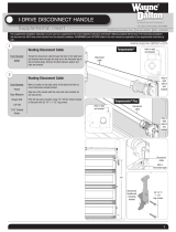
All hinges are factory attached at the top of each
section (except the top section). See illustrations
to the right.
NOTE: The side view illustration shows the roller
carrier profile at the top of each section, and
can be used in conjunction with identifying each
section.
The BOTTOM SECTION can be identified by the
bottom astragal and bottom bracket warning
labels.
The LOCK SECTION can be identified by the lock
stile /or side view.
The INTERMEDIATE I SECTION can be identified
by the warning label on either the right or left
hand side of the section /or side view.
The INTERMEDIATE II SECTION can be identified
by the side view (Used ONLY with 5 section
doors).
The TOP SECTION can be identified by no pre-
installed end or center hinges, and a factory
attached operator stile.
Door Section Identification
TOP SECTION
INTERMEDIATE I SECTION
LOCK SECTION
BOTTOM SECTION
ASTRAGAL
BOTTOM BRACKET
WARNING LABELS
WARNING LABEL
OPERATOR STILE
INTERMEDIATE II SECTION (8”-5 SECTION DOOR ONLY)
LOCK STILE
SIDE VIEW
SIDE VIEW
SIDE VIEW
1 7/8”
2”
1 7/8”
4
Please Do Not Return This Product To The Store. Contact your local Wayne-Dalton dealer. To find your local Wayne-Dalton dealer, refer to your
local yellow pages/business listings or go to the Find a Dealer section online at www.wayne-dalton.com
SIDE VIEW

5
Please Do Not Return This Product To The Store. Contact your local Wayne-Dalton dealer. To find your local Wayne-Dalton dealer, refer to your
local yellow pages/business listings or go to the Find a Dealer section online at www.wayne-dalton.com
IMPORTANT: COUNTERBALANCE SPRING TENSION MUST ALWAYS BE RELEASED BEFORE ANY ATTEMPT IS MADE TO START REMOVING
AN EXISTING DOOR.
A POWERFUL SPRING RELEASING ITS ENERGY SUDDENLY CAN CAUSE SEVERE OR FATAL INJURY. TO AVOID INJURY
HAVE A TRAINED DOOR SYSTEMS TECHNICIAN, USING PROPER TOOLS AND INSTRUCTIONS, RELEASE THE SPRING
TENSION.
For detailed information see supplemental instructions “Removing an Existing Door /Preparing the Opening”. These instructions are available
at no charge from Wayne-Dalton Corp., P.O. Box 67, Mt. Hope, OH 44660, or at www.wayne-dalton.com.
WARNING
Tools Required
POWER DRILL RATCHET WRENCH PLIERS/WIRE CUTTERS
PHILLIPS HEAD SCREWDRIVER PENCIL
1/8”, 3/16” DRILL BITS
FLAT TIP SCREWDRIVER
7/16” SOCKET DRIVER
TAPE MEASURE
NEEDLE NOSE PLIERS
STEP LADDER
7/16”, 1/2”, 9/16”
SOCKETS
3/8”, 7/16”, 1/2”, 9/16”
WRENCHES
SAFETY GLASSES
VICE GRIPSHAMMER SAW HORSES (PAIR)
GLOVES
PRE-INSTALLATION
VICE CLAMPS
Removing An Existing Door

Tools Needed:
6
Please Do Not Return This Product To The Store. Contact your local Wayne-Dalton dealer. To find your local Wayne-Dalton dealer, refer to your
local yellow pages/business listings or go to the Find a Dealer section online at www.wayne-dalton.com
Preparing the Opening
Recommended
tools from
page 5
HEADROOM REQUIREMENT
TRACK TYPE TorqueMaster
®
12” 11”
15” 13-1/2”
DOOR
HEIGHT
TRACK
MANUAL
LIFT
MOTOR
OPERATED
6’5”-7’0” 12”, 15” Radius 98” 125”
8’0” 12”, 15” Radius 110” 137”
BACKROOM REQUIREMENT
Headroom
Backroom
Door
width
Door height
Level header
Plumb jambs
Header board 2” x
6” lumber preferred
Suitable mounting surface
2” x 6” lumber minimum
Header
Jamb
Jamb
FAILURE TO SECURELY ATTACH A SUITABLE
MOUNTING PAD TO STRUCTURALLY SOUND FRAMING
COULD CAUSE SPRINGS TO VIOLENTLY PULL
MOUNTING PAD FROM WALL, RESULTING IN SEVERE
OR FATAL INJURY.
If you just removed your existing door or you are installing a new door, complete
all steps in PREPARING THE OPENING.
To ensure secure mounting of track brackets, side and center brackets, or
steel angles to new or retro-fit construction, it is recommended to follow the
procedures outlined in DASMA Technical Data Sheets #156, #161 and #164 at
www.dasma.com.
The inside perimeter of your garage door opening should be framed with wood
jamb and header material. The jambs and header must be securely fastened to
sound framing members. It is recommended that 2” x 6” lumber be used. The
jambs must be plumb and the header level. The jambs should extend a minimum
of 12” (305 mm) above the top of the opening for TorqueMaster
®
counterbalance
systems. For low headroom applications, the jambs should extend to the ceiling
height. Minimum side clearance required, from the opening to the wall, is 3-1/2”
(89 mm).
IMPORTANT: CLOSELY INSPECT JAMBS, HEADER AND
MOUNTING SURFACE. ANY WOOD FOUND NOT TO BE SOUND,
MUST BE REPLACED.
For TorqueMaster
®
counterbalance systems, a suitable mounting surface (2”
x 6”) must be firmly attached to the wall, above the header at the center of the
opening.
NOTE: Drill 3/16” pilot holes in the mounting surface to avoid splitting the lumber.
Do not attach the mounting surface with nails.
Weather Seal (May Not Be Included):
Cut the weather seal (if necessary) to fit the header and jambs.
NOTE: If nailing product at 40°F or below, pre-drilling is required.
Align the header seal with the inside edge of the header and temporarily secure
it to the header with equally spaced nails. Next, fit the jamb seals up tight against
the header seal and flush with the inside edge of the jamb. Temporarily secure
the jamb seals with equally spaced nails. This will keep the bottom section from
falling out of the opening during installation. Space nails approximately 12” apart.
NOTE: Do not permanently attach weather seal to the jamb at this time.
HEADROOM REQUIREMENT: Headroom is defined as the space needed above
the top of the door for tracks, springs, etc. to allow the door to open properly. If the
door is to be motor operated, 2-1/2” (64 mm) of additional headroom is required.
BACKROOM REQUIREMENT: Backroom is defined as the distance needed from
the opening back into the garage to allow the door to open fully.
Weather Seal
QUICK INSTALL
TRACK
JAMB
WEATHER
SEAL
WARNING

7
Tools Needed:
Please Do Not Return This Product To The Store. Contact your local Wayne-Dalton dealer. To find your local Wayne-Dalton dealer, refer to your
local yellow pages/business listings or go to the Find a Dealer section online at www.wayne-dalton.com
Begin the installation of the door by checking the opening. It must be the same size as the door. Vertical jambs must be plumb and header must be level. Side clearance,
from edge of door to wall, must be a minimum of 3-1/2” (89mm) on each side.
IMPORTANT: STAINLESS STEEL OR PT 2000 COATED LAG SCREWS (NOT SUPPLIED) MUST BE USED WHEN INSTALLING CENTER
BEARING BRACKETS, END BRACKETS, JAMB BRACKETS, OPERATOR MOUNTING/SUPPORT BRACKETS AND DISCONNECT BRACKETS
ON TREATED LUMBER (PRESERVATIVE-TREATED). STAINLESS STEEL OR PT 2000 COATED LAG SCREWS ARE NOT NECESSARY WHEN
INSTALLING PRODUCTS ON UNTREATED LUMBER.
IMPORTANT: WHEN INSTALLING 5/16” DIAMETER LAG SCREWS USING AN ELECTRIC DRILL/DRIVER, THE DRILL/DRIVER’S CLUTCH MUST
BE SET TO DELIVER NO MORE THAN 200 IN. LBS. OF TORQUE. FASTENER FAILURE COULD OCCUR AT A HIGHER SETTING.
NOTE: It is recommended that 5/16” lag screws be pilot drilled using a 3/16” drill bit, prior to fastening.
Installation
INSTALLATION
None
Attaching Quick Install Flag
Angle to Vertical Track
NOTE: If you have fully adjustable flagangles, skip
this step and complete Step 2.
Place the lower quick install tab of the flagangle in
the quick install feature of the vertical track. Give
the flagangle 1/4 turn to lock in place. Repeat for
other side.
NOTE: After completing this step, continue with
Step 3.
QUICK INSTALL TAB UNLOCKED
QUICK INSTALL TAB LOCKED
FLAGANGLE
VERTICAL
TRACK
1
LEFT HAND TRACK AND FLAGANGLE
RIGHT HAND TRACK AND FLAGANGLE
FLAGANGLE
VERTICAL
TRACK

Tools Needed:
8
Tools Needed:
Please Do Not Return This Product To The Store. Contact your local Wayne-Dalton dealer. To find your local Wayne-Dalton dealer, refer to your
local yellow pages/business listings or go to the Find a Dealer section online at www.wayne-dalton.com
Horizontal Angle
Hammer
Attaching Fully Adjustable Flagangle
to Vertical Track
NOTE: If quick install flagangles were installed in
Step 1, skip this step and continue with Step 3.
Hand tighten the flagangle to the vertical track
using (1) stud plate and (2) 1/4” - 20 flange hex
nuts. Repeat for other side.
Secure the flange nuts after flagangle spacing is
complete (Step 10).
None
2
3
Position the horizontal angle as shown.
Place tabs of horizontal angle in the key slot of
horizontal track. Using a hammer, tap the horizontal
angle towards the curved end of the track until the
holes in track and angle are aligned. Repeat for
opposite side. Set tracks aside.
NOTE: For larger doors, a full length horizontal angle
may be spot welded to the horizontal track. If the
horizontal angle is not welded, the horizontal angle
must be installed as shown.
(2) 1/4”- 20 Flange
hex nuts
Fully adjustable
flagangle
Vertical track
Stud plate
Horizontal angle
Hole
Tabs
Key hole slot
Horizontal track
Hole
Horizontal angle
Horizontal track
Horizontal angle
Horizontal track
Tabs

Tools Needed:
9
Please Do Not Return This Product To The Store. Contact your local Wayne-Dalton dealer. To find your local Wayne-Dalton dealer, refer to your
local yellow pages/business listings or go to the Find a Dealer section online at www.wayne-dalton.com
INSTALLATION
Tape Measure
4
Installing Q.I. Jamb Brackets
TWISTLOCK TAB
LEFT SIDE SHOWN
RIGHT SIDE SHOWN
Measure the length of the vertical tracks. Using
the jamb bracket schedule, determine the
placement of the jamb brackets for your door
height and track type.
To install the jamb brackets, align the twistlock tab
on the quick install jamb bracket with the quick
install feature in the track and turn the bracket
perpendicular to the track so the mounting flange
is toward the back (flat) leg of the track.
TOP
HOLE
BOTTOM
HOLE
MIDDLE
HOLE
3RD SET
HOLES
2ND SET
HOLES
1ST SET
HOLES
QUICK INSTALL FEATURE
JAMB BRACKET SCHEDULE
DOOR
HEIGHT
TRACK
LENGTH
1ST SET 2ND SET 3RD SET
JAMB BKT POSITION JAMB BKT POSITION JAMB BKT POSITION
6’5”
69”
(1753 mm)
QIJB - 3 BOTTOM QIJB - 6 MIDDLE NOT APPLICABLE
7’0”
76”
(1930 mm)
QIJB - 3 BOTTOM QIJB - 7 TOP NOT APPLICABLE
8’0”
4 SECTIONS
88”
( 2235 mm)
QIJB - 3 MIDDLE QIJB - 7 TOP QIJB - 8 MIDDLE
8’0”
5 SECTIONS
88”
(2235 mm)
QIJB - 3 BOTTOM QIJB - 7 TOP QIJB - 8 TOP
VERTICAL TRACK

Tools Needed:
10
Please Do Not Return This Product To The Store. Contact your local Wayne-Dalton dealer. To find your local Wayne-Dalton dealer, refer to your
local yellow pages/business listings or go to the Find a Dealer section online at www.wayne-dalton.com
Drums
IMPORTANT: RIGHT AND LEFT HAND
IS ALWAYS DETERMINED FROM INSIDE
THE BUILDING LOOKING OUT.
NOTE: For door section identification see page 4.
TorqueMaster
®
drums are marked right and left
hand. Uncoil the counterbalance cables and make
sure you place the right hand cable loop on the
right hand milford pin and place the left hand
cable loop on the left hand milford pin. Check to
ensure the cable loop fits tightly over the milford
pin.
Failure to ensure tight fit of cable
loop over milford pin could result
in cable coming off the pin and
allowing door to fall, possibly
resulting in severe or fatal injury.
Bottom section: Insert roller into bottom roller
carrier hole and insert another roller into the inner
roller carrier hole, located at the top of the bottom
section.
Lock section: Insert roller into the inner roller
carrier hole.
Intermediate section I: Insert roller into the
outer roller carrier hole.
Intermediate section II (5 section- 8’ Height
only): Insert roller into the Outer roller carrier hole.
None
5
BOTTOM
SECTION
ASTRAGAL
MILFORD
PIN
Bottom Section
Bottom roller
carrier hole
Rollers
Milford pin
Inner roller
carrier hole
Outer roller
carrier hole
Inner roller
carrier hole
Lock and Intermediate Sections
Left hand
counterbalance drum
Top roller
carrier
WARNING

11
Tools Needed:
Tools Needed:
Please Do Not Return This Product To The Store. Contact your local Wayne-Dalton dealer. To find your local Wayne-Dalton dealer, refer to your
local yellow pages/business listings or go to the Find a Dealer section online at www.wayne-dalton.com
Bottom Section
Center the bottom section in the door opening.
Level section using wooden shims (if necessary)
under the bottom section.
Level
Wooden shims
(If necessary)
6
7
Vertical Track
IMPORTANT: THE TOPS OF THE
VERTICAL TRACKS MUST BE LEVEL
FROM SIDE TO SIDE. IF THE BOTTOM
SECTION WAS SHIMMED TO LEVEL IT.
THE VERTICAL TRACK ON THE SHIMMED
SIDE, MUST BE RAISED THE HEIGHT OF
THE SHIM.
Position the left hand vertical track assembly
over the rollers of the bottom section. Make sure
the counterbalance cable is located between the
rollers and the door jamb. Drill 3/16” pilot holes for
the lag screws.
Loosely fasten jamb brackets and flagangle to the
jamb using 5/16” x 1-5/8” lag screws. Tighten
lag screw securing bottom jamb bracket to jamb,
maintaining 3/8”- 5/8” track spacing.
NOTE: Hang cable drum over flagangle.
Repeat for the right hand side.
3/16” Drill Bit
Power Drill
7/16” Socket Driver
Tape Measure
Level
Step Ladder
BOTTOM
SECTION
DOOR OPENING
WITH WEATHER SEAL
WOODEN SHIMS
(IF NECESSARY)
LEVEL
BOTTOM
SECTION
5/16” X 2”
LAG SCREWS
FLAGANGLE
VERTICAL
TRACK
ASSEMBLY
JAMB
BRACKET
BOTTOM
SECTION
VERTICAL TRACK
ROLLER
3/8”-5/8”
15R QI FLAGANGLE
12R QI FLAGANGLE
12R & 15R FULLY
ADJUSTABLE FLAGANGLE
LAG
SCREW
LOCATIONS
LAG
SCREW
LOCATIONS
LAG
SCREW
LOCATIONS
LAG
SCREW
QUICK INSTALL
JAMB BRACKET

Tools Needed:
12
Tools Needed:
Please Do Not Return This Product To The Store. Contact your local Wayne-Dalton dealer. To find your local Wayne-Dalton dealer, refer to your
local yellow pages/business listings or go to the Find a Dealer section online at www.wayne-dalton.com
Stacking Sections
NOTE: For door section identification see page 4.
NOTE: Make sure hinge leafs are flipped down,
when stacking another section on top.
NOTE: When securing hinge leaf to the section,
install the uppermost fastener first.
With assistance, lift second section and guide
rollers into the vertical tracks. Keep sections
aligned and fasten center hinges first, end hinges
last, to connect the sections using (2) 1/4” -14
x 5/8” self tapping screws. Repeat for other
section(s) except top section.
IMPORTANT: PUSH & HOLD THE
HINGE LEAFS AGAINST SECTION
WHILE SECURING WITH (2) 1/4” -14
x 5/8” SELF TAPPING SCREWS. END
AND INTERMEDIATE HINGES HAVE (2)
SCREWS.
NOTE: Install lock at this time (sold separately)
see Side Lock installation instructions on page 25.
8
Power Drill
7/16” Socket Driver
9
Top Bracket Slide
To install the top bracket slide, align the slots in
the top bracket slide with the set of holes under
the top sections u-bar.
Loosely fasten the top bracket slide using (2) 1/4”
- 20 x 1” carriage bolts and (2) 1/4” - 20 Nylock
nuts to the u-bar. The top bracket slide will be
adjusted and tightened in Step 13.
Insert rollers into top bracket slide.
Repeat for other side.
TOP BRACKET
SLIDE
(2) 1/4” - 20 x 1” carriage
bolts
None
HOLES
TOP SECTION
U-BAR
(2) 1/4”-20
NYLOCK
HEX NUTS
ROLLER
END HINGES
INTERMEDIATE HINGES
LOCK
SECTION
UPPERMOST
HOLE
(2)1/4” - 14 X 5/8”
SELF TAPPING SCREWS
1/4” - 14 X 5/8”
SELF TAPPING SCREWS
UPPERMOST
HOLE
HINGE
LEAF
HINGE
LEAF

Tools Needed:
13
Please Do Not Return This Product To The Store. Contact your local Wayne-Dalton dealer. To find your local Wayne-Dalton dealer, refer to your
local yellow pages/business listings or go to the Find a Dealer section online at www.wayne-dalton.com
Top Section
Place the top section in the opening and vertically
align with lower sections.
Temporarily secure the top section by driving a
nail in the header near the center of the door and
bending it over the top section.
Now flip up hinge leaf against section, fastening
center hinges first, and end hinges last. (Refer to
Step 8).
When installing a door with Torquemaster
®
Plus
counterbalance system, vertical track alignment
is critical.
Position flagangle between 1-11/16” (43 mm)
to 1-3/4” (44 mm) from the edge of the door.
Tighten the bottom lag screw. Flagangles must be
parallel to the door sections.
Repeat for opposite side.
IMPORTANT: THE DIMENSION
BETWEEN THE FLAGANGLES MUST BE
DOOR WIDTH PLUS 3-3/8” (86 MM) TO
3-1/2” (89 MM) FOR SMOOTH, SAFE
DOOR OPERATION.
Now complete the vertical track installation by
securing the center jamb bracket (s), flagangle,
and connection of the vertical track/ flagangle.
Repeat for opposite side.
10
Hammer
Nail
Tape Measure
Step Ladder
1-11/16” TO 1-3/4”
FLAGANGLE
TOP
SECTION
NAIL
TOP SECTION
Door width +
3-3/8” - 3-1/2”

NOTE: If you have fully adjustable flagangle, skip
this step and complete Step 12.
To install horizontal track, place the curved end over
the top roller. Align key slot of the horizontal track
with the quick install tab of the flagangle. Push
curved portion of horizontal track down to lock in
place.
Level the horizontal track assembly and bolt the
horizontal angle to the slot in the flagangle using (1)
3/8” - 16 x 3/4” truss head bolt and (1) 3/8” - 16
hex nut. Repeat for other side.
NOTE: If an
i
drive
®
opener will be installed, position
horizontal tracks slightly above level.
Remove the nail that was temporarily holding the
top section in place, installed in Step 10.
DO NOT RAISE DOOR UNTIL
HORIZONTAL TRACKS ARE SE-
CURED AT REAR, AS OUTLINED
IN STEP 24, OR DOOR COULD
FALL FROM OVERHEAD POSI-
TION CAUSING SEVERE OR FATAL
INJURY.
IMPORTANT: FAILURE TO REMOVE NAIL
BEFORE ATTEMPTING TO RAISE DOOR
COULD CAUSE PERMANENT DAMAGE TO
TOP SECTION.
NOTE: After completing this step, continue with
step 13.
KEY SLOT
QUICK
INSTALL
TAB
HORIZONTAL
TRACK
VERTICAL
TRACK
FLAGANGLE
11
9/16” Socket
Ratchet Wrench
9/16” Wrench
Level
Step Ladder
Attaching Horizontal Track to Quick
Install Flagangle
WARNING
(1) 3/8”- 16 X 3/4”
TRUSS HEAD BOLT
(1) 3/8”- 16
HEX NUT
HORIZONTAL
TRACK
HORIZONTAL
ANGLE
KEY SLOT
QUICK
INSTALL
TAB
HORIZONTAL
TRACK
VERTICAL
TRACK
FLAGANGLE
Attaching Horizontal Track to
Fully Adjustable Flagangle
NOTE: If quick install flagangles were installed in Step 11,
skip this step and continue with Step 13.
To install horizontal track, place the curved end over the top
roller. Align the bottom of the horizontal track with the vertical
track. Hand tighten the horizontal track to the flagangle with
a stud plate and (2) 1/4”-20 flange hex nuts.
Level the horizontal track assembly and bolt the horizontal
angle to the slot in the flagangle using (1) 3/8” - 16 x 3/4”
truss head bolt and (1) 3/8” - 16 hex nut. Repeat for other
side.
NOTE: If an idrive
®
opener will be installed, position horizontal
tracks slightly above level.
Remove the nail that was temporarily holding the top section
in place, installed in Step 10.
DO NOT RAISE DOOR UNTIL HORIZONTAL
TRACKS ARE SE CURED AT REAR, AS
OUTLINED IN STEP 24, OR DOOR COULD
FALL FROM OVERHEAD POSI TION
CAUSING SEVERE OR FATAL INJURY.
IMPORTANT: FAILURE TO REMOVE NAIL BEFORE
ATTEMPTING TO RAISE DOOR COULD CAUSE
PERMANENT DAMAGE TO TOP SECTION.
12
WARNING
1/4”-20 FLANGE
HEX NUTS
FLAGANGLE
(1) 3/8”- 16 X 3/4”
TRUSS HEAD BOLT
(1) 3/8”- 16
HEX NUT
HORIZONTAL
TRACK
HORIZONTAL
ANGLE
Stud plate
Tools Needed:
Tools Needed:
14
Please Do Not Return This Product To The Store. Contact your local Wayne-Dalton dealer. To find your local Wayne-Dalton dealer, refer to your
local yellow pages/business listings or go to the Find a Dealer section online at www.wayne-dalton.com
11
12
9/16” Socket
7/16” Socket
Ratchet Wrench
9/16” Wrench
Level
Step Ladder

15
Tools Needed:
Tools Needed:
Please Do Not Return This Product To The Store. Contact your local Wayne-Dalton dealer. To find your local Wayne-Dalton dealer, refer to your
local yellow pages/business listings or go to the Find a Dealer section online at www.wayne-dalton.com
14
Adjusting Top Bracket Slide
With horizontal tracks installed, you can now
adjust the top bracket slides.
Vertically align the top section of the door with
the lower sections. Once aligned, position the top
bracket slide, out against the horizontal track.
Maintaining the top bracket slide’s position,
tighten the (2) 1/4” - 20 x 1” carriage bolts and (2)
1/4” - 20 nylock nuts.
CORRECT
7/16” Wrench
Step Ladder
TOP
SECTION
INCORRECT
13
TOP
SECTION
INT.
SECTION
INT.
SECTION
HORIZONTAL
TRACK
ROLLER
TOP BRACKET
SLIDE
TOP
SECTION
TorqueMaster
®
Spring Tube
Assembly
TorqueMaster
®
springs come lubricated and pre-
assembled inside the Torquemaster
®
spring tube
assembly.
To install, lay the Torquemaster
®
spring tube
assembly on the floor (inside garage) in front of the
door with the labeled end to the left.
LABELED END
TORQUEMASTER
®
SPRING TUBE
ASSEMBLY
None
(2) CARRIAGE BOLTS
AND NUTS

Tools Needed:
None
15
Center Bracket Assembly
NOTE: If you are installing the
i
drive
®
opener with
your garage door, skip this step and go to your
i
drive
®
Installation Instructions and Owner’s Manual.
After completing steps 1-13 of your idrive Installation
Instructions and Owner’s Manual, rear supports
NOTE: If you are not installing the
i
drive
®
opener on
your garage door, you must install the center bracket
bushing assembly. Follow these instructions for
non-
i
drive
®
operated garage doors.
Being cam shaped the center bracket assembly only
fits one way.
Slide the center bracket assembly towards the center
of the TorqueMaster
®
spring tube assembly, from the
right side as shown.
CENTER
BRACKET
ASSEMBLY
TORQUEMASTER
®
SPRING TUBE
ASSEMBLY
TORQUEMASTER
®
SPRING TUBE
ASSEMBLY
CENTER
BRACKET
BUSHING
Shake the TorqueMaster
®
spring tube assembly
gently to extend the winding shafts out about 5" on
each side. For single spring applications, there will
be no left hand spring in the TorqueMaster
®
spring
tube assembly.
Lift the TorqueMaster
®
spring tube assembly and
rest it on the top of the flagangles.
NOTE: Cable drums are marked right and left hand
Cable drums and TorqueMaster
®
spring tube
assembly are cam shaped to fit together only one
way.
Starting on the right hand side, slide the drum wrap
over to access the counterbalance cable. Now, pre-
wrap the right hand cable drum with the counter
balance cable 1-1/2 wraps as shown.
Position the Torquemaster
®
spring tube assembly so
the cam peak is pointing straight up. Slide cable
drum over the winding shaft until the cable drum
seats against the TorqueMaster
®
spring tube
assembly.
The winding shaft must extend past the cable drum
far enough to expose the splines and the groove.
Align the winding shaft groove with the round notch
in the flagangle.
Tape Measure
Step Ladder
Tools Needed:
16
Please Do Not Return This Product To The Store. Contact your local Wayne-Dalton dealer. To find your local Wayne-Dalton dealer, refer to your
local yellow pages/business listings or go to the Find a Dealer section online at www.wayne-dalton.com
15
RIGHT DRUM
TORQUEMASTER
®
SPRING
TUBE ASSEMBLY
1-1/2 Wrap Shown
COUNTERBALANCE
CABLE
Cable Drums
16
CAM PEAK
STRAIGHT UP
WINDING
SHAFT
5”

Ratchet Paw
l
ENGAGED SIDE VIEW
No space betw
een
Ratchet Pawl and
Cable Drum
ENGAGED
U
ND
E
RN
E
ATH V I
EW
DISENGAGED SIDE VIEW
DISENGAGED
U
NDE
R
NE
A
T
Use these Il
lustrat
ion,
in conjunction wit
h the Instructi
o
this label
.
W
ARNIN
G
Rachet B
racket is
unde
EXTREME
SPRING
TENSION
.
To
avoid
possible severe
fatal
injury
,
DO NOT
rem
o
fasten
ers from ratche
t bra
c
until
spring(s)
are fu
lly
wnwound.
To
safely
unwind
spring(
s
read
and f
ollow th
e direct
ions in
install
ation instructio
ns/ow
n
manual.
DO NOT
REMOVE
THIS
TA
Cable
Drum
No space between Ratchet
Pawl and Cable D
rum
indicates engagement
Cable Drum
Ratchet Pawl
ENGAGED
SIDE VIEW
No space between
Ratchet Pawl and
Cable Drum
ENGAGED UNDE
R
NE
A
TH
V
IEW
Space between Ratche
tPa
and Ca
bleD
non-
indi
Ca
ble Drum
Ratchet Pawl
DISENGAGED SIDE V
IEW
No space between
Ratchet Pawl and
DISENGAGED U
NDE
RNE
AT
H
V
IEW
UPPER POSITION
Use these Il
lustration
,
in conju
nction with t
he Instructions on
the other side
of
this label.
W
ARNING
Rache
t Bracket is under
EXTREME SPRIN
G
TENSION
.
To
avoid possible s
evere or
fatal injury
,
DO NO
T
remove
fasteners f
rom ratche
t bracke
t
until spri
ng(s) are fully
wnwound.
To
safely unwind
spring(s)
read
and foll
ow the direction
s in the
installatio
n instructions/o
wners
manual
.
DO NOT REMOVE TH
IS TA
G.
IMPORTANT: WARNING TAGS MUST BE
SECURELY ATTACHED TO BOTH END
BRACKETS.
End brackets are right and left hand. You can identify
the right hand end bracket by the disconnect cable
guide hole in the top of the bracket.
Beginning with the right hand side, slide the end
bracket onto the winding shaft so that the grooves in
the ratchet wheel fit onto the winding shaft splines.
Attach the end bracket to the flag angle using (1)
5/16” – 18 x ¾” carriage bolt and nut; then secure
it to the jamb using (1) 5/16” x 1-5/8” lag screw.
NOTE: On single spring applications, no ratchet
wheel is required on the left side.
Repeat for other end bracket.
SPLINES
WINDING
SHAFT
GROOVE
DISCONNECT
CABLE GUIDE
HOLE
RIGHT END
BRACKET
WARNING
TAG
18
End Brackets
5/16” X 1-5/8”
HEX HEAD LAG
5/16”-18
HEX NUT
5/16”-18 X 3/4”
CARRIAGE BOLT
Power Drill
7/16” Socket Driver
7/16” Wrench
1/2” Socket
Ratchet Wrench
Step Ladder
RIGHT END
BRACKET
Cable
D
rum
No
s
pace between
Ratchet
Pawl and Cable
Dru
m
indicates
engagemen
t
Cable
D
rum
Ra
tchet Pawl
ENGAGED SIDE VIEW
No space between
Ra
t
chet Pawl and
Cable
D
rum
EN
G
AGED
UND
ER
NE
A
TH
V
IEW
Space between Ra
tchet Pawl
and Cable
Dru
m
non-indicates
engagement
Cable
Drum
Ra
t
che
t
Pawl
DI
S
ENGAGED
SIDE VIEW
No
s
pace bet
ween
Ra
t
chet Pawl and
DI
S
ENG
A
GED
U
NDER
NE
A
T
H VIEW
UPP
ER
POSITIO
N
LOWER PO
SITIO
N
LOWER
POSITION SIDE VIEW
UPP
ER POSITION SIDE VIEW
Ra
tchet Pawl in L
ower Posit
io
n
Ra
tchet Pawl in
Upper Po
sition
Use
these Illu
st
r
at
i
on
,
in conjunct
i
on
with th
e Inst
ruct
ions on
the o
ther
side of
this labe
l.
WA
R
NING
R
ac
he
t
Br
ac
ket is un
de
r
EXTRE
ME SPRING
TENSION
.
To avoid
poss
ible se
vere or
fatal injury
,
DO
NO
T
re
m
ove
fasten
ers from ra
tchet bracket
until
spring(s)
ar
e fully
wnwo
und.
To
safely unwi
nd spring(s)
re
a
d
and
fo
llow the direc
tions in the
installation
inst
ru
c
ti
o
ns/
owne
rs
m
anual.
DO NOT
REMOVE THIS
TA
G.
RIGHT END
BRACKET
RATCHET
WHEEL
TEETH POINTING
UPWARD
BLACK
TOOTH
Tools Needed:
17
For double spring applications: Repeat for the
left hand side.
For single spring applications: Pre-wrap the left
hand cable drum with the counterbalance cable
1-1/2 wraps and insert the loose winding shaft
into the cable drum prior to sliding the cable drum
over the TorqueMaster
®
spring tube assembly.
NOTE: On single spring applications, take care in
handling the loose winding shaft (left side) so that
it does not slide back into the TorqueMaster
®
spring tube assembly.
17
Cable Drums
Continued...
LOOSE WINDING SHAFT
Tools Needed:
17
Please Do Not Return This Product To The Store. Contact your local Wayne-Dalton dealer. To find your local Wayne-Dalton dealer, refer to your
local yellow pages/business listings or go to the Find a Dealer section online at www.wayne-dalton.com
Winding Shaft
Cable
Drum
Groove
Round Notch
Flagangle
Splines
Cam Peak
Straight Up
Counterbalance Cable
Cable Drum
Winding Shaft
Splines
Groove
Cam Peak
Straight Up

Tools Needed:
Tools Needed:
(2) Vice Clamps
CENTER BRACKET
BUSHING ASSEMBLY
(2) 5/16” X 1-5/8”
HEX HEAD LAG
SCREWS
Securing Center Bracket Assembly
19
NOTE: If you are not installing the idrive
®
opener on
your garage door, you must install the center bracket
bushing assembly, follow these instructions.
IMPORTANT: TORQUEMASTER
®
SPRING
TUBE ASSEMBLY MUST BE LEVEL BEFORE
CENTER BRACKET ASSEMBLY IS FAS-
TENED TO HEADER.
To locate the center bracket, mark the header halfway
between the flagangles and level the TorqueMaster
®
spring tube assembly. Drill 3/16” pilot holes into
header for the lag screws. Fasten the metal bracket
to the header using (2) 5/16” X 1-5/8” lag screws.
Power Drill
3/16” Drill Bit
7/16”
Socket Driver
Step Ladder
Securing Door
for Spring Winding
18
Please Do Not Return This Product To The Store. Contact your local Wayne-Dalton dealer. To find your local Wayne-Dalton dealer, refer to your
local yellow pages/business listings or go to the Find a Dealer section online at www.wayne-dalton.com
19
19
20
Place vice clamps onto both vertical tracks just
above the third roller. This is to prevent the garage
door from raising while winding counterbalance
springs.
FAILURE TO PLACE VICE CLAMPS
ONTO VERTICAL TRACK CAN
ALLOW DOOR TO RAISE AND
CAUSE SEVERE OR FATAL
INJURY.
WARNING
Cable Drum
No space between Ratchet
Pawl and Cable Drum
indicates engagement
Cable Drum
Ratchet Pawl
ENGAGED SIDE VIEW
No space between
Ratchet Pawl and
Cable Drum
ENGAGED UNDERNEATH VIEW
Space between Ratchet Pawl
and Cable Drum
non-indicates engagement
Ratchet Pawl
DISENGAGED SIDE VIEW
No space between
Ratchet Pawl and
DISENGAGED UNDERNEATH VIEW
UPPER POSITION
LOWER POSITION
UPPER POSITION SIDE VIEW
Ratchet Pawl in Lower Position
Ratchet Pawl in Upper Position
Use these Illustration, in conjunction with the Instructions on the other side of
this label.
W
A
R
N
I
N
G
R
a
c
h
e
t
B
r
a
c
k
e
t
i
s
u
n
d
e
r
E
X
T
R
E
M
E
S
P
R
I
N
G
T
E
N
S
I
O
N
.
T
o
a
v
o
i
d
p
o
s
s
i
b
l
e
s
e
v
e
r
e
o
r
f
a
t
a
l
i
n
j
u
r
y
,
D
O
N
O
T
r
e
m
o
v
e
f
a
s
t
e
n
e
r
s
f
r
o
m
r
a
t
c
h
e
t
b
r
a
c
k
e
t
u
n
t
i
l
s
p
r
i
n
g
(
s
)
a
r
e
f
u
l
l
y
w
n
w
o
u
n
d
.
T
o
s
a
f
e
l
y
u
n
w
i
n
d
s
p
r
i
n
g
(
s
)
r
e
a
d
a
n
d
f
o
l
l
o
w
t
h
e
d
i
r
e
c
t
i
o
n
s
i
n
t
h
e
i
n
s
t
a
l
l
a
t
i
o
n
i
n
s
t
r
u
c
t
i
o
n
s
/
o
w
n
e
r
s
m
a
n
u
a
l
.
D
O
N
O
T
R
E
M
O
V
E
T
H
I
S
T
A
G
.
TRACK
VICE CLAMPS
ATTACHED TO
INNER RAIL
OF TRACK
PLACE VICE
CLAMPS ABOVE
3RD ROLLER
(BOTH SIDES)

Cable Adjustment
Vice Grips
Pliers/Wire
Cutters
Flat Tip
Screwdriver
Step Ladder
ENGAGE
D
No space between
Ratchet Pawl and
Cable Drum
ENGAGED UNDERNEATH VIEW
DISENGAG
DISENGAGED U
NDERNEATH VIEW
Use these Illustration, in conjunction
this label.
W
A
Rachet Br
a
EXTRE
M
TEN
To avoid pos
s
fatal injury,
D
O
fasteners fro
m
until sprin
g
wn
w
To
safely un
w
r
e
and follow the
installation ins
t
ma
DO NOT REM
O
SET SCREW
FIRST AND SECOND
GROOVE
21
D
Use th
e
this la
b
SET SCREW
PLIERS
COUNTERBALANCE CABLE
IN FIRST AND SECOND
GROOVE
CAM PEAK STRAIGHT UP
COUNTERBALANCE
CABLE
Starting on the right side, adjust the cable drum
assembly by rotating the drum until the set screw
faces directly away from the header. Torque tube
cam peak should be pointing straight up.
Loosen the set screw no more than 1/2 turn.
Ensure counterbalance cable is aligned and
seated in the first and second grooves and pull on
the end of the counterbalance cable to remove all
cable slack.
Snug the set screw, and then tighten an additional
1-1/2 turns. Measure approximately 6” of cable
and cut off excess cable. Insert end of cable in
hole of cable drum.
Repeat for left hand cable drum assembly.
IMPORTANT: ENSURE THE CABLE IS
ALIGNED AND SEATED IN THE FIRST
AND SECOND GROOVES OF THE CABLE
DRUM PRIOR TO WINDING SPRINGS.
NOTE: This illustration shows the right hand
TorqueMaster
®
Plus cable drum assembly, left
hand cable drum assembly is symmetrically
opposite.
23
Winding Springs
IT IS RECOMMENDED THAT LEATHER
GLOVES BE WORN WHILE WINDING THE
TORQUEMASTER
®
PLUS SPRINGS. FAILURE
TO WEAR GLOVES MAY CAUSE INJURY TO
HANDS.
Double check to ensure the counterbalance cable is
aligned in the first and second groove of the cable
drum (see Step 21).
There are two methods for counting the spring turns
as you wind. One method is to identify the black tooth
on the ratchet wheel inside of the end bracket. When
the wheel makes one revolution and the tooth returns
to its starting point, one turn has been made. The
other method is to make a mark on the winding shaft
(or socket) and end bracket, and count your turns in
this manner.
Starting on the right hand side. Turn the pawl knob on
the end bracket to the upper position. Using a ratchet
wrench with a 5/8“ 16mm socket (NOTE: A 3” 76 mm
23
Tools Needed:
22
21
Tools Needed:
19
Please Do Not Return This Product To The Store. Contact your local Wayne-Dalton dealer. To find your local Wayne-Dalton dealer, refer to your
local yellow pages/business listings or go to the Find a Dealer section online at www.wayne-dalton.com
WARNING
No
spa
ce
b
etwe
en
Ratchet
Pawl
a
nd
Cable
Drum
in
d
ica
tes enga
ge
m
ent
Cable
Drum
Ratchet Pawl
ENGAG
ED SIDE VI
E
W
No
spa
c
e
b
etween
Ratc
het Pawl
an
d
Cable
Drum
ENGAGE
D UNDE
R
NE
AT
H
V
IE
W
DI
SENGAGED
SID
E VIEW
DI
SENGAGED
U
ND
E
R
NE
A
T
H VI
E
W
Use
t
hese
Illu
st
r
at
i
on,
in conjun
ction
w
ith
t
he In
st
r
uctions on
t
he
other sid
e of
this l
ab
e
l.
WA
RNING
R
ac
h
e
t
B
r
a
c
k
e
t
i
s
u
n
d
e
r
E
X
TR
E
M
E
S
P
R
IN
G
T
E
N
S
IO
N
.
T
o
a
vo
i
d
p
o
s
si
b
le
s
e
v
er
e
o
r
fatal
in
jury
,
D
O
N
OT
rem
o
v
e
fas
ten
e
rs
fro
m ratc
h
e
t
b
ra
c
k
e
t
u
n
ti
l
sp
ri
n
g
(s) a
re full
y
w
n
w
o
u
n
d
.
T
o
s
a
fel
y
u
n
w
ind
s
p
rin
g
(s
)
rea
d
a
n
d
fo
l
low
th
e
d
ir
e
c
tio
n
s i
n
th
e
inst
a
llati
o
n
ins
tru
c
ti
o
n
s
/own
e
rs
m
a
n
u
a
l.
D
O
N
OT
R
E
MOVE
T
H
IS T
A
G.
3”
EXTENSION
END
BRACKET
RATCHET
WRENCH
5/8” SOCKET
MARKS
BLACK TOOTH
RECOMMENDED SPRING
TURNS
Door Height Spring Turns
6’-5” 15
7’-0” 16
8’-0” 18
Ratchet Wrench
5/8” Socket
3” Extension
Gloves
Step Ladder

Tools Needed:
22
Winding Springs Continued...
extension is also recommended for added clearance
from the horizontal angle.), wind the spring by rotating
the winding shaft counter clockwise, while watching
either the black tooth on the ratchet wheel or the mark
on the winding shaft.
IMPORTANT: PAWL KNOB MUST BE
IN UPPER POSITION TO ADD/ REMOVE
REQUIRED NUMBER OF SPRING TURNS.
After 2-3 turns, remove the ratchet wrench and adjust
the cable on the left side. Ensure the cables are in the
first and second groove of the cable drums, as shown
in Step 21.
NOTE: Single spring application require no spring
winding on the left hand side, but cable tension needs
to be adjusted.
IMPORTANT: COUNTERBALANCE CABLE
TENSION MUST BE EQUAL ON BOTH SIDES
PRIOR TO FULLY WINDING SPRINGS.
SEE THE SPRING TURN CHART FOR THE REQUIRED
NUMBER OF TURNS:
For single spring applications: Return to the right
hand and continue winding the spring to the required
number of turns for your door. Place pawl knob in lower
position.
For double spring applications: Either use the black
tooth on the ratchet wheel for winding reference or
place a mark on the winding shaft and end bracket.
Place the ratchet with 5/8” socket onto the left hand
winding shaft end. To wind the spring, rotate the winding
shaft clockwise, while watching the black tooth on the
ratchet wheel or the mark on the winding shaft.
Rotate the winding shaft to the required number of turns
for your door. Then return to the right hand side and
wind the right hand spring to the required
number of turns. Place pawl knob in lower position on
both sides.
IMPORTANT: Mark number of spring turns
on TorqueMaster
®
Plus end bracket warning
tag.
NOTE: Since total turns to balance door can deviate from
SPRING TURN CHART values by ± 1/2 turn, adjustments
to the recommended number of turns may be required
AFTER rear hangers assembly is completed.
IMPORTANT! HOLD THE DOOR DOWN TO
PREVENT IT FROM RISING UNEXPECTEDLY IN
THE EVENT THE SPRING WAS OVERWOUND
AND
CAUTIOUSLY REMOVE VICE CLAMPS
FROM VERTICAL TRACKS.
Spring Turns
Door Height Spring Turns
(6’ - 0”) 14
(6’ - 3”) 14 - 1/2
(6’ - 5”) 15
(6’ - 6”) 15
(6’ - 8”) 15 - 1/2
(6’ - 9”) 15 - 1/2
(7’ - 0”) 16
(7’ - 3”) 16 - 1/2
(7’ - 6”) 17
(7’ - 9”) 17 - 1/2
(8’ - 0”) 18
Number of Installed Spring Turns
RATCHET PAWL
KNOB IN LOWER
POSITION
END BRACKET
RATCHET PAWL
KNOB IN UPPER
POSITION
END BRACKET
LOCATION FOR
MARKING NUMBER
OF INSTALLED
SPRING TURNS
BACK OF TORQUEMASTER
®
PLUS END BRACKET WARNING TAG
BLACK TOOTH
BLACK TOOTH
No
s
pace between
Ratchet
Pawl and Cabl
e
Dru
m
indicates
engagemen
t
Cab
le
D
rum
Ra
t
chet Pawl
ENGAGED SIDE VI
EW
No space bet
ween
Ra
t
chet Pawl and
Ca
ble
D
rum
EN
G
AGED
U
ND
ER
NE
A
TH
V
IEW
DI
S
ENGAGED SIDE VIEW
DI
S
ENG
A
GED
U
NDER
Use these Illu
st
r
at
ion
, in conjunct
i
on
with th
e Inst
ruct
i
ons on t
he o
ther
side of
this labe
l.
WARNING
R
ac
he
t Br
ack
et is un
der
EXTRE
ME SPRING
TENSIO
N
.
To avoid poss
ible
se
vere or
fatal
injury
,
DO
NO
T
re
m
ove
fasten
ers from ra
t
chet bracket
until
spring(s) are fully
wnwo
und.
To
safely unwi
nd spr
i
ng(s)
read
and
fo
l
low
t
he
directions in
t
he
installation inst
ru
c
ti
o
ns/owners
m
anual.
DO NOT
REM
O
VE THIS
TAG .
BLACK TOOTH
20
Please Do Not Return This Product To The Store. Contact your local Wayne-Dalton dealer. To find your local Wayne-Dalton dealer, refer to your
local yellow pages/business listings or go to the Find a Dealer section online at www.wayne-dalton.com
22
23
Drum Wrap Installation
None
Un-snap the drum wrap hinged latch and rotate
down.
IMPORTANT: PULL THE COUNTERBAL-
ANCE CABLE AWAY FROM THE HEADER
TO CLEAR THE LATCH. SIMULTANEOUSLY
SLIDE THE DRUM WRAP AGAINST THE
LAST RIB OF THE DRUM UNTIL THE 3
TABS ENGAGE THE THIRD RIB
Re-engage the hinged latch by rotating upward until
a distinct snap is felt.
Confirm the catch is fully engaged by lightly tugging
on it.
Repeat for the left hand side.
Drum Wrap
(Left Hand)
Tabs
Counterbalance Cable
Groove in
Drum
23
Tools Needed:
23
Hinged
Latch
Counterbalance Cable
Pull to clear latch
Last Rib
Drum
Wrap
Left
Cable
Drum
Secure Hinged
Latch
3 Catches
3rd Rib
/