Carrier 40BNC Installation guide
- Category
- Split-system air conditioners
- Type
- Installation guide

53DS−900−−−091
Installation Instructions
Duct−Free Systems
Wired Room Controller
Cooling Only and Heat Pump High−Wall Units
(Sizes 018−036)
NOTE: Read and become familiar with these instructions before
beginning installation.
SAFETY CONSIDERATIONS
Installing and servicing air−conditioning equipment can be
hazardous due to system pressures and electrical components.
Only trained and qualified personnel should install or service
air−conditioning equipment. When working on air−conditioning
equipment, observe the precautions provided in literature, tags,
and labels attached to the unit.
Follow all safety codes. Wear safety glasses, protective clothing,
and work gloves. Use quenching cloth for brazing operations.
Have fire extinguisher available. Read these instructions
thoroughly and follow all warnings or cautions included in
literature and attached to the unit. Consult local building codes
and National Electrical Code (NEC) for special requirements.
Recognize safety information. This is the safety−alert symbol !
!.
When you see this symbol on the unit and in instructions or
manuals, be alert to the potential for personal injury.
Understand these signal words: DANGER, WARNING, and
CAUTION. These words are used with the safety−alert symbol.
DANGER identifies the most serious hazards which will result in
severe personal injury or death. WARNING signifies hazards
which could result in personal injury or death. CAUTION is used
to identify unsafe practices which may result in minor personal
injury or product and property damage. NOTE is used to
highlight suggestions which will result in enhanced installation,
reliability, or operation.
ELECTRICAL SHOCK HAZARD
Failure to follow this warning could result in personal injury
or death.
Before beginning any modification or installation of this kit,
be sure the main electrical disconnect is in the OFF position.
Ensure power is disconnected to the fan coil unit. On some
systems both the fan coil and the outdoor unit may be on the
same disconnect. Tag the disconnect switch with a suitable
warning label. There may be more than one disconnect.
!WARNING
GENERAL
The wired remote controller is used with the 40BNC
High−Wall fan coil units which use microprocessor control.
The remote controller is directly wired to the fan coil by an
interconnecting cable provided. Temperature sensing is done
at the fan coil unit, so the wall controller may be located
anywhere within 9 ft. of the unit.
The remote controller provides an interface with the unit to:
SChange set points
SSet timer
SStart and stop unit
SDisplay operating status of unit
SDisplay fault codes should a problem occur.
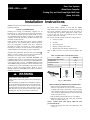
Refer to Table 1 and Fig. 1 for a list of parts included in this
kit.
Table 1—Wired Remote Controller Kit Contents
Item Quantity
RTX Wired Remote Controller 1
Display Cable 9 ft.
Attachment Screws 2
Anchors 2
Wall Control Circuit Board 1
Display Cable
9.2 ft in Length Room Controller Unit
(RTX) Wall Contro
l
Circuit Board
A06468
Fig. 1 − Kit Contents
INSTALLATION OF WIRED ROOM CONTROLLER
1. Select a location to mount the wall controller.
Since the wall controller is not used to sense temperature,
it should be placed in a location that is easily accessible
when changing settings and at a height where the display
can be easily seen (approximately 5 ft. above the floor and
within 9 ft. of the fan coil.)
2. Take the Room Controller (RTX) out of its packaging.
3. Mount the control on the wall, taking into account the
length of available cable (9 ft.).
NOTE: Common phone cable will not replace the cable
provided with the kit.
4. Connect the display unit cable to the RTX display unit
(see Fig. 2).

2
DISPLAY CABLE
RTX
RTX
Display Control Card
(New in the controller)
Remove the
display unit
cover
Screw to
fix unit
to wall
ON Button
Power ON
Light Display
2.8 meters
(9.2 ft)
RTX Display Unit
Insert the
display cable
into the RTX
display unit
A06469
Fig. 2 − Connecting Display Unit Cable
to RTX Display Unit
INSTALLATION OF DISPLAY ADAPTER CARD
1. Follow these instructions to install the wall control adapter
circuit board.
2. Installing the wired controller requires the replacement of
the existing circuit board with the wall control adapter
circuit board included in the kit.
3. Use the existing wireless remote to turn off the unit.
4. Disconnect the power supply.
ELECTRICAL SHOCK HAZARD
Failure to follow this warning could result in personal injury
or death.
Before beginning any modification or installation of this kit,
be sure the main electrical disconnect is in the OFF position.
Ensure power is disconnected to the fan coil unit. On some
systems both the fan coil and the outdoor unit may be on the
same disconnect. Tag the disconnect switch with a suitable
warning label. There may be more than one disconnect.
!WARNING
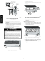
5. Remove the front grille (see Fig. 3)
A06470
Fig. 3 − Remove Front Grille
6. Carefully close the louvers.
7. Remove the two screws from the electrical box cover. (See
Fig. 4.)
FILTER
IR
RECEIVER
POWER/AIRCOND TIMER
FUSE
FUSE
AUTO/OFF
FILTER RESET
SERVICE LED
A06471
Fig. 4 − Remove Screws From Electrical Box Cover
8. Remove the electrical box cover.
9. Remove the two screws from above the air vents
(see Fig. 4).
NOTE: Some models have three screws.
10. On the bottom of the air conditioner, there are three
indicator triangles. Press gently on the triangles with a
downward motion (see Fig. 5).
FILTER
IR
RECEIVER
POWER/AIRCOND TIMER
FUSE
A06472
Fig. 5 − Press Downward on Indicator Triangles
11. Make sure that the louvers are closed. Remove the air
conditioner’s front panel and place it aside.
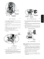
12. Remove the screw that holds the control unit in place (see
Fig. 6).
53DS−900−−−091

3
TH1
TH2
TH3
12346/N7*
Inter-unit
cable
Inter-unit
cable clamp
Power
cable
Power
cable
clamp
Screw attaching the
controller to the air-
conditioning unit
THI, TH2 and TH3
sensor connections to
the control unit
A06473
Fig. 6 − Control Unit
13. Use a screwdriver to release the end of the inter−unit cable
from its connectors (see Fig. 6).
14. Use a screwdriver to release the power cable ends from the
connectors (see Fig. 6).
15. Use a screwdriver to release the inter−unit cable from its
clamp.
16. Use a screwdriver to release the power cable from its
clamp.
17. Remove the TH1, TH2, and TH3 sensors from their
connection locations in the unit (see Fig. 6).
18. Pull the controller slightly outwards.
19. Disconnect the existing display card connections
(see Fig. 7.)
TH1
TH2
TH3
Display
Card
connecto
r
Card
g
ri
pp
in
g
tabs
A06474
Fig. 7 − Wall Control Adapter
20. Open the gripping tabs on each side and remove the
existing display card from its socket (see Fig. 7).
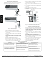
21. Thread the new display cable (included in the kit) through
the rear of the air−conditioner (adjacent to the entry for the
inter−unit cable) and through the space underneath the
display card (see Fig. 8).
TH1
TH2
TH3
Back of new card:
Insertion of the display
cable into the display
socket.
Return the display
connector to its
original location
Additional display
card connection;
previously hidden.
A06475
Fig. 8 − Threading Display Cable
22. Insert the end of the new display unit cable into the socket
located underneath the wall control adapter circuit board
(see Fig. 8).
23. Insert the ends of the two wiring harnesses into the
existing connectors located in upper part of the Display
Adapter Card (see Fig. 8).
24. Press down gently on the wall control adapter circuit
board to insert it into its proper position (to make this
easier, open the tabs on each side of the cardholder (see
Fig. 7).
DIPSWITCH SETTINGS
TH1
TH2
TH3
12346/N7*
123456
ON
123456
ON
123456
ON
Controlle
r
Lower right side of
the controller
Move DIP
switch 4 to the
OFF position.
A06477
Fig. 9 − Dipswitch Settings
NOTE: Only dipswitch 4 should be changed. All other switches
should remain in the position as shown on the sticker on the back
of the control unit.
1. Changes must be made to the position of dipswitch 4 in
the indoor unit’s control box to allow the air conditioner to
be operated by RTX room display unit fixed to the wall.
2. Remove the control box to permit access to the
dipswitches located in the lower part of the control box.
3. Move dipswitch number 4 to the OFF position
4. Replace the control back in its proper position
(see Fig. 9).
5. Reinstall control box and all connecting wires by
reversing steps 3 through 15 in the Installation section of
the display card.
53DS−900−−−091

4
INSTALLING RTX ROOM DISPLAY
The RTX display unit must be fixed to the wall. Do not locate the
RTX display unit underneath the indoor unit (see Fig. 10).
A06449
A06480
Fig. 10 − RTX Room Display
1. Remove the RTX display unit from its packaging.
2. Place the unit on the wall, taking into account the length
of available cable.
3. Connect the display unit cable to the RTX display unit
(see Fig. 8).
4. Connect the air−conditioner to the power supply and make
an initial check to ensure that everything is working
properly.
5. Check that the RTX display unit light is ON.
6. Press the ON button to start the air−conditioner working.
7. If the air−conditioner does not begin working, or is not
working properly, refer to the Troubleshooting section.
8. If the air−conditioner is working properly, turn it OFF and
disconnect it from the power supply.
9. Remove the cover from the RTX display unit (see Fig.
11).
10. Use the template to mark the position for drilling the hole
for the screw.
11. Press an anchor into the hole in the wall.
12. Use the screw to attach the RTX display unit onto the wall
(see Fig. 11).
DISPLAY CABLE
RTX
RTX
Display Control Card
(New in the controller)
Remove the
display unit
cover
Screw to
fix unit
to wall
ON Button
Power ON
Light Display
2.8 meters
(9.2 ft)
RTX Display Unit
Insert the
display cable
into the RTX
display unit
A06481
Fig. 11 − Connecting Display Unit Cable to RTX
TESTING AND TROUBLESHOOTING
1. If the RTX room display unit is working properly during
the initial check, perform a complete check as instructed in
the attached operating manual. Check the changes between
operating modes, changes in fan speed settings,
temperature adjustments, etc.
2. If necessary, the display can be changed from degrees
Celsius to degrees Fahrenheit (details in the operating
manual).
3. If the complete check reveals any malfunctions, refer to
the troubleshooting table in the operating manual.
4. If the air−conditioner is working properly, turn it OFF and
disconnect it from the power supply.
5. Refer to the section in this manual marked Installation of
Display Adapter Card and reverse steps 5 through 11.
6. Connect the air−conditioner to the power supply.
7. Turn the air−conditioner ON.
Table 2—Troubleshooting Table
Malfunction Possible Causes Recommended Solutions
RTX Display Unit is not lit (display OFF)
and the POWER indicator light is OFF
Faulty display unit cable (cable between the
control box and the RTX room display unit).
RTX room display unit malfunctioning.
Replace the display unit cable.
Replace the RTX room display unit.
RTX Display Unit is not lit (display OFF)
and the POWER indicator light is ON.
A beep can be heard every 20 seconds.
Faulty display unit cable (cable between the
control box and the RTX room display unit).
Dipswitches are not set properly.
Replace the display unit cable.
Check position of dipswitches according to
the sticker on the side of the control.
Dipswitch 4 should be in the OFF position.
Copyright 2006 CAC / BDP S 7310 W. Morris St. S Indianapolis, IN 46231
Manufacturer reserves the right to change, at any time, specifications and designs without notice and without obligations.
Catalog No: IIK−53DS900−5
Replaces: New
Printed in U.S.A. Edition Date: 08/06
53DS−900−−−091
-
 1
1
-
 2
2
-
 3
3
-
 4
4


Carrier 40BNC Installation guide
- Category
- Split-system air conditioners
- Type
- Installation guide
Ask a question and I''ll find the answer in the document
Finding information in a document is now easier with AI
Related papers
Other documents
-
ICP DAS USA DFS2A324J2A User manual
-
Wacker Neuson RTx-SC2 User manual
-
-
-
-
-
-
-
-
 Sim2 Multimedia RTX 55TV User manual
