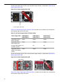
ARISTA DCS-7280CR3-32D4 User guide
- Category
- Network switches
- Type
- User guide


ii
© Copyright 2023 Arista Networks, Inc. The information contained herein is subject to change without notice. Arista Networks
and the Arista logo are trademarks of Arista Networks, Inc in the United States and other countries. Other product or service
names may be trademarks or service marks of others.
Headquarters
5453 Great America Parkway
Santa Clara, CA 95054
USA
+1 408 547-5500
www.arista.com
Support
+1 408 547-5502
+1 866 476-0000
Sales
+1 408 547-5501
+1 866 497-0000

Contents
Chapter 1: Overview.............................................................................1
1.1 Scope..................................................................................................................................1
1.2 Receiving and Inspecting the Equipment...........................................................................2
1.3 Installation Process.............................................................................................................2
1.4 Safety Information...............................................................................................................3
1.5 Obtaining Technical Assistance..........................................................................................3
1.6 Specifications...................................................................................................................... 3
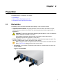
Chapter 2: Preparation.........................................................................9
2.1 Site Selection......................................................................................................................9
2.2 Tools and Parts Required for Installation......................................................................... 11
2.3 Electrostatic Discharge (ESD) Precautions...................................................................... 11
Chapter 3: Rack Mounting the Switch..............................................13
3.1 Two-Post Rack Mount (1RU)............................................................................................ 13
3.1.1 Attaching Mounting Brackets to the Chassis (Two-Post).....................................14
3.1.2 Inserting the Switch into the Rack (Two-Post).................................................... 15
3.2 Four-Post Rack Mount (1RU)........................................................................................... 15
3.2.1 Attaching Mounting Brackets to the Chassis (Four-Post)....................................17
3.2.2 Assembling the Rails onto the Equipment Rack.................................................18
3.2.3 Attaching the Switch to the Rack....................................................................... 19
3.3 Rack Mounting the Switch (2RU)..................................................................................... 20
3.4 Two-Post Rack Mount (2RU)............................................................................................ 21
3.5 Four-Post Rack Mount (2RU)........................................................................................... 21
3.5.1 Extracting the Brackets and the Rails.................................................................21
3.5.2 Attaching Mounting Brackets to the Chassis...................................................... 23
3.5.3 Expanding the Rails............................................................................................24
3.5.4 Assembling the Rails onto the Equipment Rack.................................................24
3.5.5 Attaching the Switch to the Rack....................................................................... 25
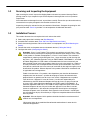
Chapter 4: Cabling the Switch.......................................................... 27
4.1 Grounding the Switch....................................................................................................... 27
4.2 Grounding Adapter Assembly (1RU)................................................................................ 27
4.3 Grounding Adapter Assembly (2RU)................................................................................ 29
4.4 Connecting Power Cables................................................................................................ 31
4.4.1 AC Power Supplies............................................................................................. 31
4.4.2 DC Power Supplies.............................................................................................32
4.5 Connecting Serial and Management Cables....................................................................34
Chapter 5: Configuring the Switch...................................................37
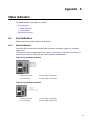
Appendix A: Status Indicators..........................................................39
A.1 Front Indicators.................................................................................................................39
A.1.1 Switch Indicators................................................................................................ 39
iv

Contents
A.1.2 Port Indicators.................................................................................................... 40
A.2 Rear Status Indicators......................................................................................................41
Appendix B: Parts List.......................................................................45
B.1 Accessory Kits..................................................................................................................45
B.2 Cables...............................................................................................................................50
B.3 Ground Extender Kit (Optional)........................................................................................50
Appendix C: Front Panel................................................................... 51
Appendix D: Rear Panel.....................................................................55
Appendix E: Maintenance and Field Replacement......................... 57
E.1 Considerations..................................................................................................................57
E.2 Power Supplies.................................................................................................................57
E.2.1 Removing a Power Supply................................................................................. 57
E.2.2 Installing a Power Supply................................................................................... 58
E.3 Fan Modules.....................................................................................................................58
E.3.1 Removing a Fan Module.................................................................................... 58
E.3.2 Installing a Fan Module...................................................................................... 59
Appendix F: Regulatory Model Numbers.........................................61
Appendix G: Taiwan RoHS Information...........................................63
v

Chapter 1
Overview
This guide is intended for properly trained service personnel and technicians who need to install
selected Arista Networks Data Center Switches.
The following topics are covered in this section:
•Scope
•Receiving and Inspecting the Equipment
•Installation Process
•Safety Information
•Obtaining Technical Assistance
•Specifications
1.1 Scope
This guide covers the following devices:
DCS-7280R3 Series
1RU Switches
DCS-7280PR3-24 DCS-7280PR3K-24 DCS-7280DR3-24 DCS-7280DR3K-24
DCS-7280CR3-32P4 DCS-7280CR3K-32P4 DCS-7280CR3K-32P4A DCS-7280CR3-32D4
DCS-7280CR3K-32D4 DCS-7280CR3K-32D4A DCS-7280CR3-36S DCS-7280CR3K-36S
DCS-7280CR3K-36A DCS-7280SR3-48YC8 DCS-7280SR3K-48YC8 DCS-7280SR3K-48YC8A
DCS-7280SR3-40YC6 DCS-7280SR3E-40YC6 DCS-7280TR3-40C6
2RU Switches
DCS-7280CR3-96 DCS-7280CR3K-96
DCS-7280R3A Series
1RU Switches
DCS-7280CR3A-24D12 DCS-7280CR3AM-24D12 DCS-7280CR3AK-24D12
2RU Switches
DCS-7280DR3A-54 DCS-7280DR3AM-54 DCS-7280DR3AK-54 DCS-7280DR3A-36
DCS-7280DR3AM-36 DCS-7280DR3AK-36 DCS-7280CR3A-48D6 DCS-7280CR3AM-48D6
DCS-7280CR3AK-48D6 DCS-7280CR3A-72 DCS-7280CR3AM-72 DCS-7280CR3AK-72
Important: Only qualified personnel should install, service, or replace this equipment.
Seul le personnel qualifié doit installer, service, ou remplacer cet équipement.
1

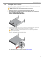
1.2 Receiving and Inspecting the Equipment
Upon receiving the switch, inspect the shipping boxes and record any external damage. Retain
packing materials if you suspect that part of the shipment is damaged; the carrier may need to
inspect them.
If the boxes were not damaged in transit, unpack them carefully. Ensure that you do not discard any
accessories that may be packaged in the same box as the main unit.
Inspect the packing list and confirm that you received all listed items. Compare the packing list with
your purchase order. Parts List provides a list of components included with the switch.
1.3 Installation Process
This section discusses the task required to install and use the switch.
1. Select and prepare the installation site (Site Selection).
2. Assemble the installation tools (Tools and Parts Required for Installation).
3. Attach the mounting brackets and install the switch in an equipment rack (Rack Mounting the
Switch).
4. Connect the switch to the power source and network devices (Cabling the Switch).
5. Configure the switch (Configuring the Switch).
Important: Class 1 Laser Product: This product has provisions to install Class 1 laser
transceivers which provide optical coupling to the communication network. Once a Class
1 laser product is installed, the equipment is a Class 1 Laser Product. The customer is
responsible for selecting and installing the Class 1 laser transceiver and for insuring that
the Class 1 AEL (Allowable Emission Limit) per EN/IEC 60825, CSA E60825-1, and Code
of Federal Regulations 21 CFR 1040 is not exceeded after the laser transceiver have
been installed. Do not install laser products whose class rating is greater than 1. Refer to
all safety instructions that accompanied the transceiver prior to installation. Only Class 1
laser devices, certified for use in the country of installation by the cognizant agency are to
be utilized in this product. Ultimate disposal of this product should be in accordance with
all applicable laws and regulations.
Produit Laser de classe 1: Ce produit a des dispositions pour installer des émetteurs-
récepteurs de laser de classe 1 qui offre de couplage au réseau de communication
optique.Une fois un produit laser de classe 1 est installé, l'équipement est un produit
Laser de classe 1 (Appareil à Laser de Classe 1).Le client est responsable pour
sélectionner et installer l'émetteur/récepteur de laser de classe 1 et pour assurer que
la classe 1 AEL (limite d'émission admissible) par EN/IEC 6-825, CSA E60825-1, et
Code des règlements fédéraux 21 CFR 1040 ne soit pas dépassée après avoir installé
l'émetteur/récepteur de laser. Ne pas installer des appareils à laser dont la cote de
classe est supérieure à 1.Voir toutes les consignes de sécurité qui ont accompagné
l'émetteur-récepteur avant l'installation. Seuls appareils laser de classe 1 certifiés pour
une utilisation dans le pays d’installation par l’organisme compétent doivent être utilisées
dans ce produit.
Important: Ultimate disposal of this product should be handled in accordance with all
national laws and regulations.
L'élimination finale de ce produit doit être effectuée conformément à toutes les lois
nationales etrèglements.
2

Overview
1.4 Safety Information
Refer to the Arista Networks document Safety Information and Translated Safety Warnings available
at: https://www.arista.com/en/support/product-documentation.
1.5 Obtaining Technical Assistance
Any customer, partner, reseller or distributor holding a valid Arista Service Contract can obtain
technical support in any of the following ways.
•Email: suppor[email protected]. This is the easiest way to create a new service request.
Include a detailed description of the problem and the output of “show tech-support”.
•Web: https://www.arista.com/en/support.
A support case may be created through the support portal on our website. You may also
download the most current software and documentation, as well as view FAQs, Knowledge Base
articles, Security Advisories, and Field Notices.
•Phone: +1 866-476-0000 or +1 408-547-5502.
Note:
No user serviceable parts inside. Refer all servicing to qualified service personnel.
Aucune pièce réparable par l'utilisateur à l'intérieur. Confiez toute réparation à un
technicien qualifié.
1.6 Specifications
List of specifications of Arista data center modular switches and components covered by this guide.
3

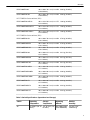
Table 1: Switch Specifications (Dimensions and Weights)
Switch Size (W x H x D) Weight
DCS-7280R3 Series switches (1RU)
DCS-7280PR3-24 48.3 x 4.4 x 58.2 cm (19 x 1.75
x 23.6 inches)
12.7 kg (28.0 lbs.)
DCS-7280PR3K-24 48.3 x 4.4 x 58.2 cm (19 x 1.75
x 23.6 inches)
12.7 kg (28.0 lbs.)
DCS-7280DR3-24 48.3 x 4.4 x 57.4 cm (19 x 1.75
x 22.6 inches)
13.1 kg (29.0 lbs.)
DCS-7280DR3K-24 48.3 x 4.4 x 57.4 cm (19 x 1.75
x 22.6 inches)
13.1 kg (29.0 lbs.)
DCS-7280CR3-32P4 48.3 x 4.4 x 55.8 cm (19 x 1.75
x 22.0 inches)
12.3 kg (27.0 lbs.)
DCS-7280CR3K-32P4 48.3 x 4.4 x 55.8 cm (19 x 1.75
x 22.0 inches)
12.3 kg (27.0 lbs.)
DCS-7280CR3K-32P4A 48.3 x 4.4 x 55.8 cm (19 x 1.75
x 22.0 inches)
12.3 kg (27.0 lbs.)
DCS-7280CR3-32D4 48.3 x 4.4 x 55.8 cm (19 x 1.75
x 22.0 inches)
12.3 kg (27.0 lbs.)
DCS-7280CR3K-32D4 48.3 x 4.4 x 55.8 cm (19 x 1.75
x 22.0 inches)
12.3 kg (27.0 lbs.)
DCS-7280CR3K-32D4A 48.3 x 4.4 x 55.8 cm (19 x 1.75
x 22.0 inches)
12.3 kg (27.0 lbs.)
DCS-7280CR3-36S 48.3 x 4.4 x 47.2 cm (19 x 1.75
x 18.6 inches)
10.5 kg (23.0 lbs.)
DCS-7280CR3K-36S 48.3 x 4.4 x 47.2 cm (19 x 1.75
x 18.6 inches)
10.5 kg (23.0 lbs.)
DCS-7280CR3K-36A 48.3 x 4.4 x 47.2 cm (19 x 1.75
x 18.6 inches)
10.5 kg (23.0 lbs.)
DCS-7280SR3-48YC8 48.3 x 4.4 x 46.7 cm (19 x 1.75
x 18.4 inches)
9.2 kg (20.2 lbs.)
DCS-7280SR3K-48YC8 48.3 x 4.4 x 46.7 cm (19 x 1.75
x 18.4 inches)
9.2 kg (20.2 lbs.)
DCS-7280SR3K-48YC8A 48.3 x 4.4 x 46.7 cm (19 x 1.75
x 18.4 inches)
9.2 kg (20.2 lbs.)
DCS-7280SR3-40YC6 48.3 x 4.4 x 46.9 cm (19 x 1.75
x 18.5 inches)
10.7 kg (23.6 lbs.)
DCS-7280SR3E-40YC6 48.3 x 4.4 x 46.9 cm (19 x 1.75
x 18.5 inches)
9.0 kg (20.0 lbs.)
DCS-7280TR3-40C6 48.3 x 4.4 x 46.9 cm (19 x 1.75
x 18.5 inches)
9.6 kg (21.1 lbs.)
DCS-7280R3 Series switches (2RU)
4

Overview
DCS-7280CR3-96 48.3 x 8.8 x 76.1 cm (19 x 3.50
x 30.0 inches)
23.6 kg (52.0 lbs.)
DCS-7280CR3K-96 48.3 x 8.8 x 76.1 cm (19 x 3.50
x 30.0 inches)
23.6 kg (52.0 lbs.)
DCS-7280R3A Series switches (1RU)
DCS-7280CR3A-24D12 48.3 x 4.4 x 59.2 cm (19 x 1.75
x 23.3 inches)
14.8 kg (32.6 lbs.)
DCS-7280CR3AM-24D12 48.3 x 4.4 x 59.2 cm (19 x 1.75
x 23.3 inches)
14.8 kg (32.6 lbs.)
DCS-7280CR3AK-24D12 48.3 x 4.4 x 59.2 cm (19 x 1.75
x 23.3 inches)
14.8 kg (32.6 lbs.)
DCS-7280R3A Series switches (2RU)
DCS-7280DR3A-54 48.3 x 8.8 x 76.4 cm (19 x 3.50
x 30.1 inches)
27.9 kg (61.6 lbs.)
DCS-7280DR3AM-54 48.3 x 8.8 x 76.4 cm (19 x 3.50
x 30.1 inches)
27.9 kg (61.6 lbs.)
DCS-7280DR3AK-54 48.3 x 8.8 x 76.4 cm (19 x 3.50
x 30.1 inches)
27.9 kg (61.6 lbs.)
DCS-7280DR3A-36 48.3 x 8.8 x 61.2 cm (19 x 3.50
x 24.1 inches)
24.1 kg (53.1 lbs.)
DCS-7280DR3AM-36 48.3 x 8.8 x 61.2 cm (19 x 3.50
x 24.1 inches)
24.1 kg (53.1 lbs.)
DCS-7280DR3AK-36 48.3 x 8.8 x 61.2 cm (19 x 3.50
x 24.1 inches)
24.1 kg (53.1 lbs.)
DCS-7280CR3A-48D6 48.3 x 8.8 x 68.4 cm (19 x 3.50
x 27.3 inches)
22.0 kg (48.6 lbs.)
DCS-7280CR3AM-48D6 48.3 x 8.8 x 68.4 cm (19 x 3.50
x 27.3 inches)
22.0 kg (48.6 lbs.)
DCS-7280CR3AK-48D6 48.3 x 8.8 x 68.4 cm (19 x 3.50
x 27.3 inches)
22.0 kg (48.6 lbs.)
DCS-7280CR3A-72 48.3 x 8.8 x 68.7 cm (19 x 3.50
x 27.0 inches)
22.4 kg (49.4 lbs.)
DCS-7280CR3AM-72 48.3 x 8.8 x 68.7 cm (19 x 3.50
x 27.0 inches)
22.4 kg (49.4 lbs.)
DCS-7280CR3AK-72 48.3 x 8.8 x 68.7 cm (19 x 3.50
x 27.0 inches)
22.4 kg (49.4 lbs.)
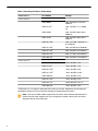
Table 2: Switch Specifications (Operational and Storage)
Switch Operating
Temperature Storage
Temperature Operating
Altitude Relative
Humidity
All 0° to 40°C (32° to
104°F)
-25° to 70°C (-13°
to 158°F)
0 to 3,000 meters
(0 to 10,000 feet)
5 to 90% (non-
condensing)
5

Table 3: Switch Specifications (Power Input)
Power Source PSU Models Ratings
Power Input: AC
PWR-500AC 100 - 240 VAC, 6.5 to 3.0 A,
50/60 Hz
PWR-511-AC1100 - 240 VAC< 7.1 A, 50/60
Hz
PWR-745AC 100 - 240 VAC 10.0 to 5.0 A
50/60 Hz
PWR-747AC 100 - 240 VAC 10.0 to 5.0 A
50/60 Hz
PWR-1011-AC1100 - 120 / 200 - 240 VAC 12 /
6 A 50/60 Hz
PWR-1511-AC1200 - 240 VAC 9.6 A 50/60 Hz
PWR-2411-AC1200 - 240 VAC 14 A 50/60 Hz
PWR-2421-HV 200 - 277 VAC 14 A 50/60 Hz
PWR-3001-AC 200 - 240 VAC 17 A 50/60 Hz
Power Input: DC
PWR-500-DC -48 to -60 VDC, 15 A
PWR-511-DC1-48 to -60 VDC, 13 A
PWR-1011-DC1-40 to -60 VDC, 30 A
PWR-1511-DC1-48 to -60 VDC, 39.5 A
PWR-1900-DC -48 to -60 VDC, 52 A
PWR-2411-DC1-48 to -60 VDC, 55 A
PWR-2421-HV 240 to 380 VDC, 13.5 A
PWR-3001-DC -48 to -60 VDC, 70 A
1 PWR-2421-HV is an optional alternative PSU. Check your switch, deployment and environment
compatibility before use in lieu of the PSU shipped and supported by your switch.
Note: Use only the PSU models supported by the switch. Some switches described in this
guide could use power supplies that may no longer be available. Contact your local Arista
representative for more information.
6

Overview
Table 4: Switch Specifications (Power Draw)
Switch Power Draw (Typical /
Maximum) Supported Power Supply
DCS-7280R3 Series switches (1RU)
DCS-7280PR3-24 650 W / 1100 W PWR-1511-AC, PWR-1511-DC
DCS-7280PR3K-24 650 W / 1100 W PWR-1511-AC, PWR-1511-DC
DCS-7280DR3-24 560 W / 1110 W PWR-1511-AC, PWR-1511-DC
DCS-7280DR3K-24 560 W / 1110 W PWR-1511-AC, PWR-1511-DC
DCS-7280CR3-32P4 535 W / 851 W PWR-1011-AC, PWR-1011-DC
DCS-7280CR3K-32P4 535 W / 851 W PWR-1011-AC, PWR-1011-DC
DCS-7280CR3K-32P4A 535 W / 851 W PWR-1011-AC, PWR-1011-DC
DCS-7280CR3-32D4 535 W / 851 W PWR-1011-AC, PWR-1011-DC
DCS-7280CR3K-32D4 535 W / 851 W PWR-1011-AC, PWR-1011-DC
DCS-7280CR3K-32D4A 543 W / 865 W PWR-1011-AC, PWR-1011-DC
DCS-7280CR3-36S 254 W / 423 W PWR-1011-AC, PWR-1011-DC
DCS-7280CR3K-36S 254 W / 423 W PWR-1011-AC, PWR-1011-DC
DCS-7280CR3K-36A 262 W / 437 W PWR-1011-AC, PWR-1011-DC
DCS-7280SR3-48YC8 155 W / 325 W PWR-511-AC, PWR-511-DC
DCS-7280SR3K-48YC8 155 W / 325 W PWR-511-AC, PWR-511-DC
DCS-7280SR3K-48YC8A 162 W / 338 W PWR-511-AC, PWR-511-DC
DCS-7280SR3-40YC6 130 W / 214 W PWR-511-AC, PWR-511-DC
DCS-7280SR3E-40YC6 130 W / 214 W PWR-511-AC, PWR-511-DC
DCS-7280TR3-40C6 186 W / 242 W PWR-511-AC, PWR-511-DC
DCS-7280R3 Series switches (1RU)
DCS-7280CR3-96 1003 W / 1803 W PWR-2411-AC, PWR-2411-DC
DCS-7280CR3K-96 1003 W / 1803 W PWR-2411-AC, PWR-2411-DC
DCS-7280R3A Series switches (1RU)
DCS-7280CR3A-24D12 TBD PWR-1511-AC, PWR-1511-DC
DCS-7280CR3AM-24D12 TBD PWR-1511-AC, PWR-1511-DC
DCS-7280CR3AK-24D12 TBD PWR-1511-AC, PWR-1511-DC
DCS-7280R3A Series switches (2RU)
DCS-7280DR3A-54 933 W / 1715 W PWR-3001-AC, PWR-3001-DC
DCS-7280DR3AM-54 933 W / 1715 W PWR-3001-AC, PWR-3001-DC
DCS-7280DR3AK-54 933 W / 1715 W PWR-3001-AC, PWR-3001-DC
DCS-7280DR3A-36 643 W / 1283 W PWR-2411-AC, PWR-2411-DC
7

DCS-7280DR3AM-36 643 W / 1283 W PWR-2411-AC, PWR-2411-DC
DCS-7280DR3AK-36 643 W / 1283 W PWR-2411-AC, PWR-2411-DC
DCS-7280CR3A-48D6 TBD PWR-1511-AC, PWR-1511-DC
DCS-7280CR3AM-48D6 TBD PWR-1511-AC, PWR-1511-DC
DCS-7280CR3AK-48D6 TBD PWR-1511-AC, PWR-1511-DC
DCS-7280CR3A-72 TBD PWR-1511-AC, PWR-1511-DC
DCS-7280CR3AM-72 TBD PWR-1511-AC, PWR-1511-DC
DCS-7280CR3AK-72 TBD PWR-1511-AC, PWR-1511-DC
8

Chapter 2
Preparation
The following topics are covered in this section:
•Site Selection
•Tools and Parts Required for Installation
•Electrostatic Discharge (ESD) Precautions
2.1 Site Selection
The following criteria should be considered when selecting a site to install the switch.
•Temperature and Ventilation: For proper ventilation, install the switch where there is ample
airflow to the front and back of the switch. The ambient temperature should not go below 0° or
exceed 40°C.
Important: To prevent the switch from overheating, do not operate it in an area where the
ambient temperature exceeds 40°C (104°F).
Pour empêcher l’interrupteur de surchauffe, ne pas utiliser il dans une zone où la
température ambiante est supérieure à 40°C (104°F).
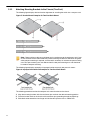
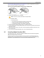
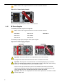
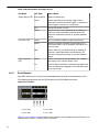
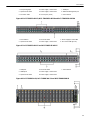
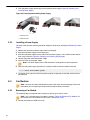
•Airflow Orientation: The fans and PSUs determine the airflow direction through the switch. The
color of the visible handles or labels indicate the airflow direction.
Note: The figures shown use representative Arista switches to illustrate airflow directions.
Refer to Rear Panel to determine the airflow for your switch.
•Blue Handle: Air Inlet module. The following figure shows the airflow through the switch with
air inlet modules:
Figure 1: Air Inlet Module
9

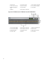
•Red Handle: Air Exit module. The following figure shows the airflow through the switch with
air exit modules:
Figure 2: Air Exit Module
Orient the switch such that the airflow through the switch is from the cooler to the hotter aisle.
If the airflow direction is not compatible with the installation site, reorient the fan modules to
circulate air in the opposite direction.
Rear Panel displays fan and power supply module locations on the rear panel. Red handles indicate
that they are air exit modules. Verify that each module has the same airflow direction. Base the
switch orientation on the airflow direction of the modules to assure the air inlet is always oriented
toward the cool aisle:
•Air Exit modules: orient the rear panel toward the hot aisle.
•Air Inlet modules: orient the rear panel toward the cool aisle.
If the airflow direction is not compatible with the installation site, contact your sales representative to
obtain modules that circulate air in the opposite direction.
•Rack Space: Install the switch in a 19" rack or cabinet. The switches covered by this guide
may be 1 RU or 2 RU in height. The accessory kit provides approved mounting brackets for the
system. Four-post mounting is recommended for all systems. Where 2-post parts are supplied,
they are intended for center-mounting the device.
When mounting the switch in a partially filled rack, load the rack from bottom to top, with the heaviest
equipment at the bottom. Load the switch at the bottom if it is the only item in the rack.
•Power Requirements: Power requirements vary by switch and power supply model. Table 3:
Switch Specifications (Power Input) and Table 4: Switch Specifications (Power Draw) provide
information regarding your specific system.
Two circuits provide redundancy protection. Cabling the Switch describes power cable
requirements.
Note: Handle or label color indicates airflow direction.
Important: The power input plug-socket combination must be accessible at all times; it
provides the primary method of disconnecting power from the system.
La combinaison de la puissance-prise d’entrée doit être accessible en tout temps ; Il
fournit le principal moyen de coupure d’alimentation du système.
•Other Requirements: Select a site where liquids or objects cannot fall onto the equipment and
foreign objects are not drawn into the ventilation holes. Verify these guidelines are met:
10

Preparation
• Clearance areas to the front and rear panels allow for unrestricted cabling.
• All front and rear panel indicators can be easily read.
• Power cords can reach from the power outlet to the connector on the rear panel.
Important: All power connections must be removed to de-energize the unit.
Toutes les connexions d’alimentation doivent être enlevées pour hors tension
l’appareil.
2.2 Tools and Parts Required for Installation
Each switch provides an accessory kit that contains parts that are required to install the switch.
In addition to the accessory kit, the following tools and equipment are required to install the switch:
Two-Post Rack
• Screws or rack mounting nuts and bolts.
• Screwdriver
Four-Post Rack (Tool-less)
No additional equipment required.
Four-Post Rack (Conventional)
• Screws or rack mounting nuts and bolts.
• Screwdriver
Accessory kit does not include screws for attaching the switch to the equipment rack. When
installing the switch into an equipment rack with unthreaded post holes, nuts are also required to
secure the switch to the rack posts.
2.3 Electrostatic Discharge (ESD) Precautions
Observe these guidelines to avoid ESD damage when installing or servicing the switch.
• Assemble or disassemble equipment only in a static-free work area.
• Use a conductive work surface (such as an anti-static mat) to dissipate static charge.
• Wear a conductive wrist strap to dissipate static charge accumulation.
• Minimize handling of assemblies and components.
• Keep replacement parts in their original static-free packaging.
• Remove all plastic, foam, vinyl, paper, and other static-generating materials from the work area.
• Use tools that do not create ESD.
11

12

Chapter 3
Rack Mounting the Switch
Rack Mounting the Switch (1RU)
The following topics are covered in this section:
•Two-Post Rack Mount (1RU)
Note: Use the rack-mount parts included with your switch for mounting. For heavier
switches, only a four-post mount is supported.
•Attaching Mounting Brackets to the Chassis (Two-Post)
•Inserting the Switch into the Rack (Two-Post)
•Four-Post Rack Mount (1RU)
•Attaching Mounting Brackets to the Chassis (Four-Post)
•Assembling the Rails onto the Equipment Rack
•Attaching the Switch to the Rack
Note: Four-post rack mount is recommended for all switches. Use the rack-mount parts
included with your switch for mounting. Rails from different kit SKUs may look similar but
could be incompatible leading to the inability to properly mount or remove a switch from the
rack.
The following sections detail rack mounting in two-post and four-post racks for 1 RU switches.
Important: The rack mounting procedure is identical for all switches covered by this guide.
Illustrations in this chapter depict the mounting of a DCS-7050QX-32S switch.
Les procédure de montage du bâti est identique pour tous les commutateurs visés
par ce guide. Illustrations dans ce chapitre montrent le montage d’un interrupteur de
DCS-7050QX-32S.
•Two-Post Rack Mount (1RU) provides instructions for mounting the switch in a two-post rack.
•Four-Post Rack Mount (1RU) provides instructions for mounting the switch in a four-post rack.
After completing the instructions for your rack type, proceed to Cabling the Switch.
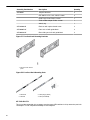
3.1 Two-Post Rack Mount (1RU)
To mount the switch onto a two-post rack, assemble the mounting brackets to the chassis, then
attach the brackets to the rack posts. Two-post accessory kits include the following two-post
mounting parts.
2 - Three-hole Mounting Brackets
Each chassis side has attachment pins that align with bracket holes. Pin orientation is symmetric
and equidistant, supporting bracket placements where the flange is flush with the front switch panel,
flush with the rear panel, or not flush with either panel. Each bracket hole includes a key-opening for
placing the bracket flush with the chassis and then locking it into place.
Important: Attachment pins must engage all three upper bracket holes.
Les goupilles de fixation doivent être bloquées tous les trois trous de la bride supérieure.
13

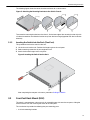
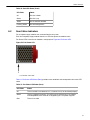
3.1.1 Attaching Mounting Brackets to the Chassis (Two-Post)
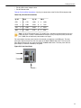
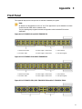
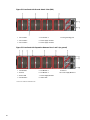
The following figure displays the front bracket alignment for attaching the switch into a two-post rack.
Figure 3: Bracket Mount Examples for Two-Post Rack Mount
Note: Deep and heavy devices could droop and cause damage to the equipment rack if front
or rear mounted. Arista recommends only center mounting for switches covered in this guide
when two-post mounting is required, and the switch accessory kit includes two-post mounting
ears. Four-post mounting ears are different from the two-post mounting ears and should not
be used for two-post mounting.
The following figure displays examples of improper bracket mounts for two-post rack mount.
Figure 4: Improper Bracket Mount Examples for Two-Post Rack Mount
The following procedure attaches the two-post rack mount brackets to the chassis.
1. Align the mounting brackets with the attachment pins to obtain the desired mounting position.
2. Place the bracket flush on the chassis with attachment pins protruding through key-openings.
3. Slide the bracket toward the front flange until the bracket clip locks with an audible click.
14

Rack Mounting the Switch
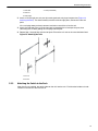
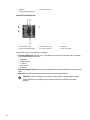
The following figures show the correct bracket attachment for a center mount.
Figure 5: Attaching the Mounting Brackets to the Switch Chassis
To remove the mounting bracket from the chassis, lift the front edge of the mounting bracket clip with
a flathead screwdriver and slide the bracket away from the front flange (opposite from the installation
direction).
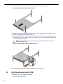
3.1.2 Inserting the Switch into the Rack (Two-Post)
This procedure attaches the switch to the rack.
1. Lift the chassis into the rack. Position the flanges against the rack posts.
2. Select mounting screws that fit your equipment rack.
3. Attach the bracket flanges to the rack posts.
Figure 6: Inserting the Switch into the Rack
After completing the two-post rack mount, proceed to Cabling the Switch.
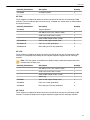
3.2 Four-Post Rack Mount (1RU)
The switch is mounted onto a four-post rack by assembling two rails onto the rear posts, sliding the
switch onto the rails, then securing the switch to the front posts.
The installation kit provides the following four-post mounting parts:
• 2 six-hole mounting brackets
15

• 2 rail-rods
• 2 rail-slides
The rail-rods and rail-slides assemble into two identical slide-rails.
Note: For longer chassis, there are two additional pieces to help the switch engage with the
rails earlier.
Each chassis side has attachment pins that align with bracket holes. Pin orientation is symmetric
and equidistant, supporting bracket placements where the flange is flush with the front switch panel,
flush with the rear panel, or not flush with either panel. Each bracket hole includes a key-opening for
placing the bracket flush with the chassis and then locking it into place.
Important: Attachment pins must engage at least five of the six bracket holes.
Goupilles de fixation doivent être lock au moins cinq des trous du six support.
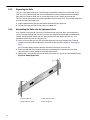
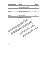
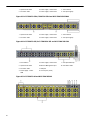
The following figure displays proper bracket mount configuration examples for four-post mounting.
Figure 7: Bracket Mount Examples for Four-Post Rack Mount
The following figure displays an improper bracket mount configuration example.
Figure 8: Improper Bracket Mount Example for Four-Post Rack Mount
16
Page is loading ...
Page is loading ...
Page is loading ...
Page is loading ...
Page is loading ...
Page is loading ...
Page is loading ...
Page is loading ...
Page is loading ...
Page is loading ...
Page is loading ...
Page is loading ...
Page is loading ...
Page is loading ...
Page is loading ...
Page is loading ...
Page is loading ...
Page is loading ...
Page is loading ...
Page is loading ...
Page is loading ...
Page is loading ...
Page is loading ...
Page is loading ...
Page is loading ...
Page is loading ...
Page is loading ...
Page is loading ...
Page is loading ...
Page is loading ...
Page is loading ...
Page is loading ...
Page is loading ...
Page is loading ...
Page is loading ...
Page is loading ...
Page is loading ...
Page is loading ...
Page is loading ...
Page is loading ...
Page is loading ...
Page is loading ...
Page is loading ...
Page is loading ...
Page is loading ...
Page is loading ...
Page is loading ...
Page is loading ...
-
 1
1
-
 2
2
-
 3
3
-
 4
4
-
 5
5
-
 6
6
-
 7
7
-
 8
8
-
 9
9
-
 10
10
-
 11
11
-
 12
12
-
 13
13
-
 14
14
-
 15
15
-
 16
16
-
 17
17
-
 18
18
-
 19
19
-
 20
20
-
 21
21
-
 22
22
-
 23
23
-
 24
24
-
 25
25
-
 26
26
-
 27
27
-
 28
28
-
 29
29
-
 30
30
-
 31
31
-
 32
32
-
 33
33
-
 34
34
-
 35
35
-
 36
36
-
 37
37
-
 38
38
-
 39
39
-
 40
40
-
 41
41
-
 42
42
-
 43
43
-
 44
44
-
 45
45
-
 46
46
-
 47
47
-
 48
48
-
 49
49
-
 50
50
-
 51
51
-
 52
52
-
 53
53
-
 54
54
-
 55
55
-
 56
56
-
 57
57
-
 58
58
-
 59
59
-
 60
60
-
 61
61
-
 62
62
-
 63
63
-
 64
64
-
 65
65
-
 66
66
-
 67
67
-
 68
68


ARISTA DCS-7280CR3-32D4 User guide
- Category
- Network switches
- Type
- User guide
Ask a question and I''ll find the answer in the document
Finding information in a document is now easier with AI