Page is loading ...

ASSEMBLY INSTRUCTIONS
OPERATOR’S MANUAL
PARTS LIST
29hp Truck
Loader with
Chipper
Actual product differs from product pictured above
Models covered:
TLBC29202BVG
Manual No. 3100026
R0808.1
Not for
Reproduction

1
preliminaries
Congratulations!
You have just purchased one of the finest pieces of outdoor power equipment on the market today. If properly
cared for, your new Giant-Vac truck loader will provide years of dependable service. Please read and follow
this instruction manual carefully in order to get the most out of your new equipment.
As you carefully uncrate your unit, you will find the following items:
1 Pallet containing:
1 Power Unit (with trailer frame and installed support jack and support leg if CHW unit)
1 Set of Fenders (CHW Units only)
1 Package containing taillamps and wiring harness
1 Package containing fender and wiring hardware
1 Hose/Parts Accessory Kit containing:
1 Discharge Stack
1 Discharge Elbow
1 8” dia. x 5’ Metal Discharge Hose
1 8” Squeeze Ring
1 10’ length of Intake Hose (10” dia. for 1601 units; 12” for 19-2501 units)
1 Intake Nozzle (10” for 1601 units; 12” for 19-2501 units)
1 Hose Support Band (10” for 1601 units; 12” for 19-2501 units)
1 Hose Support Boom Vertical Member
1 Hose Support Boom Horizontal Member
1 Support Boom Spring Guide with Spring and Spring Hardware installed
1 Package containing Assembly Hardware and two Hose Clamps (10” for 1601 units; 12”
for 19-2501 units)
1 Package containing operating manuals and warranty registration
Each product leaves our factory in excellent condition; occasionally, however, some damage may occur during
shipment. If any such damage is found upon initial inspection, immediately notify the transport carrier who
delivered your machine, as they are solely responsible for such damage, as well as any subsequent
adjustments necessary.
Before assembly, please take a moment and record your model number and serial number below for
future reference (both numbers are located on the silver tag adhered to the engine side of the impeller
housing assembly):
Model number_______________________________
Serial number________________________________
Also be sure to promptly fill out and return the warranty registration enclosed in your manual packet.
Your new loader requires very little assembly. Simply follow the instructions contained within this manual to
begin enjoying the benefits of your new unit.
CALIFORNIA PROPOSITION 65 WARNING
Gasoline and Diesel engine exhaust and some of its constituents are known to the State of California to cause cancer, birth defects and
other reproductive harm.
As an owner of off-road gasoline or diesel engine equipment and/or as an employer, you also may have an obligation under the
California Occupational Safety and Health Act or under Proposition 65 to warn persons exposed to gas and diesel engine exhaust
and/or other Proposition 65 chemicals in and around your workplace. See California Health and Safety Code section 25249.5, Title 22 of
the California Code of Regulations at Section 1200 er seq., and Title 8 of the California Code of Regulations Section 5194. R0603.1
Not for
Reproduction

2
safety rules regarding outdoor power equipment
PLEASE READ THE FOLLOWING BEFORE ASSEMBLING OR OPERATING UNIT
TRAINING
• Read, understand, and follow all instructions in the
manual and on the unit before starting. If the
operator(s) or mechanic(s) can not read English it is
the owner’s responsibility to explain this material to
them.
• Become familiar with the safe operation of the
equipment, operator controls, and safety signs.
• All operators and mechanics should be trained.
The owner is responsible for training the users.
• Only allow responsible adults, who are familiar
with the instructions, to operate the unit.
• Never let children or untrained people operate or
service the equipment. Local regulations may
restrict the age of the operator.
• The owner/user can prevent and is responsible for
accidents or injuries occurring to themselves, other
people or property.
PREPARATION
• Evaluate the terrain to determine what
accessories and attachments are needed to
properly and safely perform the job. Use only
accessories and attachments approved by the
manufacturer.
• Wear appropriate clothing including safety shoes,
safety glasses and ear protection. Long hair, loose
clothing or jewelry may get tangled in moving parts.
• Inspect the area where the equipment is to be
used and remove rocks or any other such objects
which can damage the machine or the receiver box.
• Use extra care when handling gasoline and other
fuels. They are flammable and vapors are
explosive.
a) Use only an approved container.
b) Never remove fuel cap or add fuel with the
engine running. Allow engine to cool before
refueling. Do not smoke.
c) Never refuel or drain the machine indoors.
• Check that operator’s presence controls, safety
switches and shields are attached and functioning
properly. Do not operate unless they are functioning
properly.
OPERATION
• Never run an engine in an enclosed area.
• Operate only in the daylight or with good artificial
light, keeping away from holes and hidden hazards.
• Be sure all components are securely in place and
in good operating order before starting engine.
• Be sure of your footing while using equipment,
especially when backing up. Walk, don’t run.
• Do not operate the unit without discharge
connected to a debris receiver box.
• Slow down and use caution when making turns
and when changing directions on slopes.
• Never leave a running unit unattended. Always
stop engine, and remove keys before leaving unit.
• Never operate without guards securely in place.
Be sure all safety features are attached, adjusted
properly and functioning properly.
• Never operate with intake or discharge
components loose, removed or altered.
• Do not change the engine governor setting or over
speed the engine.
• Stop on level ground, shut off engine before
leaving the operator’s position for any reason
including emptying the receiver box or unclogging
the intake or discharge.
• Stop equipment and inspect impeller blades after
picking up unusually large or hard objects or
abnormal vibration occurs. Make necessary repairs
before resuming operations.
• Keep hands and feet away from the intake and
discharge.
• Never carry passengers and keep pets and
bystanders away.
• Do not operate the unit while under the influence
of alcohol or drugs.
• Slow down and use caution when making turns
and crossing roads and sidewalks.
• Use care when hooking or unhooking the machine
to a towing vehicle.
• Use care when approaching blind corners, shrubs,
trees or other objects that may obscure vision.
Not for
Reproduction

2
safety rules regarding outdoor power equipment (cont.)
SLOPE OPERATION
Slopes are a major factor related to loss-of-control
and tip-over accidents, which can result in severe
injury or death. All slopes require extra caution. If
you cannot back up the slope, or if you feel uneasy
on it, do not operate on it.
Do
• Remove obstacles such as rocks, tree limbs, etc.
• Watch for holes, ruts, or bumps. Uneven terrain
could overturn the unit. Tall grass can hide
obstacles.
• Use slow speed.
• Keep all movement on the slopes slow and
gradual. Do not make sudden changes in speed or
direction.
Do Not
• Do not start or stop on a slope. If tires lose
traction, stop the unit and proceed slowly straight
down the slope.
• Do not turn on slopes unless necessary, and then,
turn slowly and gradually downhill, if possible.
• Do not operate near drop-offs, ditches, or
embankments. The operator could lose footing or
balance or unit could suddenly turn over if a wheel
is over the edge of a cliff or ditch, or if an edge
caves in.
CHILDREN
Tragic accidents can occur if the operator is not
alert to the presence of children. Children are often
attracted to the unit and its activity. Never assume
that children will remain where you last saw them.
• Keep children out of the operating area and under
the watchful care of another responsible adult.
• Be alert and turn unit off if children enter the area.
• Before and during reverse operation, look behind
and down for small children.
• Never carry children. They may fall off and be
seriously injured or interfere with safe unit
operation.
• Never allow children to operate the unit.
• Use extra care when approaching blind corners,
shrubs, trees, or other objects that may obscure
vision.
EMISSIONS
• Engine exhaust from this product contains
chemicals known, in certain quantities, to cause
cancer, birth defects, or other reproductive harm.
• Look for the relevant Emissions Durability Period
and Air Index information on the engine emissions
label.
MAINTENANCE AND STORAGE
• Always observe safe refueling and fuel handling
practices when refueling the unit after
transportation or storage.
• Always follow the engine manual instructions for
storage preparations before storing the unit for both
short and long term periods.
• Always follow the engine manual instructions for
proper start-up procedures when returning the unit
to service.
• Never store the machine or fuel container inside
where there is an open flame, such as in a water
heater. Allow unit to cool before storing.
• Shut off fuel while storing or transporting. Do not
store fuel near flames or drain indoors.
• Keep all hardware, especially impeller bolt, tight
and keep all parts in good working condition.
Replace all worn or damaged decals.
• Never tamper with safety devices. Check their
proper operation regularly.
• Clean debris from units, drives, mufflers, and
engine to prevent fires. Clean up oil or fuel spillage.
• Stop and inspect the equipment if you strike an
object. Repair, if necessary, before restarting.
• Never make adjustments or repairs with the
engine running unless specified otherwise.
• Park machine on level ground. Never allow
untrained personnel to service machine.
• Use jack stands to support components when
required.
• Carefully release pressure from components with
stored energy. (e.g. springs)
• Check impeller on a regular basis for bent, worn
or cracked blades. Only replace impellers; never
straighten or weld them.
• Keep hands and feet away from moving parts.
Not for
Reproduction

2
safety rules regarding outdoor power equipment (cont.)
• Belts and belt guard components are subject to
wear, damage, and deterioration, which could
expose moving parts or allow objects to be thrown.
Frequently check components and replace with
manufacturer’s recommended parts, when
necessary.
• Check operation of brake, tail and license lights
frequently. replace as required.
• Use only factory authorized replacement parts
when making repairs.
• Always comply with factory specifications on all
settings and adjustments.
• Only authorized service locations should be
utilized for major service and repair requirements.
• Never attempt to make major repairs on this unit
unless you have been properly trained. Improper
service procedures can result in hazardous
operation, equipment damage and voiding of
manufacturer’s warranty.
3
unit assembly & set-up
Note: Please refer to Parts List for correct part identification and placement. Parts list reference
numbers are called out by sheet number followed by reference number(s) on that sheet: (1:1) indicates
Sheet 1, reference number 1; (2:32,34-38) indicates Sheet 2, reference numbers 32 through 38 excluding
33; etc.
FENDER ASSEMBLY (CHW UNITS ONLY)
• Insert one 3/8-16 x 1” bolt, fitted with one 3/8”
flat washer, out through the three fender
mounting holes (two located in the diagonal
brace, one in the support leg channel).
• Attach fenders to sides of base, making sure
taillamp mounting brackets are toward rear of
unit as shown.
• Secure each fender with flat washers, 3/8” split
lock washers, and 3/8-16 hex nuts. Tighten
securely.
• Install one Taillamp assembly into the taillamp
mounting bracket of each fender, first by
inserting the rubber grommet into the bracket
hole, then pressing the taillamp firmly into the
grommet. (Taillamp wiring will be addressed
later.)
Not for
Reproduction

3
unit assembly & set-up (cont.)
AXLE ASSEMBLY (CHW UNITS ONLY)
Safety Note: Assistance is required when installing axle. If access to lifting equipment
is possible, it is highly recommended.
• Drop one 1/2-13 x 1-1/4” bolt, fitted with one
1/2” flat washer, down through the two
outermost axle mounting holes located in each
of the two channels that run lengthwise under
the engine base (two bolts each side, four bolts
total).
• Slide axle up onto bolts, making sure axle hubs
are offset toward rear of unit as shown.
• Secure assembly with four 1/2” flat washers,
1/2” split lock washers, and 1/2-13 hex end lock
nuts.
• Install tires onto axle hubs with lug nuts.
• Slide Support Leg up through leg channel,
hollow of leg facing out to accommodate fender
bolt, and secure in uppermost position with
clevis pin and bridge pin.
Use outermost holes
SUPPORT JACK AND SAFETY CHAIN INSTALLATION
(CHW UNITS ONLY)
Safety Note: Assistance is required when installing support jack. If access to lifting
equipment is possible, it is highly recommended.
• Remove jack from upside-down shipping
position. Lifting draw bar, insert jack into crank
assembly, making sure teeth of jack point out
as shown. Crank jack up into crank assembly
until unit sits level with ground, then drop
support leg (installed in previous assembly
step), and lock in lowermost position possible.
This will prevent possible unit rollover while
installing discharge assembly.
• Secure one Safety Chain onto each of the two
studs on either side of the draw bar front, with
one 1/2-13 reverse lock nut. Tighten snugly
while allowing free movement of chain link.
Note: fenders not
shown, to simplify
assembly diagram.
You may want to
attach fenders after
installing axle.
Not for
Reproduction
3
unit assembly & set-up (cont.)
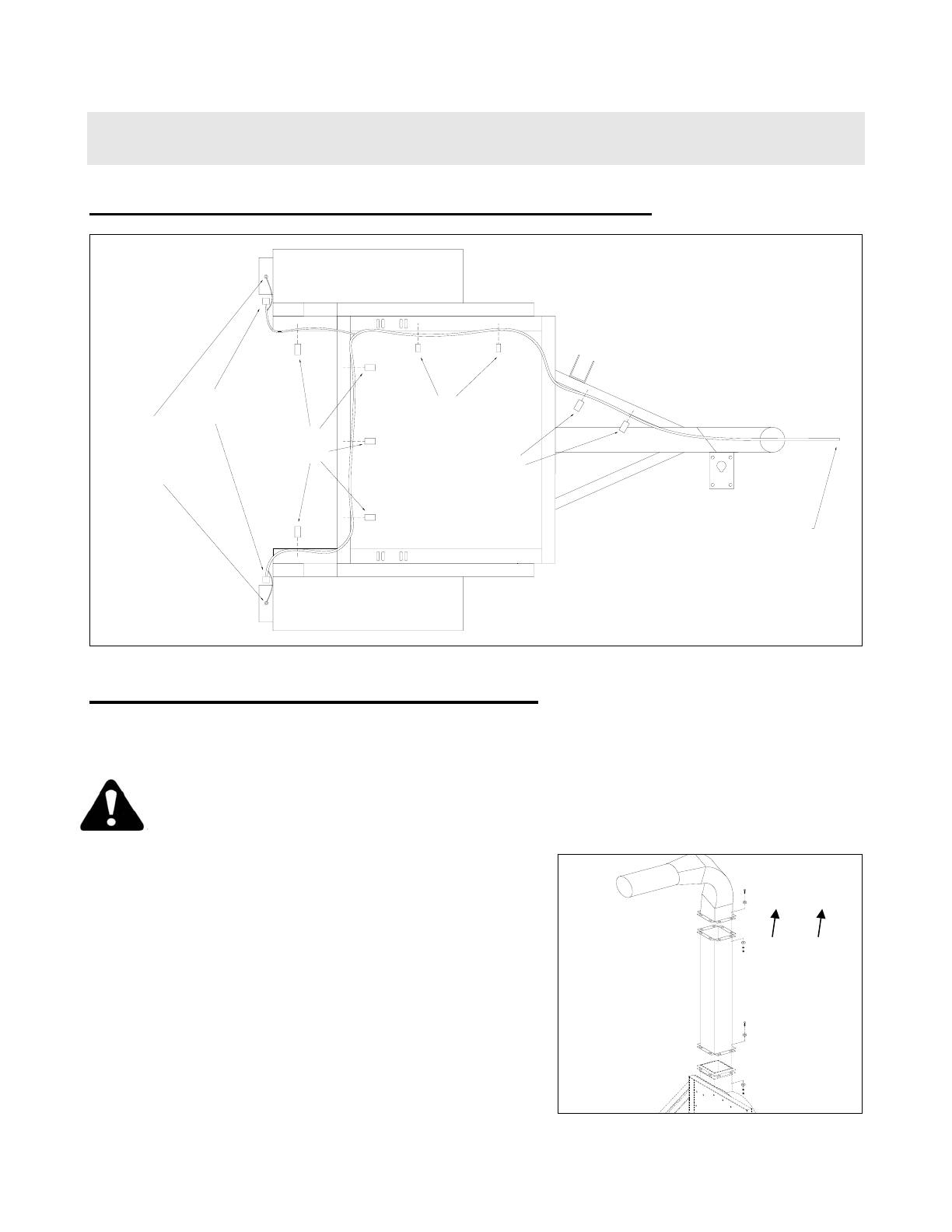
TRAILER WIRING SCHEME (CHW UNITS ONLY)
Trailer Wiring Scheme
(View from beneath unit)
Ground Strap -
fastens to bottom
of taillamp mounting
bracket with #10 x .50
self-drilling screw
Taillamp Plug -
Plugs into Taillamp
Large Harness Clips (5) -
Fastens harness to unit
Small Harness Clips (2) -
Fastens harness to unit
Large Harness Clips (2) -
Fastens harness to unit
Install Plug for connection with Vehicle (Plug Not Included)
Trailer Plug
Wiring Code:
Red - Right signal
Yellow - Left signal
Brown - Taillights
Green - Ground
DISCHARGE ASSEMBLY (ALL UNITS)
Safety Note: Assistance is required when installing discharge stack and elbow. If
access to lifting equipment is possible, it is highly recommended.
Important Safety Note: To prevent unit rollover during Discharge Assembly,
lock rear support leg in lowermost position possible. Failure to do this may
result in injury or death and/or damage to unit or property.
• Place discharge stack atop power unit, with
boom pivot brackets facing out toward right rear
of unit (from driver’s perspective). Insert eight
3/8-16 x 1-1/4” hex bolts (3:2), each fitted with
one flat washer (3:3), through bolt flange holes,
securing with flat washers, lock washers and
nuts (3:3-5). Tighten securely.
• Attach discharge elbow (3:1) to top of stack,
with discharge directed toward towing hitch,
using same hardware as in above step.
Tighten securely.
Boom pivot
brackets on
stack should
face toward right
rear
of unit
Not for
Reproduction
3
unit assembly & set-up (cont.)
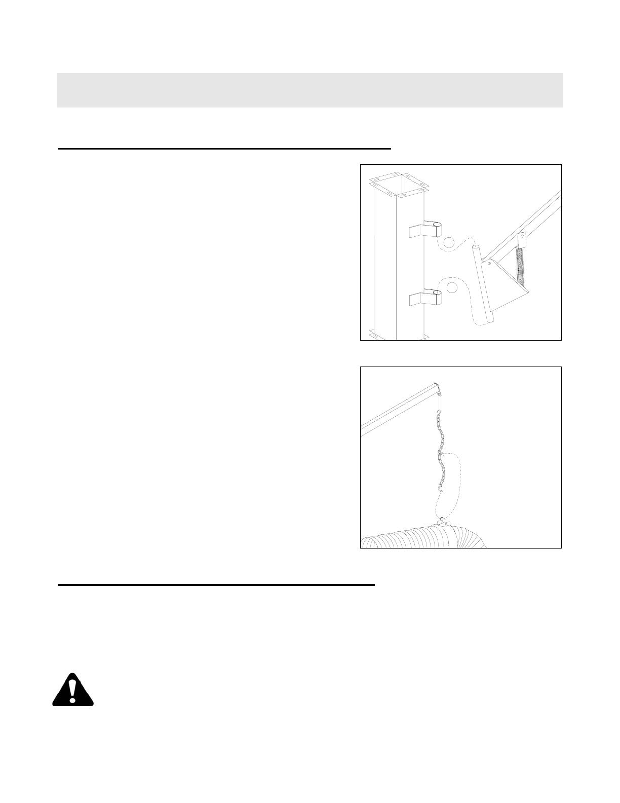
HOSE SUPPORT BOOM ASSEMBLY (cont.)
• Lift boom assembly and install into boom pivot
brackets on discharge stack, first slipping top
portion of vertical boom member into top
bracket on stack, then dropping bottom portion
into bottom bracket.
1
2
• Catch S-hook on one end of boom support
chain (5:9) into chain eye at end of horizontal
boom member.
• Slip other end of chain through eye clip atop
hose support band, then adjust chain length
between hose and boom to about three feet
(3/4 of total length) by slipping S-hook on end
of chain through appropriate mid-link.
BATTERY SERVICE AND CONNECTIONS
• Fill battery with acid (auto parts store).
• Connect battery cables (hardware not supplied), making careful note of polarity:
Long cable from engine goes to battery positive (+)
Short cable bolted to engine base next to battery box goes to battery ground (-)
• Slip terminal covers on cables over battery terminals
Important Safety Note: Incorrect battery cable connection can result in
personal injury or equipment damage.
Not for
Reproduction

3
unit assembly & set-up (cont.)
DEBRIS BOX CONSTRUCTION
WARNING: This unit is designed to be used in conjunction with a debris collection
box. NEVER run or operate your Truck Loader without a debris box.
Below are directions for constructing a simple, sturdy debris box for use in a standard pickup
bed:
• Cut four pieces of 3” angle iron to the inside length of the truck bed, four pieces to the inside width, then four
pieces that measure from the truck bed floor to approximately 8” higher than the top of the unit discharge
when the unit is connected to the truck. Either weld or securely bolt the box frame together.
• Line the inside front and sides with 3/4” exterior grade plywood.
• Cover the top of the frame with a heavy duty mesh screening to allow for adequate ventilation.
• Cut a plywood door the width and height of the box frame. Install a heavy duty hinge at the top of the door
and fasten it to the rear of the box frame. Install latches or other locking mechanisms between the lower
sides of the door and the box sides to keep the door from opening inadvertently.
• Mark the location on the door where the unit discharge meets the box, then cut a 16” diameter hole in the
door at that location. Install a rubber gasket around the hole to prevent debris blow-by – an old 13” or 14”
inner tube works fine.
CONNECTING UNIT TO TOWING VEHICLE
• Install appropriate trailer plug onto end of unit wiring harness to match socket on towing vehicle. Wiring
scheme is as follows:
Red – Right signal
Yellow – Left signal
Brown – Taillights
Green – Ground
• Back towing vehicle up to unit. Raise or lower support jack until ball hitch receiver on unit is about 3-4”
higher than ball hitch on vehicle. Flip lock lever up on ball hitch receiver.
• With assistance behind, back up slowly, aligning both ball hitch receiver with ball hitch and discharge hose
with receiver box opening.
• Lower front of unit down until ball hitch receiver drops completely onto ball hitch. Rock unit back and forth a
couple of times to ensure full coupling of ball hitch. Lock ball hitch receiver lever. Use a clevis pin or
padlock through locking hole in lever, to prevent accidental disconnect.
• Connect safety chains to vehicle in a criss-cross fashion to cradle draw bar in case of accidental disconnect,
then connect wiring harness plug into trailer socket of vehicle.
• Lift rear support leg and secure in uppermost position with clevis pin. Also be sure to fully raise support
jack.
Note: To prevent possible rollover, lock rear support leg in lowermost position
possible when unit is parked or disconnected from towing vehicle.
Your unit is now ready to be started and checked for proper operation. See your engine
manual for proper engine prep and operation.
Not for
Reproduction
3
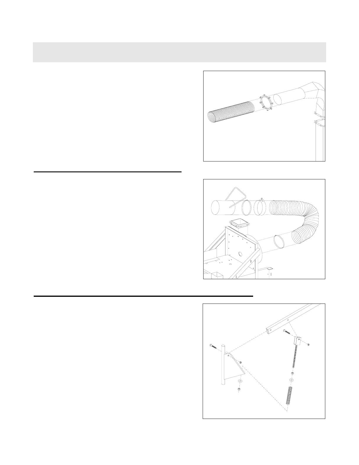
unit assembly & set-up (cont.)
• Slip one end of metal discharge hose (3:6) onto
barrel of discharge stack.
• Secure hose in place with squeeze ring (3:7),
tightening all bolts securely enough to dimple
hose against barrel of stack and thereby
prevent slippage of hose on stack assembly.
INTAKE ASSEMBLY (ALL UNITS)
• Slip one hose clamp (2:9) onto one end of
intake hose (2:8), then slip end of hose onto
intake flange barrel (2:5), located in front of
impeller housing. Tighten clamps securely.
• Slip Hose support band (2:10) about half-way
up the length of the hose, with eye clip facing
up.
• Slip one hose clamp onto free end of intake
hose, followed by Intake Nozzle (2:11) with
handle pointed upwards and toward hose.
Tighten clamps securely.
HOSE SUPPORT BOOM ASSEMBLY (ALL UNITS)
• Attach yoke end of Threaded spring guide (5:5)
to second thru hole of horizontal boom member
(5:2) with one 1/2-13 x 3” hex bolt (5:3),
securing with 1/2-13 lock nut (5:4). Do not over
tighten lock nut. Note: Be sure spring guide
and chain eye at end of boom are both toward
bottom of boom member.
• Attach horizontal boom member to vertical
boom member (5:1) with one 1/2-13 x 3” hex
bolt, securing with 1/2-13 lock nut. Do not over
tighten lock nut. Be sure spring guide is toward
base of vertical boom member.
• Remove 3/4” hex nut and flat washer (5:6-7)
from bottom of threaded spring guide. Slip
thread down through hole in base of vertical
boom member, securing with same hardware
as previously removed.
Not for
Reproduction

4
unit operation
GENERAL GUIDELINES TO OBSERVE DURING OPERATION
• Never allow a person to ride, sit or stand on the unit. Never allow a person to ride, sit or stand
on the towing vehicle other than in the driver’s cab of the towing vehicle.
• Make sure that the driver of the towing vehicle has the operator of the unit in full view at all
times. Also, when operating the unit, instruct the operator to stay to the side of the machine,
never in front or behind.
• Collecting debris into piles for the machine to intercept prior to startup will save time and fuel
as well as wear and tear on the unit.
• We recommend the following for the most efficient performance: if debris is very dry, run the
machine at approximately half throttle; this will help reduce the amount of small particles of
debris escaping through the ventilation screen. If debris is wet or partially frozen, run the
machine at full throttle.
• Lower intake hose boom assembly until nozzle floats 2-3 inches from the ground, then adjust
engine throttle so that when nozzle is pushed to the ground, suction can be broken with
moderate effort using three fingers of one hand. This will make operation relatively easy and
comfortable.
• Time and experience will be your best guide in finding the most efficient performance from
your unit.
UNCOUPLING UNIT FROM TOWING VEHICLE
• Disconnect taillight/brakelight plug from towing vehicle receiver.
• Unhook safety chains from rear of towing vehicle.
• Unlock ball hitch receiver lever on unit and flip lever up.
• Crank down wheel jack until ball hitch receiver on unit clears ball hitch on towing vehicle.
• Drop rear support leg to lowermost position and secure with clevis and bridge pin. Note:
Failure to follow this step can result in unit rollover and serious personal injury and unit
damage.
• Pull vehicle away from unit.
Not for
Reproduction

5
unit maintenance
GENERAL MAINTENANCE
NOTE: Some maintenance services, such as engine repairs, electrical repairs, etc., should be
performed only by a qualified technician.
• Check overall condition of unit prior to each use, repairing or replacing worn, damaged or
missing components promptly. Check all fasteners regularly and tighten if necessary.
• Follow engine manufacturer’s recommendations for maintenance schedules. Use only
recommended parts, fluids and lubricants. Failure to follow manufacturer’s recommendations
may void manufacturer’s warranties.
• Lubricate impeller shaft bearings every 50 hours of operation. Use a high quality bearing
grease, available from your local dealer (or auto parts store).
• Maintain tire pressure as indicated on tire sidewall. Replace worn or damaged tires promptly.
• Keep engine free from a buildup of grass, leaves or excessive grease. An accumulation of
these combustible materials may result in a fire, or simply impede performance.
• Never change attachments or make any adjustments, repairs or replacements until the unit is
completely shut down and the battery is disconnected.
CHECKING AND ADJUSTING IMPELLER BELTS
NOTE: Check new belts frequently during first 24-48 hours of installation, as tension will
decrease significantly due to belt seating.
To obtain optimum performance and longer life from your belts, check and adjust tension using a belt
tension checker, available at any auto parts dealer.
• Remove drive belt top cover.
• Take an initial tension check. Good belt tension is generally between 8-10 lbs. With a 3/8”
deflection.
• If adjustment is needed, loosen the four engine mounting bolts. Do not completely remove
bolts.
• Loosen the two threaded tensioning rods opposite the impeller side of the engine, making
sure to loosen both the same number of turns in order to avoid misaligning the engine.
Not for
Reproduction

5
unit maintenance (cont.)
CHECKING AND ADJUSTING IMPELLER BELTS (cont.)
• Increase belt tension by slowly tightening the two threaded tensioning rods on the impeller
side of the engine, making sure to tighten both the same number of turns in order to avoid
misaligning the engine. Recheck tension every turn or so until desired tension is achieved.
• Retighten engine mounting bolts securely, then check and tighten all tensioning rods to avoid
loosening and consequential loss.
• Replace drive belt top cover.
REPLACING IMPELLER BELTS
IMPORTANT NOTE: IT IS HIGHLY RECOMMENDED THAT IMPELLER BELTS BE
REPLACED BY AN AUTHORIZED GIANT-VAC DEALER.
STORAGE
• Keep the unit in locked storage to prevent unauthorized individuals, especially children, from
playing and/or tampering with the unit.
• When storing the unit for prolonged periods, it is recommended to disconnect the battery.
• Store fuel in an approved, clearly marked container.
• DO NOT store gasoline power equipment or fuel containers in any closed area where heat-
radiating appliances or open pilot lights are present, unless the fuel has been completely
drained from the power equipment and the fuel containers.
REPLACEMENT PARTS
Replacements parts are available from your local Giant-Vac dealer.
Not for
Reproduction

CHIPPER ATTACHMENT
SAFETY INFORMATION
Giant-Vac has done everything imaginable to design the safest machines possible. However,
machine safety depends on the operator and how well operators follow the Giant-Vac safety
guidelines provided in the owner’s manual. The following information highlights the safety procedures
recommended by Giant-Vac for all hand-fed brush chippers.
The information is divided into four safety categories: 1) Proper Clothing and Protective Equipment 2)
Pre Start-Up Procedures 3) Chipper Operation Safety and 4) Chipper Maintenance and Care Safety.
Proper Clothing and Protective Equipment: Every operator should wear proper clothing and
protective equipment on the job.
• Clothing should be close fitting and tucked in. Operator’s should not wear loose fitting clothing
like scarves and untucked or unbuttoned shirts and jackets, and pants with cuffs, which could
get caught on brush while they are chipping.
• A hardhat and ear protection is required.
• Eye protection is also required. All eye protections must be OSHA approved and may consist
of glasses, goggles or a flip down visor that may be plastic or mesh.
• Operators must wear a sturdy pair or work pants and a good pair of hard-toe work boots with
non-slip soles.
• Gloves are recommended to protect the operators’ hands, but gauntlet style gloves should
never be worn, again due to possibility of snagging on wood being chipped.
• Operators must avoid wearing any kind of jewelry such as earrings, rings, watches or
necklaces that could present a safety hazard.
• Operators must always remove their saddlebag, body belt or harness before operating the
chipper.
Pre Start-Up Procedures: Before chipping brush, operators should read and understand all safety
information in the operator’s manual provided with their chipper.
• Operators should understand all decals on the chipper and never remove them. If the decals
are flayed or worn, they should be replaces.
• To attach a chipper for towing, operator’s should:
1. Inspect the hitch before hooking up to the tow vehicle.
2. Determine if the Ball Hitch is worn and replace it if it is.
3. Make sure the hook is latched and the safety chains are attached properly.
4. Hook the chains to the vehicle by crossing the chains under the tongue, allowing
enough slack to avoid binding when making turns.
5. Make sure the jack is raised and then attach electrical connector to the towing vehicle.
Not for
Reproduction

6. Check air tire pressure.
7. Make sure the chipper is level for towing.
• When chipper arrives at site, never set up the chipper under the tree to be pruned, cut or
worked on, and whenever possible, the chipper should be set up on level ground.
• If a machine is hitched to a vehicle, make sure the hitch is secure and the safety chain is
properly attached. If it isn’t hitched to a vehicle, make sure the tongue is blocked.
• Wheel chocks should be placed under both wheels to keep the chipper from moving.
• Operator should do a pre-start walk around inspection of the machine each day before it is
used, checking the following:
1. Nuts, bolts, and belts to make sure they are tight
2. Infeed, to make sure nothing is obstructing the opening
3. All fluid levels, including engine oil
• Always remove the ignition key before servicing the chipper.
• Check knives for sharpness and cracks. When performing knife maintenance, always wear
proper gloves. Remove the chipper chute roll impeller to inspect the knives and when
finished, close the chute.
• Make sure the discharge chute is pointed in the proper direction, away from buildings, by
standers and operators.
Chipper Operation Safety: Safe operation of the chipper is crucial.
• Maximum diameter of material to be feed into the chipper shall be 2-1/2” and shall not exceed
6 feet in length, avoid dead or frozen wood in order to avoid kickback.
• Brush for the chipper should be stacked in a way that makes it easy and convenient for the
operator to feed the chipper. The butt-ends of the brush should face the chipper infeed. Place
the brush stacks at a good distance from the chipper to allow the operator a clear path.
• Before starting the chipper, make sure all personnel are clear of the machine and the chip
discharge chute is pointed in a safe direction.
• When starting the machine, always idle the engine to warm it up, and then raise the engine
RPM to full throttle. Operator should always make sure the chipper is at full throttle when
chipping to insure proper discharge of material and to avoid plugging problems.
• Operators should never operate the machine while under the influence of drugs or alcohol or
while taking medication that might impair the operator’s ability to concentrate.
• Feed the brush into the chipper butt-end first.
Not for
Reproduction

• The operator should never, under any circumstances, place their feet or hands in the infeed
chute while the machine is running. An operator should never, for any reason, kick brush in
with the feet. To safely feed short material, always lay the short material on top of longer
material that is feeding.
• Never attempt to feed handfuls of twigs, leaves and other material that has been raked up.
This material should be placed in the chip van or chip pile directly. Not only is it dangerous to
feed the material, but also it can contain rocks, metal and other material that can damage the
chipper.
• Always examine the brush pile for foreign objects before chipping.
• Remove the ignition key when the machine is left unattended.
• Have a first-aid kit on-site, along with a fire extinguisher.
Chipper Maintenance and Care Safety: Maintenance is key to keeping the Giant-Vac chipper in
excellent condition. As important as maintenance upkeep is to the chipper, it is equally important to
perform all maintenance is a safe manner.
• Never attempt to unclog a chipper or perform any type of maintenance while the chipper is
running.
• Before performing any maintenance, turn off the engine and remove the ignition key.
• Let the impeller come to a complete stop before opening the chipper door. The chipper
impeller will coast for several minutes after the machine is shut off.
• Once it has stopped coasting, make sure all locking devices are in their proper place before
performing maintenance.
• Giant-Vac recommends a torque wrench be used during maintenance to assure that bolts are
at their proper tightness.
• When refueling, make sure there is no open flame or source of a spark in the vicinity of the
machine.
Not for
Reproduction

Not for
Reproduction
Not for
Reproduction

Giant-Vac Model TLBC29202BVG Chippe
r
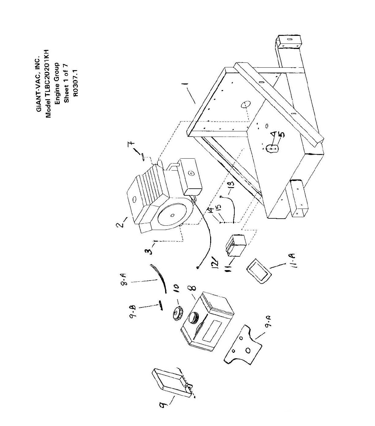
Sheet 1 - ENGINE GROUP
REF. PART
NO. NO. DESCRIPTION
T
LBC29202BVG
1 10196 En
g
ine Base 1
2 39044 29h
p
Bri
gg
s & Stratton En
g
ine 1
-- 39231 Muffler
,
Exhaust Ass
y
1
-- 32301 Elbow
,
Exhuast 90-De
g
ree 1
-- 32302 Ca
p,
Rain Exhaust 1
-- 32303 Clam
p,
Muffler 1
3 31747 3
/
8 x 2" Hex Bolt
(
Motor Mount Bolt
)
3
3 31595 3
/
8 x 1-3
/
4" Hex Bolt
(
Motor Mount Bolt
)
1
4 31008 3
/
8 Lock Washe
r
4
5 31009 3
/
8 Hex Nu
t
4
8 40117 Fuel Tan
k
1
8
A
31755 Hose
,
Rubber Fuel 1
/
4" x 10" Len
g
th 1
-- 34041 Clam
p,
Hose 1
/
4" Worm Drive 2
9 31157 Fuel Tank Stra
p
2
9
A
31158 Gas Tank Moun
t
1
9B 31445 Inline Fuel Shutoff Valve 1
10 40119 Fuel Tank Ca
p
1
11 39020 Batter
y
1
11
A
40118 Batter
y
Box 1
-- 31642 Batter
y
Cable - 32SS
(
Positive
)
1
-- 31836 Batter
y
Terminal Cover - Red 1
-- 31643 Batter
y
Cable - 16SS
(
Ground
)
1
-- 31837 Batter
y
Terminal Cover - Black 1
Not for
Reproduction

Not for
Reproduction
/