A DIVISION OF DOUGLAS DYNAMICS, L.L.C.
November 1, 2003
Lit. No. 28047
3713
TRUCK MOUNT
Installation Instructions
for
Personal Plow
Jeep Liberty 2003 – 20__
CAUTION
Read this document before installing the
snowplow.
CAUTION
See your sales outlet for application
recommendations. The Kit Selection Guide/
Selection List has specific vehicle and
snowplow requirements.

November 1, 2003 2 Lit. No. 28047
3713
NOTE: Identifies tips, helpful hints, and
maintenance information the owner/operator
should know.
SAFETY DEFINITIONS WARNING/CAUTION AND INSTRUCTION
LABELS
Become familiar with and inform users about the
warning label and instruction label on the back of the
blade.
Warning and Caution Label
Instruction Label
27155
ON
OFF
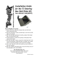
Connecting
Pin
Jack
Retainer
Jack
Sleeve
Jack
Jack
Handle
Plow Gear
Receiver
Assembly
Attachment
Arm
U.S. Patents 4,999,935; 5,420,480; 6,253,470; RE35,700; CAN Patent 2,060,425; and other patents pending.
Read Owner's Manual for Complete Instructions
4. Loosen one jack handle and
slide jack sleeve down below
jack retainer. Remove jack and
retighten jack handle. Repeat
for other jack and store them.
5. Connect all electrical cables from
vehicle to snowplow.
1. Make certain both connecting
pins are fully retracted.
2. Drive vehicle slowly to completely
insert attachment arms into
receiver assembly slots.
3. Twist both connecting pins to
release spring tension, then
push plow gear toward vehicle
so connecting pins fully
engage holes in attachment
arms.
ATTACH
INSTRUCTIONS
3. While pushing plow gear toward
vehicle to release connecting pin
tension, pull connecting pin out
on one side and twist pin handle to
keep pin retracted. Repeat
procedure for other connecting
pin.
4. Disconnect all electrical cables.
DETACH
INSTRUCTIONS
1. Put blade on ground using LOWER/
FLOAT on snowplow control. Leave
control ON and in FLOAT.
2. Attach jacks. Loosen jack handle,
put jack on ground, and raise jack
sleeve until fully engaging jack
retainer. Tighten jack handle.
Repeat for other jack.
5. Back vehicle away from
snowplow.
6. See Owner's Manual for proper
snowplow storage.
This snowplow is for personal/homeowner use only.
This snowplow is for personal/homeowner use only.
This snowplow is for personal/homeowner use only.
CAUTION
Indicates a situation that, if not avoided, could
result in damage to product or property.
WARNING
Indicates a potentially hazardous situation that,
if not avoided, could result in death or serious
personal injury.

Lit. No. 28047 3 November 1, 2003
3713
PERSONAL SAFETY
• Wear only snug-fitting clothing while working on
your vehicle or snowplow.
• Do not wear jewelry or a necktie, and secure long
hair.
• Wear safety goggles to protect your eyes from
battery acid, gasoline, dirt, and dust.
• Avoid touching hot surfaces such as the engine,
radiator, hoses, and exhaust pipes.
• Always have a fire extinguisher rated BC handy, for
flammable liquids and electrical fires.
SAFETY PRECAUTIONS
Improper installation and operation could cause
personal injury and/or equipment and property damage.
Read and understand labels and the Owner’s Manual
before installing, operating, or making adjustments.
Be careful when using gasoline. Do not use gasoline to
clean parts. Store only in approved containers away
from sources of heat or flame.
FIRE AND EXPLOSION
CAUTION
To prevent accidental movement of the blade,
always turn the ON/OFF switch to OFF
whenever the snowplow is not in use. The
control indicator light will turn off.
CAUTION
Refer to the Kit Selection Guide/Selection List
for minimum vehicle recommendations and
ballast requirements.
WARNING
Gasoline is highly flammable and gasoline
vapor is explosive. Never smoke while
working on a vehicle. Keep all open flames
away from gasoline tanks and lines. Wipe up
any spilled gasoline immediately.
WARNING
Lower blade when vehicle is parked.
Temperature changes could change hydraulic
pressure, causing the blade to drop
unexpectedly or damaging hydraulic
components. Failure to do this can result in
serious personal injury.
WARNING
Remove blade assembly before placing
vehicle on hoist.
WARNING
The driver shall keep bystanders clear of the
blade when it is being raised, lowered, or
angled. Do not stand between the vehicle and
the blade or within 8 feet of a moving blade. A
moving or falling blade could cause personal
injury.
WARNING
Keep hands and feet clear of the blade and
A-frame when mounting or removing the
snowplow. Moving or falling assemblies could
cause personal injury.
WARNING
Do not exceed GVWR or GAWR including
blade and ballast. The rating label is found on
driver-side vehicle door cornerpost.
VENTILATION
WARNING
Vehicle exhaust contains deadly carbon
monoxide (CO) gas. Breathing this gas, even
in low concentrations, could cause death.
Never operate a vehicle in an enclosed area
without venting exhaust to the outside.

November 1, 2003 4 Lit. No. 28047
3713
TORQUE CHART
Recommended Fastener Torque
Chart (Ft.-Lb.)
Size SAE
Grade 2
SAE
Grade 5
SAE
Grade 8
1/4-20
5/16-18
3/8-16
3/8-24
7/16-14
1/2-13
9/16-12
5/8-11
3/4-10
7/8-9
1-8
6
11
19
24
30
45
66
93
150
150
220
9
18
31
46
50
75
110
150
250
378
583
13
28
46
68
75
115
165
225
370
591
893
Metric Grade 8.8 (Ft.-Lb.)
Size TorqueSize
Torque
M 6
M 8
M 10
M 12
M 14
M 16
7
17
35
60
95
155
These torque values apply to fasteners
except those noted in the instruction.
INSTALLATION INSTRUCTIONS
1. Remove the front bumper and air dam assembly.
This will require the removal of the grille and a row of
removable plastic snap fasteners beneath the grille.
You will also need to drill the three lower pop rivets
located between the wheel-well and the fender
flaring on each side of the truck and the six pop-
rivets underneath the bumper, as well as removing
two screws in the radiator support. You will also find
three clips between the fender flare and the end of
the bumper on each side of the truck. Retain all of
the reusable fasteners.
2. Remove the air dam from the bumper. This will
require the removal of the pop rivet located in the
center of the bumper.
3. Remove the two covers from the end of the frame
rails and retain the fasteners.
4. On models with optional tow hooks, remove the tow
hooks and all fasteners. Save these for reinstallation
if mount is removed from vehicle.
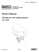
5. On models with skid plate, remove the skid plate
and cut the driver-side corner according to the photo
below. After cutting reattach the skid plate to the
vehicle.
CAUTION
Read instructions before assembling. Fasteners
should be finger tight until instructed to tighten
according to the torque chart. Use standard
methods and practices when attaching
snowplow including wearing proper personal
protective safety equipment.
2-1/2"
2-1/4"
Remove
and
discard.

Lit. No. 28047 5 November 1, 2003
3713
6. Place the mount against the front-end cross
member and align the front holes of the mount with
the holes in the bottom of the frame rails.
7. Place two 3/8-16 cap screws into a clamping plate
and insert into the end of the frame rail. Drop the
cap screws down through the holes in the frame
and the holes in the mount. Place a 3/8" locknut
onto each bolt, and hand tighten.
8. Insert a 3/8" flat washer through the square hole in
the front cross member and position it over the
round hole located just to the side of this. Bend a
3/8" bolt with handle as needed to insert it through
the square hole and hook it down through the 3/8"
flat washer, through the front cross member, and
through the slot in the plow mount. Place a 3/8" flat
washer and a 3/8" locknut on the bolt, and hand
tighten.
CAUTION
A washer must not be used at the drilled hole
nearest the outside of the truck due to an
interference with vehicle suspension
components.
Center the mount
about this bolt.
9. Repeat steps 7 and 8 on the opposite side of the
truck. Tighten all fasteners to be snug but allow
movement of the mount for positioning.
10. Verify that the vertical alignment of the rear of the
mount is roughly centered over the front-end
alignment bolt. Push the mount back until it is in
contact with the front-end cross member and clamp
the mount in place. This should allow for the offset
washer to rotate freely about the bolt once the
mount is installed.
11. Using the rear holes in the mount as guides, drill
four 13/32" holes through the front-end cross
member.
12. Place a 3/8" flat washer onto a 3/8" bolt with
handle, and insert the bolt into the front-end cross
member. Pass the bolt out through the drilled hole
nearest the center of the truck and the hole in the
rear of the mount. Place a 3/8" locknut on the bolt,
and hand tighten.
13. Insert another 3/8" bolt with handle into the front-
end cross member. Pass the bolt out through the
drilled hole nearest the outside of the truck and the
hole in the rear of the mount. Place a 3/8" locknut
on the bolt, and hand tighten.

November 1, 2003 6 Lit. No. 28047
3713
This hole is
at the center
of the air dam.
13-3/8"
9-3/8"
This mounting hole is
to be left intact on both
sides of the air dam.
This section on each
side has been removed
and discarded.
Note wire
location.
14. Repeat steps 12 and 13 on the opposite side of the
truck. Rotate the ends of the handles up until they
contact the frame prior to tightening.
15. Tighten all fasteners to proper torque listed in the
torque chart.
16. Bend or cut the ends of the bolt handles protruding
out of the front cross member for appearance.
17. Reinstall the two covers over the ends of the frame
rails.
18. It is suggested to run the wiring harness and cable
prior to proceeding with these instructions. Once
the wiring is in place leave the wires needed to
splice into the vehicle park/turn signal wiring
protruding out underneath the headlamps. These
can be connected once the bumper has been refit
to the vehicle.
19. Using the hole in the center of the air dam as a
guide, measure and cut two 4" wide pieces from the
air dam as dimensioned and shown below. These
dimensions are the same for the opposite side of
the air dam. The two mounting holes are to be left
intact as noted.

Lit. No. 28047 7 November 1, 2003
3713
Marson is a brand owned by ALCOA
This hole is at the
center of the bumper.
12-1/4" 5/8" wide
slot in 4
places
9-3/8"
5-1/2"
inside
slots
5-3/4"
outside
slots
This mounting hole is
to be left intact on both
sides of the bumper.
Plastic
Rivets
20. Using the hole in the center of the bumper as a
guide, cut four slots in the bottom of the bumper to
the dimensions shown below. These dimensions are
the same for the opposite side of the bumper. The
outer slots need to be 1/4" longer than the inner
slots as shown and the two mounting holes are to
be left intact as noted.
21. Reinstall the front bumper. The bumper wraps under
the cross tube of the mount, and the slots in the
bottom of the bumper fit around the side plates. The
center section of the air dam is mounted with the
bumper using the original fasteners.
NOTE: The plastic rivet manufacturer claims that
"Under extremely dry conditions these rivets may
break 'short' due to moisture loss. Should this
occur, soak the rivets in water overnight.
22. The end pieces of the air dam are fastened to both
the bumper and the plastic wheel-well using two
plastic rivets as shown. This procedure requires the
use of a Marson brand Klik-Loc™ plastic rivet setter
number 48000 or equivalent, which is available from
many local automotive centers or dealerships.

November 1, 2003 8 Lit. No. 28047
3713
The company reserves the right under its product improvement policy to change construction or design details and furnish equipment when so
altered without reference to illustrations or specifications used. Do not exceed vehicle ratings with a snowplow. The company offers a limited
warranty for all snowplows. See separately printed page for this important information.
Printed in USA
23. Reinstall the plastic rivets holding the fender flaring
to both the bumper and the plastic wheel well.
24. Complete the installation of the wiring by splicing
into the vehicle park/turn signal wiring per the
electrical system installation instructions.
NOTE: After five to ten hours of snowplow usage,
retorque all mount assembly fasteners.
/