Baumer OM70T-P0140.HH0130.VI Operating instructions
- Type
- Operating instructions

RS485 Protocol Structure

en_BA_RS485
_Protocol_Structure.docx
2/25
Baumer Electric AG
07.06.2017 14:07/tof V1.4 ANW_81149632
Frauenfeld, Switzerland
Contents
1
Introduction ................................................................................................................................... 3
1.1
The RS-485 Interface ..................................................................................................................... 3
1.2
Commissioning Procedure with RS485 .......................................................................................... 3
2
Connection .................................................................................................................................... 4
2.1
Sensor Connection Diagram ........................................................................................................... 4
3
Topology ........................................................................................................................................ 5
3.1
≤ 115 kbit/s: Topology for Baumer standard RS485 interfaces ....................................................... 5
3.2
≤ 3 Mbit/s: Topology for Baumer fast RS485 interfaces ................................................................. 7
3.3
Using other outputs in addition to RS485 ....................................................................................... 9
4
Commands .................................................................................................................................. 10
4.1
Command Structure ...................................................................................................................... 10
4.2
Time Flows (Timing)...................................................................................................................... 16
5
Error handling ............................................................................................................................. 20
5.1
General information ...................................................................................................................... 20
5.2
Application specific error 11 .......................................................................................................... 21
6
Appendix ...................................................................................................................................... 22
6.1
Data types ..................................................................................................................................... 22
6.2
Example Index Table..................................................................................................................... 23
7
History of changes ..................................................................................................................... 24

en_BA_RS485
_Protocol_Structure.docx
3/25
Baumer Electric AG
07.06.2017 14:07/tof V1.4 ANW_81149632
Frauenfeld, Switzerland
1 Introduction
1.1 The RS-485 Interface
Besides up to 31 sensors the bus contains a master which represents a PC or also a PLC (Programmable
Logic Controller). Communication with the desired sensor on the bus is initiated by the master, upon which the
sensor answers. Data can be sent by the master to the sensor (WRITE) or requested by it (READ). No data is
sent by the sensors without being requested by the master.
A message to the sensor contains:
• Sensor address
• Type: read or write
• Index: which command is to be executed
• Data (if required)
An answer from the sensor contains:
• Sensor address
• Type of answer (e.g. acknowledge, error, busy ....)
• Data (if required)
1.2 Commissioning Procedure with RS485
1 Connect the sensor according to the connection diagram, note recommended cables
2 Connect all the components to the required topology
3 Supply the sensor with +24 VDC
4 Enable the sensor for RS485 commands via the index command 010 "RS485 lock"
5 Control the sensor via the index commands with RS485

en_BA_RS485
_Protocol_Structure.docx
4/25
Baumer Electric AG
07.06.2017 14:07/tof V1.4 ANW_81149632
Frauenfeld, Switzerland
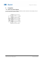
2 Connection
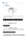
2.1 Sensor Connection Diagram
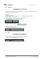
+Vs and 0V are used for the power supply and RS485 uses Rx/Tx+ and Rx/Tx- for data exchange. These 4
pins are required for the operation of RS485.
Example of an 8-pin connection diagram

en_BA_RS485
_Protocol_Structure.docx
5/25
Baumer Electric AG
07.06.2017 14:07/tof V1.4 ANW_81149632
Frauenfeld, Switzerland
3 Topology
There are two different recommended network structures depending on the sensors RS485 interface and the
needed data transfer rate.
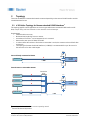
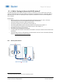
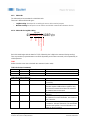
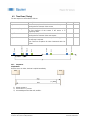
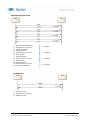
3.1 ≤ 115 kbit/s: Topology for Baumer standard RS485 interfaces
1
This topology applies to most applications and sensor types with Baumer standard RS485 interface ≤115
kbit/s. Simple wiring and lower demands on the materials are the advantages.
Requirements:
• Shielded cables necessary
• Maximum 10m length from sensor to master
• At maximum 15 sensors
2
can be integrated in such a network
• Data transfer rates up to 115 kbit/s for RS485
• In order to define the resistance level when no transmitter is active, the master must have failsafe bias
resistors R
B
• The topology for Baumer fast RS485 interfaces (≤ 3 Mbit/s) is recommended for up to 31 sensors in
the same bus or for other cable lengths
Sensor directly connected to Master
Several sensors connected to master
1
According to the data sheet in the sensors operating manual
2
Tested and released by Baumer
Vcc
Rx/Tx-
Rx/Tx+
RS485
Master
B
Sensor 1
C
Sensor
2
Sensor
3
Sensor
15
RS485
Master
A
< 10m
D
<
5
m
<
5
m
B
B
B
B
C
C
C
D
R
B
R
B
Vcc
R
B
R
B
Rx/Tx+
Rx/Tx-
Sensor 1
C
Connection
point

en_BA_RS485
_Protocol_Structure.docx
6/25
Baumer Electric AG
07.06.2017 14:07/tof V1.4 ANW_81149632
Frauenfeld, Switzerland
A
Cable <10m
Maximum 10m length from sensor to master
10155587 ESG 34CH1000G
(5-pin, length 10 m, straight connector)
11046266 ESG 34CH0500G
(5-pin, length 5 m, straight connector)
11046264 ESG 34CH0200G
(5-pin, length 2 m, straight connector)
10129333 ESG 34FH1000G
(8-pin, length 10 m, straight connector)
10129332 ESG 34FH0500G
(8-pin, length 5 m, straight connector)
10127844 ESG 34FH0200G
(8-pin, length 2 m, straight connector)
Other cable lengths available on request
C
Sensor
Sensor with Baumer standard RS485
interface. Data transfer rates up to 115
kbit/s.
B
Cable <5m
Maximum 5m length to the connection point
11046264 ESG 34CH0200G
(5-pin, length 2 m, straight connector)
10127844 ESG 34FH0200G
(8-pin, length 2 m, straight connector)
Other cable lengths available on request
D
RS485
Master
The PC/PLC (Programmable Logic
Controller) controls the devices as master.
The master must have two Failsafe bias
resistors R
B
(300 Ohm - 5 kOhm, Pull-Up for
Rx/Tx+ and Pull-Down for Rx/Tx- resistors).

en_BA_RS485
_Protocol_Structure.docx
7/25
Baumer Electric AG
07.06.2017 14:07/tof V1.4 ANW_81149632
Frauenfeld, Switzerland
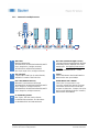
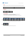
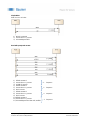
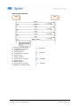
3.2 ≤ 3 Mbit/s: Topology for Baumer fast RS485 interfaces
3
The defined topology and also high performance cables are required for sensors with Baumer fast RS485
interfaces with data transfer rates up to 3Mbit/s. Each device is connected in series to a single bus cable, on
both sides of the bus cable is a terminating resistor required. At maximum 31 sensors can be integrated in
such a network
Requirements:
• Both ends of the bus cable must be terminated with terminating resistors R
T
, value = 120 Ohm
• The terminating resistor can be integrated in the master or in the sensor
• The wave resistance of the bus cable must be 120 Ohm
• The stub line length has to be shorter than 0.3m (length = A)
• The cable lengths between the Tee connectors have to be in minimum 1m (length = C)
• The required transfer rate define the total length of the bus cable (length = E)
• At maximum 31 sensors in the same bus
• The cables must be twisted pair and shielded
• In order to define the resistance level when no transmitter is active, the master must have failsafe bias
resistors R
B
• The total length of the bus cable depends on the data transfer rate and can be calculated by following
formula: 10^8 [bps*m]/ Data transfer rate [bps]
3.2.1 Point to point structure
3
According to the data sheet in the sensors operating manual
Rx/Tx+
Rx/Tx
-
Vcc
RS485
Master
R
B
R
B
Sensor
A
B
F
D1
R
T
R
T
Example with
i
ntegrated
terminating resistor
R
T
Example with
separated
terminating resistor
R
T
E
G
C

en_BA_RS485
_Protocol_Structure.docx
8/25
Baumer Electric AG
07.06.2017 14:07/tof V1.4 ANW_81149632
Frauenfeld, Switzerland
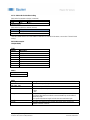
3.2.2 Structure for multiple sensors
A
Stub cable
Maximum length 0.3m
11144301 ESG 34C/KSG34CH0030G/C/OBEZ
(5-pin, length 0.3 m, straight connector)
11147130 ESG 34F/KSG34CH0030G/C
(8-to-5-pin, length 0.3 m, straight connector)
E
Bus cable
(maximum length over all)
The total maximum length between the both
terminating resistors depends on the data
transfer rate: 10^8 [bps*m]/ Data transfer
rate [bps]
Example: 10^8/3000000=33 --> 33m
B
Tee connector
T-junction M12 CAN 5-pin (1 male/2 female)
10153972 T-Verteiler 5Pol M12 CAN
F
Sensor
Sensor with Baumer fast RS485 interface.
Data transfer rates up to 3Mbit/s.
C
Bus c
able
(
between devices
)
Minimum 1m and maximum 5m length
11144304 ESG 34C/KSG34CH0200G/C/OBEZ
(5-pin, length 2 m, straight connector)
11144306 ESG 34C/KSG34CH0500G/C/OBEZ
(5-pin, length 5 m, straight connector)
G
RS485
Master
with
≤
3Mbit/s
The PC/PLC (Programmable Logic
Controller) controls the devices as master.
The master must have two Failsafe bias
resistors R
B
(600 Ohm - 5 kOhm, Pull-Up for
Rx/Tx+ and Pull-Down for Rx/Tx- resistors).
Data transfer rate ≤ 3Mbit/s.
D
1
D2
R
T
Terminating
resistor
M12, 5-pole, 120 Ohm, male or female
D1 10153974 Rundstecker 5Pol Abschluss-
D2 11163234 ESG 34C CAN-terminator
R
T
Rx/Tx+
Rx/Tx
-
Sensor 2
Sensor …
Sensor
31
A
A
A
C
B
B
B
Sensor 1
C
A
A
B
B
C
C
C
E
F
F
F
F
D1
D2
Vcc
RS485
Master
G
R
B
R
B
R
T

en_BA_RS485
_Protocol_Structure.docx
9/25
Baumer Electric AG
07.06.2017 14:07/tof V1.4 ANW_81149632
Frauenfeld, Switzerland
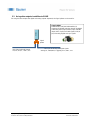
3.3 Using other outputs in addition to RS485
For using the other outputs like digital and analog outputs separated, the Signal splitter can be used for.
Signal
splitter
Sensor
M12 5-pin for RS485 signals
Rx/Tx+ ; Rx/Tx
-
; GND
;
+VS
M12 8-pin for Analog and Digital signals
Analog I/U ; PNP/NPN
;
Trigger/Sync In;
GND
;
+VS
8-pol
5-pol
8-pol
Signal splitter
11141539 ESG 34F/KSG34FU0005G/C/S
Separator for RS485 and other signals like Digital
and Analog. M12 (8-pin) to M12 (5-pin) and M12
(8-pin). M12 (5-pin) for RS485 signals, M12 (8-
pin) for Analog, Digital and sync signals.

en_BA_RS485
_Protocol_Structure.docx
10/25
Baumer Electric AG
07.06.2017 14:07/tof V1.4 ANW_81149632
Frauenfeld, Switzerland
4 Commands
4.1 Command Structure
:01W020;10;41BE\r\n
The information to be transmitted is called PAYLOAD and has to be sent in a so-called frame so that the
command can be recognized and processed.
This frame always has the same structure and contains a start, a device address, a PAYLOAD, a checksum
and an end.
START DEVICE ADDR PAYLOAD CHECKSUM END
1 char 2 char n char 4 char 2 char
: 01…31 Commands **** \r\n
4.1.1 START
:01W020;10;41BE\r\n
The beginning of the command is indicated by a colon : .
ASCII HEX
: 0x3A
4.1.2 DEVICE ADDR
:01W020;10;41BE\r\n
DEVICE ADDR stands for device address and corresponds to the address which is required to actuate the
correct sensor in a network with several sensors. The device address 01 … 31 can be programmed in the
sensor. Sensors in the same network must not have the same device address. The standard device address
is 01.
ASCII HEX
0…31 0x30 0x30…0x33 0x31
PAYLOAD
START
DEVICE ADDR
CHECKSUM
END
TYPE
INDEX
SEPARATOR
SEPARATOR
PAYLOAD ELEMENT

en_BA_RS485
_Protocol_Structure.docx
11/25
Baumer Electric AG
07.06.2017 14:07/tof V1.4 ANW_81149632
Frauenfeld, Switzerland
4.1.3 PAYLOAD
The information to be transmitted is called PAYLOAD.
There are 2 different PAYLOAD types:
• Legible Coding- Developed for controlling the sensor with a terminal program
• Machine Coding- Developed to ensure efficient and reliable communication between devices
4.1.3.1 PAYLOAD for Legible Coding
:01W020;10;41BE\r\n
Each PAYLOAD begins with the letter for TYPE, followed by the 3-digit index command (during sending).
Then any number of payload elements can follow (depending on the index command), each separated by so-
called separators.
TYPE
Defines how the sensor has to deal with the command (read or write).
TYPE List for Send Command
ASCII HEX MESSAGE Explanation
R 0x52 READ Read from the sensor. No PAYLOAD ELEMENT.
W 0x57 WRITE Write to the sensor. With PAYLOAD ELEMENT.
TYPE List for Sensor Answer
ASCII HEX MESSAGE Explanation
A 0x41 ACK The command was received and executed
successfully.
a 0x61 ACKBUSY The command was received successfully, but
execution requires additional time. Applies to very
time-intensive commands and does not mean that
the command was not executed.
B 0x42 BUSY The device is busy and could not receive the
command.
E 0x45 ERROR An error occurred during analysis or execution of
the command. For more information, see section on
Error Correction.
e 0x65 ERROR LASTCMD An error occurred during the last command (applies
to read/write - delayed commands). The transmitted
command was ignored. For more information, see
section on Error Correction.
PAYLOAD
TYPE
INDEX
SEPARATOR
SEPARATOR
PAYLOAD ELEMENT

en_BA_RS485
_Protocol_Structure.docx
12/25
Baumer Electric AG
07.06.2017 14:07/tof V1.4 ANW_81149632
Frauenfeld, Switzerland
INDEX
Consists of 3 characters and defines the command to be executed (See separate RS485 Index Command
List).
ASCII Hex
000 … 999
0x30 0x30 0x30 … 0x39 0x39 0x39
SEPARATOR
Separator to subdivide commands.
ASCII HEX MESSAGE
; 0x3B READ
PAYLOAD ELEMENT
The corresponding value is added depending on the INDEX command and the TYPE.
If TYPE = R (read), there is no need for a PAYLOAD ELEMENT.
If TYPE = W (write), a PAYLOAD ELEMENT is needed for transmitting the value to the sensor.
PAYLOAD for writing to device
TYPE INDEX SEPARATOR
PAYLOAD
ELEMENT
SEPARATOR
PAYLOAD
ELEMENT
SEPARATOR
…
1 char 3 char 1 char n char 1 char n char 1 char …
W 020 ; 10 ; …. ; …
Example:
:01W020;10;41BE\r\n (W=Write; 020= Measurement Type Selection;10 = AVG Distance)
PAYLOAD for reading from device
TYPE INDEX
1 char 3 char
R 020
Example:
:01R020;99F5\r\n (R=Read; 020= Measurement Type Selection)
Example
Example

en_BA_RS485
_Protocol_Structure.docx
13/25
Baumer Electric AG
07.06.2017 14:07/tof V1.4 ANW_81149632
Frauenfeld, Switzerland
4.1.3.2 PAYLOAD for Machine Coding
PAYLOAD from master to device (command)
TYPE INDEX DATA
uint8 uint8 uint8 [ ]
7-bit ASCII bin*
PAYLOAD from device to master (answer)
TYPE PAYLOAD
uint8 uint8 [ ]
7-bit ASCII bin*
*The PAYLOAD consists of TYPE + INDEX + DATA as a 7-bit ASCII bit stream, see section "7-bit ASCII bin
coding"
PAYLOAD example:
12Aq34oit&/&()
TYPE
VALUE MESSAGE
0 Reserved
1 READ
2 WRITE
3 ACK
4 ACKBUSY
5 BUSY
6 ERROR
7 ERROR LASTCMD
INDEX
VALUE
0…255
DATA
Data type
Coding
uint8, uint16, uint32,
int8, int16, int32
Little endian integer (low byte first)
float32 32 bit according to IEEE754
bool Coded as uint8, whereby:
0: false
1: true
string Zero terminated string with a defined maximum length.
The field is filled with zeros after the zero termination up to the defined
maximum length.
The specified maximum length includes the zero termination byte.
fixlist[] All entries are linked.
varlist[] All entries are linked and pre-pended with uint32 which contains the
number of entries in the list.

en_BA_RS485
_Protocol_Structure.docx
14/25
Baumer Electric AG
07.06.2017 14:07/tof V1.4 ANW_81149632
Frauenfeld, Switzerland
7-bit ASCII bin coding
Ciphering method
• The binary data is divided into 7-bit groups
• The last 7-bit groups are filled with 0 bits
Extend each group with a most significant bit of 1 to 8 bits
Example:
Raw data: 0x33 0x33 0x33
Transmission data: 0x99 0xCC 0xE6 0xB0
BYTE 0 0x33
0
0
1
1
0
0
1
1
0
0
1
1
0
0
1
1
0
0
1
1
0
0
1
1
0
0
1
1
0
0
1
1
0
0
1
1
0
0
1
1
0
0
1
1
0
0
1
1
0
0
0
0
1
0
0
1
1
0
0
1
1
1
0
0
1
1
0
0
1
1
1
0
0
1
1
0
1
0
1
1
0
0
0
0
0
0
0
0
1
1
1
1
BYTE 1 0x33
BYTE 2 0x33
0x99
0xCC
0xE6
0xB0

en_BA_RS485
_Protocol_Structure.docx
15/25
Baumer Electric AG
07.06.2017 14:07/tof V1.4 ANW_81149632
Frauenfeld, Switzerland
4.1.4 CHECKSUM
:01W020;10;41BE\r\n
The CHECKSUM is used to check for correct transmission. It consists of the START, DEVICE ADDR and
PAYLOAD values and always has 4 digits.
Calculation:
CRC16-ARC / CRC-IBM
Bit-reflected polynom : x^16 + x^15 + x^2 + 1 = 0x8005, bit-reflected = 0xA001.
Init value : 0x0000, no final XOR value.
See http://reveng.sourceforge.net/crc-catalogue/16.htm for details.
Calculation example:
START :
DEVICE ADDR 01
PAYLOAD W020;10;
Accordingly, the checksum consists of:
:01W020;10; = 41BE
Wildcard character for checksum:
A wildcard character can also be used as CHECKSUM.
ASCII HEX
**** 0x2A0x2A0x2A0x2A
4.1.5 END
:01W020;10;41BE\r\n
The end of the frame or command is marked by the 4-digit combination \r\n.
Important: This command must always be sent as HEX.
ASCII HEX
\r\n
0x0D 0x0A

en_BA_RS485
_Protocol_Structure.docx
16/25
Baumer Electric AG
07.06.2017 14:07/tof V1.4 ANW_81149632
Frauenfeld, Switzerland
4.2 Time Flows (Timing)
The time sequences are defined as follows:
Name Description Min Max
t_answer
Time from reception of the last character of request to
sending the first character of the answer.
2.5 ms
t_answer_diagmode
Time from reception of last character of request to sending
the first character of the answer if the sensor is in
diagnosing mode.
200 ms
t_idle
Time from reception of the last character of answer to
sending the first character of the next request.
0.1 ms
t_break
If a request or an answer is not completed during t_break,
the message is rejected.
Note: There are exceptions for index Commands with a lot
of data.
500 ms
4.2.1 Sequences
Simple Read
Read access to an index, the data is replied immediately.
1) READ command
2) Answer time <= t_answer
3) Acknowledgment and data ACK,<DATA>
t
t_break
t_idle
Request
ACKBUSY
t_answer
Request
BUSY
Request
BUSY
Request
BUSY/ ACK

en_BA_RS485
_Protocol_Structure.docx
17/25
Baumer Electric AG
07.06.2017 14:07/tof V1.4 ANW_81149632
Frauenfeld, Switzerland
Simple Write
Write access to an index.
1) WRITE command
2) Answer time <= t_answer
3) Acknowledgment ACK
Read with postponed answer
1) READ command
2) Answer time <= t_answer
3) ACKBUSY answer
4) READ command
5) Answer time <= t_answer
6) BUSY answer
7) READ command
8) Answer time <= t_answer
9) BUSY answer
10) READ command
11) Answer time <= t_answer
12) Acknowledgment and data ACK,<DATA>
1. Sequence
2. Sequence
3.
Sequence
4. Sequence

en_BA_RS485
_Protocol_Structure.docx
18/25
Baumer Electric AG
07.06.2017 14:07/tof V1.4 ANW_81149632
Frauenfeld, Switzerland
Write with postponed answer
1) WRITE command,<DATA>
2) Answer time <= t_answer
3) ACKBUSY answer
4) READ command
5) Answer time <= t_answer
6) BUSY answer
7) READ command
8) Answer time <= t_answer
9) BUSY answer
10) READ command
11) Answer time <= t_answer
12) ACK acknowledgment
Read with error
1) READ command
2) Answer time <= t_answer
3) ERROR answer
1. Sequence
2. Sequence
3. Sequence
4. Sequence

en_BA_RS485
_Protocol_Structure.docx
19/25
Baumer Electric AG
07.06.2017 14:07/tof V1.4 ANW_81149632
Frauenfeld, Switzerland
Write Postponed with error
1) WRITE command,<DATA>
2) Answer time <= t_answer
3) ACKBUSY answer
4) READ command
5) Answer time <= t_answer
6) BUSY answer
7) READ command
8) Answer time <= t_answer
9) BUSY answer
10) READ command
11) Answer time <= t_answer
12) ERROR_LASTCMD answer
2. Sequence
3. Sequence
4. Sequence
1. Sequence

en_BA_RS485
_Protocol_Structure.docx
20/25
Baumer Electric AG
07.06.2017 14:07/tof V1.4 ANW_81149632
Frauenfeld, Switzerland
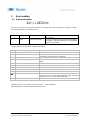
5 Error handling
5.1 General information
:01E;11;2E72\r\n
If an error occurs, the sensor answers with an E or e in the payload. The E is written as an uppor or a lower
case letter depending on what the error was.
E 0x45 ERROR An error occurred during analysis or execution of
the command.
e 0x65 ERROR LASTCMD An error occurred during the last command (applies
to read/write - delayed commands). The transmitted
command was ignored.
The error type is also sent with a number in the payload.
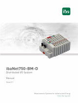
1 Wrong message type Only Read or Write are valid for requests from master to device.
2 Wrong payload format For example a missing separator
3 Wrong argument The given argument type doesn't match the expected type (ex.
Float value if an integer value is expected).
4 Wrong argument count Number of arguments mismatch.
5 Not enough data The length of the payload is below its minimum (type and
index).
6 Index do not exist
7 Index locked
8 Access not allowed Ex. Write access to read only index.
9 Not enough memory for encoding Internal error.
10 Not possible to encode argument Internal error.
11 Application specific error Not RS485 stack related error, read out chapter “Application
specific error 11” and the sensor-belonging Index Command
000 “Application error” for detailed information.
12 Wrong state Internal error.
Sample answer of a sensor when an error occurred: :01e;11;2E72\r\n
Error during the last command: Application specific error
Page is loading ...
Page is loading ...
Page is loading ...
Page is loading ...
Page is loading ...
-
 1
1
-
 2
2
-
 3
3
-
 4
4
-
 5
5
-
 6
6
-
 7
7
-
 8
8
-
 9
9
-
 10
10
-
 11
11
-
 12
12
-
 13
13
-
 14
14
-
 15
15
-
 16
16
-
 17
17
-
 18
18
-
 19
19
-
 20
20
-
 21
21
-
 22
22
-
 23
23
-
 24
24
-
 25
25


Baumer OM70T-P0140.HH0130.VI Operating instructions
- Type
- Operating instructions
Ask a question and I''ll find the answer in the document
Finding information in a document is now easier with AI
Related papers
-
Baumer OXH7-Z0500.HI0660.VI Operating instructions
-
Baumer OM70-L0250.HH0240.VI Operating instructions
-
-
-
-
Baumer LBFH Operating instructions
-
-
-
Baumer PF20S Operating instructions
-
Baumer PFMH User guide
Other documents
-
 EnGenius Technologies ESG-8808R User manual
-
Block ESG 7 User manual
-
 Badger Meter ModMAG M1000 User manual
-
Johnson Controls OpenBlue Industrial Refrigeration Gateway Installation guide
-
Agilent Technologies Stereo System E4400-90335 User manual
-
 Co2meter LOX-02 UV Flux 25% Oxygen Smart Sensor User manual
-
 IBA ibaNet750-BM-D Owner's manual


