Page is loading ...

INSTALLATION &
OPERATION MANUAL
IPSi3000MW/Y Series
PURE-SINE INVERTER
8128 River Way, Delta B.C. V4G 1K5 Canada T. 604.946.9981 F. 604.946.9983 TF. 800.668.3884 (US/CANADA)
www.analyticsystems.com
An ISO9001 Registered Company Battery Chargers • Inverters • Power Supplies • Voltage Converters

2
1. SAVE THESE INSTRUCTIONS — This manual contains important safety and operating
instructions for the Inverter.
2. Do not expose the Inverter to rain or snow.
3. Use of an attachment not recommended or sold by the Inverter manufacturer may result
in a risk of re, electric shock, or injury to persons.
4. Do not disassemble the Inverter; take it to a qualied serviceman when service or repair
is required. Incorrect reassembly may result in a risk of electric shock or re.
5. To reduce risk of electric shock, disconnect the Inverter from the input power before at-
tempting any maintenance or cleaning. Turning off controls will not reduce this risk.
6. Never place the Inverter directly above a battery; gases from the battery will corrode and
damage the Inverter.
7. Never allow battery acid to drip onto the Inverter.
HEAVY DEVICE - The IPSi2000MW and IPSi3000MW Inverters weigh more than 70 pounds
and 90 pounds respectively. Please use appropriate safety measures when lifting or moving
these units.
Medical Equipment Notice
Analytic Systems does not recommend the use of their products in life support
applications where failure or malfunction of this product can be reasonably
expected to cause failure of the life support device or to signicantly affect its
safety or effectiveness. Analytic Systems does not recommend the use of any
of its products in direct patient care. Examples of devices considered to be life
support devices are neonatal oxygen analyzers, nerve stimulators (whether used
for anesthesia, pain relief, or other purposes), auto-transfusion devices, blood
pumps, debrillators, arrhythmia detectors and alarms, pacemakers, hemodialysis
systems, peritoneal dialysis systems, neonatal ventilator incubators, ventilators
for both adults and infants, anesthesia ventilators, and infusion pumps as well as
any other devices designated as “critical” by the U.S. FDA
GROUNDING AND AC POWER CORD CONNECTION INSTRUCTIONS — Inverters
should be grounded to reduce risk of electric shock. This Inverter is equipped with a
chassis grounding stud, and electric receptacles capable of accepting an equipment-
grounding conductor and a grounding plug.
INVERTER
IMPORTANT SAFETY INSTRUCTIONS

3
TABLE OF CONTENTS
• Front Cover, Product Photo and Title
• Product Warnings and Advisories
• Table of Contents
• Description/Overview of Product
• Main Parts
• Operation Instructions
• Mounting Instructions
• Connection Instructions
• Conguration Instructions
• Options
• Faults
• Specications
• Warranty
Revised - September 8, 2017
Copyright Analytic Systems Ware (1993) Ltd.

4
The IPSi3000MW series of Intelligent Pure Sinewave Inverters are designed specically for
running computers and other sensitive AC loads in rugged, mobile, and off-grid environments.
They produce pure sine wave AC power, identical to a regular AC outlet.
This innovative design uses a pair of IP68 rated fans to cool the exterior of the enclosure,
allowing full power operation of the Inverter while maintaining water and dust resistance. The
IPSi3000MW model is built to be water resistant to the IP66 specication and the IPSi3000MY
model is individually tested and certied waterproof to the IP67 specication.
Standardized high current MIL connectors provide a solid connection to the battery and to
the AC loads, allowing easy interchange between 1000, 2000, and 3000 watt models without
rewiring.
The IPSi3000MW series Inverter is controlled by a sophisticated Digital Signal Processor (DSP)
for optimal control and the most efcient operation possible. The heavy duty Toroidal Power
Transformer steps the low voltage AC produced by the Power MOSFET Transistors from 110 to
220 VAC at 50 Hz as well as lters the AC output to reduce or eliminate electrical noise that
can interfere with sensitive communications equipment.
Using the free to download Inverter Wizard software, the user can select output frequency,
output voltage and low voltage shutdown parameters from any PC through a standard USB
interface.
FEATURES
• Fully regulated Pure Sine Wave output at 110 VAC / 60 Hz or 220 VAC / 50 or 60 Hz,
identical to commercial AC.
• Digitally controlled for precision frequency (± 0.01 Hz) at 50 or 60 Hz.
• State-of-the-art MOSFET technology and sophisticated DSP control for efcient and
reliable operation.
• AC powered output light for positive indication of proper operation.
• Transformer type output to protect computers and other sensitive equipment from
surges and spikes.
• Low voltage warning and shutdown circuitry to protect the batteries.
• Over voltage, over temperature warning and shutdown circuitry to protect the Inverter.
• Short circuit protection.
• LED indicators and a buzzer to bring attention to alarms and faults.
Introduction

5
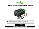
1. Indicator LEDs
2. IP68 rated Remote Port (Optional)
3. DC Negative In (Female)
4. DC Positive In (Male)
5. Chassis Ground Stud
6. IP68 rated microUSB Port
7. AC Output On Indicator
8. On/Off Switch
9. AC Input Connector (Optional)
10. AC Output Connector and Fuse
Main Parts
1
Rear Panel
2
3
7
1
4
8
9
10
2
6
5
The box you have received should contain the following:
• One IPSi3000MW Inverter
• One MicroUSB to PC cable
• This User Guide (A PDF copy can be downloaded from www.analyticsystems.com)
• One Warranty Card
• Inverter Wizard software can be downloaded from www.analyticsystems.com
If anything is missing or damaged please contact your dealer or Analytic Systems for a replacement.
Box Contents
Front Panel
1. Waterproof Cooling Fans (x2) 2. Lifting Handles (x2)

6
Operation
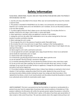
Controls and Indicators
Move the On/Off switch to the ON position to energize the circuitry. The AC Output LED and
Invert LED will glow green to indicate the presence of AC power at the output terminal. Either
the 50Hz or 60 Hz LED will glow green corresponding to the Inverter’s output frequency.
The IPSi3000MW Inverter features On/Off power switch, a
microUSB port and 8 LED indicators. Their functions are detailed
below.
1. Low Voltage:
• Blinks red when the input voltage is near the lower limit for
proper operation. Glows red when the input voltage is too low for proper operation. The
Bypass LED will also glow red and the AC Output Power LED will turn off.
• Check the rating of the input voltage. Make sure the Low Input threshold is set properly
for the battery voltage you are using, ~21V for a 24V battery, ~28V for a 32V battery and
~31V for a 36V battery.
2. High Voltage:
• Blinks red when the input voltage is near the upper limit for proper operation. Glows
red when the input voltage is too high for proper operation. The Bypass LED will also
glow red and the Invert LED will turn off.
• Check the rating of the input voltage. The Inverter can be damaged if the input voltage
exceeds the maximum rating. Over-voltage damage is not covered under warranty.
3. Over Temp:
• Blinks red if the internal temperature of the Inverter is approaching the safe limit. The
Inverter will reduce its maximum power rating to try to maintain a safe operating tem-
perature. The LED will glow red if the Inverter becomes too hot to operate. The Bypass
LED will also glow red and the AC Output Power LED will turn off.
• Check that the cooling fans are not defective. If the fans are running, remount the
Inverter for better ventilation. If the fan is NOT running, the Inverter must be returned
for repair.
4. Over Load:
• Blinks red if the output amps drawn on the Inverter reaches the continuous rating.
Glows red if the amps drawn on the inverter reaches the maximum rating.
• Reduce the load connected to the Inverter.

7
Installation
Mounting
Mount the unit in a WELL VENTILATED area. Allow
at least one inch of clearance all around the unit
for adequate cooling. W series Inverters can be
exposed to water spray from any direction. Y series
Inverters can be exposed to water immersion up to
1 meter for a maximum of 30 minutes.
CAUTION: Do not mount the unit anywhere
explosive gases may accumulate. A slight arc may
occur when the power leads are connected, and
in the unlikely event of a failure, sparks may be
generated inside the unit.
Grounding
The case of the Inverter is connected to AC Ground and
AC Neutral to meet regulatory requirements and to
reduce the possibility of it generating any radio frequency
interference. The case must be bonded appropriately to the
grounding system of the vehicle or marine vessel.
On a vehicle, bond the Inverter case to the vehicle’s frame. On a marine vessel, bond the case
to the vessel’s hull. A grounding stud is provided on the front panel for this purpose. To ensure
proper grounding, check the connection with an ohmmeter. The case is isolated from the DC
input, so the DC power can be on a different ground from the AC output.
Disconnecting
If you need to disconnect the Inverter for service or storage, move the power switch to the OFF
position and disconnect the DC input. Then while it is disconnected, move the power switch
to the ON position turn and leave it in that position least one minute to discharge the storage
capacitors. Return the switch to the OFF position.
5. 50 Hz: This LED glows green if the Inverter is set for 50 Hz operation.
6. 60 Hz: This LED glows green if the Inverter is set for 60 Hz operation.
7. Bypass: This LED glows green if the Inverter is in Bypass mode. In this mode, the In-
verter acts as a backup power source when connected to external AC Power. This is only
available on units with the Off-Line UPS option. It glows red if the Inverter is in an Alarm
condition as described above.
8. Invert: This LED glows green when the Inverter is in normal operation.

8
Input Connections
Output Connections
DC Input Power Connection
Prepare a circuit breaker or fuse protected power source for the IPSi3000MW Series Inverter,
making sure the power switch is switched OFF. Connect the input power to the DC Input
terminals using the appropriate sized wire for the maximum input current, terminated
in connectors compatible with the GTC02R20-2P and GTC02R20-2S-RDS MIL connectors
provided. On the Inverter, the Positive connection is Male and the Negative connection is
Female.
The recommended mating connectors are GTC06F20-2S for the Positive connection and
GTC06F20-2P for the Negative connection. For IPSi Inverters of 3000 watts and higher, the
female connector must be RadSok (add -RDS to the part number) to handle the input current.
RECOMMENDATION: The biggest effect on Inverter performance and EMI is the length and
gauge of the DC Input connections. These should be the largest practical gauge of welding
wire that will t the input connectors (AWG 1/0 recommended) and as short as possible.
CAUTION: Do not reverse connect the input wires.
This will cause serious damage to the Inverter and will not be covered under warranty.
AC Input Power Connection (Optional)
If the Inverter is equipped with the Off-Line UPS option, there will also be one GTC02R-20-19P
connection for the AC input provided on the front panel. Connect a source of AC power to this
connection using the appropriate sized wire and a matching cable connector.
AC Output Power Connection
One GTC02R-20-19S output connection is provided. Connect to the loads with the matching
cable connector. Remember, AC Output connections are always Female. AC Input connections
are always Male.
CAUTION: Do not apply AC voltage to the output connection.
This will cause damage to the Inverter and will not be covered under warranty.
AC Output and Input Wiring Pinout
The wiring pinout is the same for both the AC Input and AC Output:
Pin A - AC Hot
Pin B - AC Neutral
Pin C - AC Ground (Chassis)

9
Remote Port (Optional)
This port is intended for use with an Analytic Systems Digital Remote Control, but it can also
be used for Remote On/Off, Isolated RS232 Communications and Dry Contact Output Fail. It
uses a standard RJ45 style connector with proprietary connections. Do not connect this port
to a computer. The wire colors described correspond to colors found in any standard T-568B
network cable.
Remote On/Off
Pins 1 (White/Orange) and 2 (Orange) are used to turn the Inverter ON or OFF. Connect them
together through a switch or relay to turn the Inverter OFF and disconnect them to turn the
Inverter ON. The main power switch must be ON for this connection to function.
Isolated RS232 Communications
Pins 4 (Blue), 5 (White/Blue) and 6 (Green) are an isolated RS232 port that can be used for
communication to/from the Inverter. Information on the standard data structure or custom
programming is available from the factory. Pin 4 is RX, Pin 5 is TX and Pin 6 is Return.
Dry Contact Output Fail Relay
Pins 7 and 8 (White/Brown and Brown) connect to the contacts of an Output Fail relay
controlled by the processor. The contacts will be CLOSED if the Inverter is operating normally
and OPEN if the Inverter has failed.
Ofine UPS (Optional)
The Off-Line UPS Option allows the Inverter to be connected an external AC power source
through AC Input Power Connection and serve as a backup power source. In the event that
the external AC power fails, the Inverter will power up and take over supplying AC power the
load, until either time the external AC power is restored or batteries for the Inverter becomes
discharged. While the load is connected external AC power, the Inverter will be in Bypass
mode and the Bypass LED will glow green.
The external AC voltage thresholds for the Inverter to take over supplying AC Power or to stop
supplying AC power are all factory preset to typical values. However using the Inverter Wizard
software you can adjust these values to t your specic needs.
Tip: Size the batteries to ensure proper operation of the Inverter for required amount of time
in event of external AC failure. For example, a 3000W Inverter running from 24 VDC will draw
~140 amps, so for 2 hours of runtime 280 amps hours of capacity at 24 volts is the minimum
required battery capacity.

10
Inverter Wizard Program
The Inverter is delivered preset for the input voltage, output voltage and frequency shown on
the label. If these parameters are satisfactory, the Inverter can be put directly into service.
The normal shutdown parameters are set for the lowest battery voltage the Inverter will
support are: 12 Volts for a -12 model, 24 Volts for a -20 model and 48 Volts for a -40 model.
If the Inverter is powered by alternate voltage such as 32 or 36 volts for a -20 model or 72 volt
rail (64 volt nominal) for a -40 model, then the low voltage shutdown parameters will need to
be adjusted. You can do so using the free to download Inverter Wizard software from www.
analyticsystems.com
Connect the Inverter to your PC using the microUSB interface on the front panel. From Inverter
Wizard, you can:
• Adjust the low voltage shutdown parameters (to match battery voltage)
• Adjust the Output Frequency (50 or 60 Hz)
• Adjust the Output Voltage (+/- 10 percent range at 1 VAC intervals)
• Update the Inverter’s rmware
• Graph Input Voltage, Input Current, Output Voltage and Output Current data.
Special Services & Options
View/download an expanded description of our Special Services & Options online
https://www.analyticsystems.com/download
A Line AC Detect & Autoswitch UPS
C
COTS
|
MIL461F, MIL810G (MIL Connectors) (Vibration Protection) (Wide temP {-40 to +55
o
c})
(in-house tested and rePort for each unit- aVailable as add on to m oPtion)
E European ROHS compliant (lead free manufactured)
I MIL461F (in-house tested and rePort for each unit- aVailable as add-on to m oPtion)
J MIL810G (in-house tested and rePort for each unit- aVailable as add-on to m oPtion)
M Military Rugged Package (MIL Connectors) (Vibration Protection) (Wide temP {-40 to +55
o
c})
U Safety Special Inspection (csa/ul)
X Heavy Duty Ruggedization (Vibration Protection) (Wide temP {-40 to +55
o
c})
Z No Conformal Coating

11
This page has been intentionally left blank.

12
This page has been intentionally left blank.

13
This page has been intentionally left blank.

14
Specications
* Specications subjects to change without notice.
Input Voltages -20 -40
Nominal (Vdc) 24, 28, 32 or 36 48 or 72 (Rail)
Actual (Vdc) 20 - 45 40 - 80
Input Amps (max) 200 100
Input Fuse (External, not supplied) 250 125
Output Voltages
Voltage -110 +/- 2 Vac -220 +/- 4 Vac
Output Amps (max) 25A (cont) / 30A (peak) 12.5A (cont) / 15A (peak)
Output Fuse 40 Amp 20 Amp
Output Frequency 50.00 or 60.00 Hz ± 0.01 Hz (user selectable)
Output Distortion <2% at 3000 Watts into resistive load
Regulation (Line & Load) < +/- 2.0%
Duty Cycle Continuous 100% for 24 hours per day
General
Efciency > 90% @ maximum output
Temp Range -40 to +55 deg C @ maximum output
Isolation Input-Output, Input-Case & Output-Case 1500Vdc Input
EMC Tested to meet MIL461F (expect for conducted noise on DC In)
Shock and Vibration Designed to meet MIL810G
Length 17.9 in / 45.5 cm
Width 14.1 in / 35.8 cm (including lifting handles)
Height 8.4 in / 21.3 cm
Clearance 1 Inch (2.5 cm) all around
Material Marine Grade Aluminum
Finish Black Anodize
Fastenings 18-8 Stainless Steel
Weight 88.5 lbs / 40.2 kg
Connections
Positive In – GTC02R20-2P c/w cover
Negative In – GTC02R20-2S-RDS c/w cover
AC Output Connection - GTC02R-20-19S c/w cover
AC Input Connection - GTC02R-20-19P c/w cover (with Off-Line UPS Option)
Warranty 2 Years

Limited Warranty
1. The equipment manufactured by Analytic Systems Ware (1993) Ltd. (the “Warrantor”) is warranted to be free
from defects in workmanship and materials under normal use and service.
2. This warranty is in effect for 2 years from the date of purchase by the end user.
3. Analytic Systems will determine eligibility for warranty from the date of purchase shown on the warranty card
when returned within 30 days, or
a. The date of shipment by Analytic Systems, or
b. The date of manufacture coded in the serial number, or
c. From a copy of the original purchase receipt showing the date of purchase by the user.
4. In case any part of the equipment proves to be defective, the Purchaser should do the following:
a. Prepare a written statement of the nature of the defect to the best of the Purchasers knowledge, and
include the date of purchase, the place of purchase, and the Purchasers name, address and telephone
number.
b. Call Analytic Systems at 800-668-3884 or 604-946-9981 and request a return material authorization
number (RMA).
c. Return the defective part or unit along with the statement at the Purchasers expense to the Warrantor;
Analytic Systems Ware (1993) Ltd., 8128 River Way, Delta, B.C., V4G 1K5, Canada.
5. If upon the Warrantor’s examination the defect proves to be the result of defective material or workmanship,
the equipment will be repaired or replaced at the Warrantor’s option without charge, and returned to the
Purchaser at the Warrantor’s expense by the most economical means. Requests for a different method of return
or special handling will incur additional charges and are the responsibility of the Purchaser.
6. Analytic Systems reserves the right to void the warranty if:
a. Labels, identication marks or serial numbers are removed or altered in any way.
b. Our invoice is unpaid.
c. The defect is the result of misuse, neglect, improper installation, environmental conditions, non-authorized
repair, alteration or accident.
7. No refund of the purchase price will be granted to the Purchaser, unless the Warrantor is unable to remedy the
defect after having a reasonable number of opportunities to do so.
8. Only the Warrantor shall perform warranty service. Any attempt to remedy the defect by anyone else shall
render this warranty void.
9. There shall be no warranty for defects or damages caused by faulty installation or hook-up, abuse or misuse of
the equipment including exposure to excessive heat, salt or fresh water spray, or water immersion except for
equipment specically stated to be waterproof.
10. No other express warranty is hereby given and there are no warranties that extend beyond those described
herein. This warranty is expressly in lieu of any other expressed or implied warranties, including any implied
warranty of merchantability, tness for the ordinary purposes for which such goods are used, or tness for a
particular purpose, or any other obligations on the part of the Warrantor or its employees and representatives.
11. There shall be no responsibility or liability whatsoever on the part of the Warrantor or its employees and rep-
resentatives for injury to any person or persons, or damage to property, or loss of income or prot, or any other
consequential or resulting damage which may be claimed to have been incurred through the use or sale of the
equipment, including any possible failure of malfunction of the equipment, or part thereof.
12. The Warrantor assumes no liability for incidental or consequential damages of any kind.

Register Products Online | www.analyticsystems.com/support/warranty-registration
DESIGNED AND MANUFACTURED BY
800-668-3884
604-946-9983
www.AnalyticSystems.com
8128 River Way
Delta, BC V4G 1K5 | Canada
Battery Chargers • Inverters • Power Supplies • Voltage Converters
/