ZIEHL TR600 analog Operating instructions
- Type
- Operating instructions
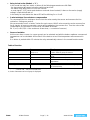
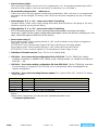
ZIEHL TR600 analog temperature controller and monitor can monitor up to 6 different measuring points simultaneously, making it ideal for temperature monitoring in motors, generators, transformers, and other power machines and plants. It has 6 sensor inputs with 2- or 3-wire connection, and 7 relay outputs with change-over contact. The 2 analog outputs, 0/4...20 mA and 0/2...10 V, can be used for remote displays or further evaluation. The TR600 analog also has a sensor error relay that monitors sensor break or sensor short circuit.
ZIEHL TR600 analog temperature controller and monitor can monitor up to 6 different measuring points simultaneously, making it ideal for temperature monitoring in motors, generators, transformers, and other power machines and plants. It has 6 sensor inputs with 2- or 3-wire connection, and 7 relay outputs with change-over contact. The 2 analog outputs, 0/4...20 mA and 0/2...10 V, can be used for remote displays or further evaluation. The TR600 analog also has a sensor error relay that monitors sensor break or sensor short circuit.


-
 1
1
-
 2
2
-
 3
3
-
 4
4
-
 5
5
-
 6
6
-
 7
7
-
 8
8
-
 9
9
-
 10
10
-
 11
11
-
 12
12


ZIEHL TR600 analog Operating instructions
- Type
- Operating instructions
ZIEHL TR600 analog temperature controller and monitor can monitor up to 6 different measuring points simultaneously, making it ideal for temperature monitoring in motors, generators, transformers, and other power machines and plants. It has 6 sensor inputs with 2- or 3-wire connection, and 7 relay outputs with change-over contact. The 2 analog outputs, 0/4...20 mA and 0/2...10 V, can be used for remote displays or further evaluation. The TR600 analog also has a sensor error relay that monitors sensor break or sensor short circuit.
Ask a question and I''ll find the answer in the document
Finding information in a document is now easier with AI
Related papers
-
ZIEHL TR400 Operating instructions
-
-
-
-
-
-
-
-
-
Other documents
-
Sony CCD-TR100 User manual
-
JL Audio TR600-CXi User manual
-
CPS Pro-Set TR600 Series Owner's manual
-
 Trimaco 12361/4HD Specification
-
Jensen MCR23017 User manual
-
Navman 6500 User manual
-
Victron energy Ziehl Voltage and frequency relay UFR1001E Owner's manual
-
True Fitness 600U User manual
-
Olympus C-2000 User manual
-
Sharp GB201 User manual
