KitchenAid KHMS155LBL3 Installation guide
- Type
- Installation guide

MICROWAVE HOOD COMBINATION
INSTALLATION INSTRUCTIONS
This product is suitable for use above electric or gas cooking products up to 36" (91.4 cm) wide.
These installation instructions cover different models. The appearance of your particular model may differ slightly from the
illustration in these installation instructions.
COMBINAClON MICROONDAS CAMPANA
INSTRUCClONES DE INSTALAClON
Este producto puede usarse encima de productos para cocci6n el6ctricos o a gas de 36" (91,4 cm) de ancho o menor.
Estas instrucciones de instalaci6n cubren diferentes modelos. La apariecia de su modelo en particular puede ser
ligeramente diferente de la ilustraci6n en estas instrucciones de instalaci6n.
Table of Contents / [ndice
MICROWAVE OVEN SAFETY ................................................... 2 SEGURIDAD DE LA COMBINACION MICROONDAS CAMPANA...
VENTING DESIGN SPECIFICATIONS ...................................... 2
INSTALLATION REQUIREMENTS ........................................... 3
Tools and Parts ....................................................................... 3
Location Requirements ........................................................... 4
Product Dimensions ............................................................... 4
Electrical Requirements .......................................................... 5
INSTALLATION INSTRUCTIONS ............................................. 5
Remove Mounting Plate ......................................................... 5
Rotate Air Deflector ................................................................. 5
Locate Wall Stud(s) ................................................................. 7
Mark Rear Wall........................................................................ 8
Drill Holes in Rear Wall............................................................ 8
Attach Mounting Plate to Wall ................................................ 9
Prepare Upper Cabinet ........................................................... 9
Install Damper Assembly ...................................................... 10
Installthe Microwave Oven .................................................. 10
Complete Installation ............................................................ t 2
ASSISTANCE ........................................................................... 12
Replacement Par_s ............................................................... t 2
Accessories ........................................................................... 12
13
ESPECIFICACIONES PARA EL DISEI(IO DE LAVENTILACION ...... 13
REQUISITES DE INSTALACION ......................................................... 15
Piezas y herrarnientas ........................................................................ 15
Requisites de ubicacion .................................................................... 15
Dimensiones del producto ................................................................ 16
Requisites el_ctricos .......................................................................... t 6
INSTRUCCIONES DE INSTALACION ................................................. 17
Retire la placa de montaje ................................................................. 17
Rote el desviador de aire ................................................................... 17
Ubique el(los) pie(s) derecho(s) de pared .......................................... 19
Marque la pared posterior ................................................................. 20
Taladrar orificios en la pared posterior .............................................. 20
Ajuste la placa de montaje a la pared ............................................... 21
Preparaci6n del gabinete superior .................................................... 22
Instale el ensamblaje de la oompuer_a de tire .................................. 22
Instalacion del homo de mieroondas ................................................ 22
Complete la instalacion ..................................................................... 24
ASISTENCIA .......................................................................................... 24
Refacciones ....................................................................................... 24
Accesorios ......................................................................................... 24
IMPORTANT: Read Installation Instructions thoroughly before beginning installation. Save Installation Instructions for local house
inspector's use.
IMPORTANTE: Lea las instrucciones de instalaci6n a fondo antes de comenzar la instalaci6n. Guarde las instrucciones para el use del
inspector local de la casa.
8183878

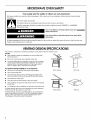
MICROWAVE OVEN SAFETY
Your safety and the safety of others are very important.
We have provided many important safety messages in this manual and on your appliance. Always read and obey all safety
messages.
This is the safety alert symbol.
This symbol alerts you to potential hazards that can kill or hurt you and others.
All safety messages will follow the safety alert symbol and either the word "DANGER" or "WARNING."
These words mean:
You can be killed or seriously injured if you don't immediately
follow instructions.
You can be killed or seriously injured if you don't follow
instructions.
All safety messages will tell you what the potential hazard is, tell you how to reduce the chance of injury, and tell you what can
happen if the instructions are not followed.
VENTING DESIGN SPECIFICATIONS
This section is intended for architectural designer and builder/contractor reference only.
NOTES:
• Vent materials needed for installation are not provided with
microwave hood.
We do not recommend using a flexible metal vent.
Toavoid possible product damage, be sure to vent air outside,
unless using ventless (recirculating) installation. Do not vent
exhaust air into concealed spaces, such as spaces within
walls or ceilings, attics, crawl spaces or garages.
For optimal venting installation, we recommend:
• using roof or wall caps that have back draft dampers
• using a rigid metal vent
• using the most direct route by minimizing the length of the
vent and number of elbows to provide efficient performance
• using uniformly sized vents
• using duct tape to seal all joints in the vent system
• using caulking compound to seal exterior wall or roof opening
around cap
• not installing 2 elbows together, for optimal hood performance
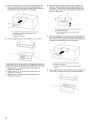
If venting through the wall, be sure that there is proper clearance
within the wall for the damper to open fully.
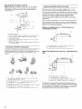
If venting through the roof, and rectangular to round transition is
used, be sure there is at least 3" (7.6 cm) of clearance between
the top of the microwave oven and the transition piece. See
"Rectangular to Round Transition" illustration.
Roof venting
Wall venting
Roof cap
Wall cap

Rectangular to Round Transition
NOTE: The minimum 3" (7.6 cm) clearance must exist between
the top of the microwave oven and the rectangular to round
transition piece so that the damper can open freely and fully.
31/4'' x 10" (8.3 x 25.4 cm) vent system = 73ft (22.2 m) total
A B
6 ft (1.8 m) _{ N
2 ft
(0.6
B
C
3" (7.6 cm)
t
E
F
A. Roof cap
B. 6" (15.2 crn) min. diameter round vent
C. Elbow (for wall venting only)
D. Wall cap
E. 3_" x 10" to 6" (8.3 x 25.4 cm to 15.2 crn)
rectangular to round transition piece
F Vent extension piece, at least 3" (7.6 cm) high
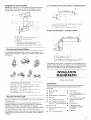
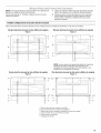
Recommended Standard Fittings
The following length equivalents are for use when figuring vent
length. See the examples in "Recommended Vent Length" later in
this section.
A B C
A. One 3 _" x 10" (8.3 x 25.4 crn) 90° elbow = 25 ft (7.6 m)
B. 1wall cap = 40 ft (12.2 m)
C. 2 ft (0.6 m) + 6 ft (1.8 m) straight = 8 ft (2.4 m)
6" (15.2 cm) vent system = 73 ft (22.2 m) total
_,( 6 ft (1.8 m)
B
C D
A. Two 90° elbows = 20 ft (6.1 m)
B. 1 wall cap = 40 ft (12.2 m)
C. 1rectangular to round transition piece = 5 ft (1.5 m)
D. 2 ft (O.6rn) + 6 ft (1.8 m) straight = 8 ft (2.4 m)
Ifthe existing vent is round, a rectangular to round transition piece
must be used. In addition, a rectangular 3" (7.6 cm) extension vent
between the damper assembly and rectangular to round transition
piece must be installed to keep the damper from sticking.
INSTALLATION
REQUIREMENTS
E F G
A. Rectangular to round transition piece: 3_" x 10" to 6" = 5 ft
(8.3 x 25.4 cm to !5.2 cm = 1.5 rn)
B. Roof cap: 3 ¼" x 10" =24 ft (8.3 x 25.4 cm = 7.3 m)
C. 90° elbow: 3_" x 10" =25 ft (8.3 x 25.4 cm = 7.6 m)
D. 90 ° elbow: 6" = !0 ft (15.2 cm = 3 rn)
E. Wall cap: 3 ¼" x 10" = 40 ft (8.3 x 25.4 cm = !2.2rn)
F. 45 ° elbow: 6" = 5 ft (15.2 cm = 1.5 rn)
G. 90 ° flat elbow: 3¼" x 10" = 10 ft (8.3 x 25.4 cm = 3 m)
Recommended Vent Length
A 31/4"x 10" (8.3 x 25.4 cm) rectangular or 6" (15.2 cm) round vent
should be used.
The total length of the vent system including straight vent,
elbow(s), transitions and wall or roof caps must not exceed the
equivalent of 140 ft (42.7 m) for either type of vent. See
"Recommended Standard Fittings" section for equivalent lengths.
For best performance, use no more than three 90° elbows.
To calculate the length of the system you need, add the equivalent
length for each vent piece used in the system. See the following
examples:
Tools Needed
Gather the required tools and parts before starting installation.
Read and follow the instructions provided with any tools
listed here.
• Measuring tape •
• Pencil •
• Masking tape or thumbtacks
• Scissors
• No. 2 Phillips screwdriver
• No. 3 Phillips screwdriver for
1/4-20 x 3" round-head bolts •
Electric drill
3/16" (5 mm), 3/8" (9.5 mm)
drill bits
• 3/4" (19 mm) hole saw
Stud finder
7/16" socket wrench
(or box wrench) for 1/4" x 2"
lag screws
11/2"(4 cm) diam. hole drill
bit for wood or metal
cabinet
Keyhole saw
Caulking gun and
weatherproof caulking
compound
Duct tape

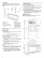
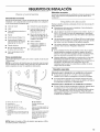
Parts Supplied
For reorder information, see "Replacement Parts" section.
NOTE: The hardware items listed here are for wood studs. For
other types of wall structures, be sure to use appropriate
fasteners.
F
A. 1/4-20 x 3" bolts (6)
B. Washers (2)
C. Toggle nuts (4)
D. 1/4" x 2" lag screws (4)
E. Pewer supply cord bushing (!)
F Damper assembly (for wall or roof
venting)
Not Shown:
Upper cabinet template
Mounting plate (attached to
back of microwave oven)
Aluminum grease filters
Charcoal filters (Depending
on model, charcoal filters
may not be included. See
Use and Care Guide.)
NOTE: Depending on model, aluminum grease filter and charcoal
filter may be combined.
Materials needed
• Standard fittings for wall or roof venting. See "Venting Design
Specifications" section.
Check the opening where the microwave oven will be installed.
The location must provide:
• Minimum installation dimensions. See "Installation
Dimensions" illustration.
• Minimum one 2" x 4" (50.8 x 101.6 mm) wood wall stud and
minimum 3/8" (9.5 mm) thickness drywall or plaster/lath within
cabinet opening.
• Support for weight of 150 Ibs (68 kg), which includes
microwave oven and items placed inside the microwave oven
and upper cabinet.
• Grounded electrical outlet inside upper cabinet. See
"Electrical Requirements" section.
NOTES: T
• If installing the microwave oven near a left sidewall, make sure
there is at least 6" (15.2 cm) of clearance between the wall and
the microwave oven, so that the door can open fully. 161/4,,
• Some cabinet and building materials are not designed to (41.3cml
withstand the heat produced by the microwave oven for |
cooking. Check with your builder or cabinet supplier to make
1
sure that the materials used will not discolor, delaminate or
sustain other damages.
Special Requirements
For Wall Venting Installation Only:
• The 12" x 4" (30.5 x 10.2 cm) cutout area must align with the
rectangular hole in the mounting plate.
• Cutout must be free of any obstructions so that the vent tube
fits properly, and the damper blade opens freely and fully.
For Roof Venting Installation Only:
• If using rectangular to round transition piece, the 3" (7.6 cm)
clearance needs to exist above the microwave oven so that
the damper blade can open freely and fully. See "Rectangular
to Round Transition" illustration in "Venting Design
Specifications" section.
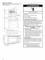
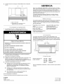
Installation Dimensions
NOTE: The grounded 3 prong outlet must be inside the upper
cabinet. See "Electrical Requirements" section.
}
66" (167.6 cm) rain.
A. 2" x 4" wall stud
B. Grounded 3 prong outlet
T
15"
(38.1 cm)

GROUNDING iNSTRUCTiONS
Electrical Shock Hazard
Plug into a grounded 3 prong outlet.
Do not remove ground prong.
Do not use an adapter.
Do not use an extension cord.
Failure to follow these instructions can result in death,
fire, or electrical shock.
Observe all governing codes and ordinances. A 120 Volt, 60 Hz,
AC only, 15- or 20-amp fused electrical supply (or circuit breaker)
is required. (A time-delay fuse or circuit breaker is recommended.)
It is recommended that a separate circuit serving only this
appliance be provided.
[] For all cord connected appliances:
The microwave oven must be grounded. In the event of
an electrical short circuit, grounding reduces the risk of
electric shock by providing an escape wire for the electric
current. The microwave oven is equipped with a cord
having a grounding wire with a grounding plug. The plug
must be plugged into an outlet that is properly installed
and grounded.
WARNING: Improper use of the grounding plug can
result in a risk of electric shock. Consult a qualified
electrician or serviceman if the grounding instructions are
not completely understood, or if doubt exists as to whether
the microwave oven is properly grounded.
Do not use an extension cord. If the power supply cord is
too short, have a qualified electrician or serviceman install
an outlet near the microwave oven.
SAVE THESE iNSTRUCTiONS
INSTALLATIONINSTRUCTIONS
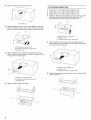
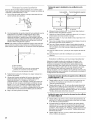
1. Remove any remaining contents from the microwave oven
cavity.
2. Remove the mounting plate by peeling off the strips of tape
that attach it to the back of the microwave oven, and set the
mounting plate aside.
A B C
i
ii
iili
A.Back of microwave oven
B.Mounting plate
C.Tape (multiplelocations)
3. Tape microwave oven door closed so that door does not
swing open while microwave oven is being handled.
NOTE: Do not grip or use the door or door handle while the
microwave oven is being handled.
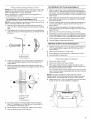
otote Deflectx} '
The microwave oven is set for ventless (recirculating) installation.
For wall or roof venting, changes must be made to the venting
system.
NOTE: Skip this section if you are using ventless (recirculating)
installation. Keep the damper assembly in case the venting
method is changed, or the microwave oven is reinstalled in
another location where wall or roof venting may be used.
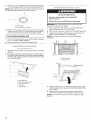
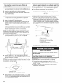
Wall Venting Installation Only
1. Remove 5 screws attaching damper plate to top of microwave
oven exterior, then lift off damper plate.
A. Damper plate
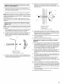
2. Keep damper plate and screws together and set aside.

3. Slideairdeflectoroutofmicrowaveoven.
4.
5,
A.Air deflector
Rotate air deflector front to back so that deflector vanes face
the back of the microwave oven, and the exhaust port (open
end) of air deflector aligns with microwave oven exhaust port.
A
C
A. Microwave oven exhaust port
B. Air deflector exhaust port (open end)
C. Deflector vanes
Slide air deflector into the back of the microwave oven as
shown, making sure its exhaust port (open end) aligns with the
microwave oven exhaust port.
A
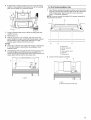
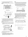
Roof Venting Installation Only
1. Repeat Step 1 from "Wall Venting Installation Only."
2. Repeat Step 2 from "Wall Venting Installation Only."
3. Repeat Step 3 from "Wall Venting Installation Only."
4. Rotate air deflector so that deflector vanes face the top of the
microwave oven, and the exhaust port (open end) of air
deflector aligns with microwave oven exhaust port.
A
A. Microwave oven exhaust port
B. Deflector vanes
C. Air deflector exhaust port (open end)
Slide air deflector into the back of the microwave oven as
shown, making sure its exhaust port (open end) aligns with the
microwave oven exhaust port.
A. Microwave oven exhaust port
B. Air deflector exhaust port (open end)
C. Deflector vanes
6. Reattach damper plate with screws.
A. Microwave oven exhaust port
B. Deflector vanes
C. Air deflector exhaust port (open end)
Reattach damper plate at corners with 4 screws. Save the fifth
screw for later use.

bscc e Stud(s}
NOTE: If no wall studs exist within the cabinet opening, do not 1. Using a stud finder, locate the edges of the wall stud(s) within
install the microwave oven, the opening.
See illustrations in "Possible Wall Stud Configurations," 2. Mark the center of each stud, and draw a plumb line down
each stud center. See illustrations in "Possible Wall Stud
Configurations."
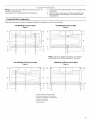
Possible Wall Stud Configurations
These depictions show examples of preferred installation configurations with the mounting plate.
No Wall Studs at Corner Holes
Figure 1
No Wall Studs at Corner Holes
Figure2
i
B I/ i
....... m k I
...... ( L __::_ rrs';_s';'%L;':s"_'w_'_'"C
°o°o°o°o°o°o°:o0........: d OoOoOoOoOoOooI
!.
1;; 12i> _"E
i ..... J J"
) o o o o o o o o o o o o o o o o o o o o o
A................. o o o o o o o o o o o o o o o o • ...............
F
I B
_ i Di i
! i
I li
NOTE: If wall stud is behind vent opening, only ventless
(recirculating) or roof venting installation can be done.
One Wall Stud at Two Corner Holes
Figure3
Wall Studs at All Four Corner Holes
Figure4
, v iI
A................• o -f o i
.............A E A,E .......... _ °
B II [ II i
o°o o°o ° °o°o °o°o° ° _, °o°o° o°o°o°
o oo i
ooOoOot o O-oooooooooooooooooooooooo ° o oOo o oOoOo_
a o o o o o oooooooooooooooooooooooo o o o o o o
I
......................... i
i = ...................... ' i
i ......... i
_ ................... _ !o ........... _o
o o o ,'s o o o o o o o o o o o o o o o o o o o o o o o o o o o ....
A,E
/-_ ................._.o o o o o o o o o ! o o o o o o o o o_. ;=,...¢.tp_""""'/'1, _ o
.......... i ! ...................! _:/ y" i
i'; F >"F I [ F-'_'] [ .........F
i: ! :i i ! i:
D .i; ! _........D D [ [ _'"""'" D
_i _ i _i _ i i
i , i i i '
A. Corner holes (on mounting plate)
B. Cabinet opening vertical centerline
C. Wall vent opening (on mounting plate)
D. Wall stud centerlines
E. Holes for lag screws
F. Support tabs

The microwave oven must be installed on a minimum of 1 wall
stud, preferably 2, using a minimum of 1 lag screw, preferably 2 or
more.
1. Using measuring tape, find and clearly mark the vertical
centerline of the opening.
A _
A. Centerline
2. With the support tabs facing forward (see illustrations in
"Possible Wall Stud Configurations" in "Locate Wall Stud(s)"
section), align the mounting plate to the centefline on the wall,
making sure it is level, and that the top of the mounting plate
is butted up against the bottom edge of the upper cabinet.
NOTE: If the front edge of the upper cabinet is lower than the
back edge, lower the mounting plate so that its top is level with
the front edge of the cabinet.
A ..........
C
B
A. Rear wall
B. Mounting plate
C. Top of mounting plate must align
with front edge of cabineL
D. Front edge of upper cabinet
3. Holding the mounting plate in place, mark the 4 corner holes.
4. Find the wall stud centerline(s) marked in Step 2 of "Locate
Wall Stud(s)," and mark at least 1, preferably 2 or more, hole(s)
through the mounting plate, closest to the centerline(s). See
figures 1, 2 and/or 3 in "Possible Wall Stud Configurations" in
"Locate Wall Stud(s)" section. The blackened holes in the
shaded areas are ideal hole locations.
5. Set mounting plate aside.
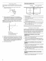
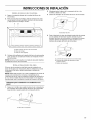
Wall Venting Installation Only
Centerline
t
4" (10.2 cm)
6" (15.2 cm)
•
6" (15.2 cm)
Upper Cabinet Bottom
f-'-' I
6. Mark the centerline 3/8" (1 cm) down from the bottom edge of
the upper cabinet.
7. Using measuring tape, measure out 6" (15.2 cm) on both sides
of the centefline, and mark.
8. Measure down 4" (10.2 cm) from the mark made in Step 6,
and mark.
9. Using a straightedge, draw the 2 horizontal, level lines through
the marks made in steps 6 and 8.
10. Draw the 2 vertical, plumb lines down from the marks made in
Step 7 to complete the 12" x 4" (30.5 x 10.2 cm) rectangle.
This is the venting cutout area.
11. Cut a 3/4" (19 mm) hole in one corner of the cutout area.
12. Using a keyhole saw, cut out the venting cutout area.
In addition to being installed on at least 1wall stud, the mounting
plate must attach to the wall at all 4 corner holes. If the holes are
not over wall studs, use four 1/4-20 x 3" bolts with toggle nuts; if 2
holes are over wall studs, use 2 each of lag screws and 1/4-20 x
3" bolts with toggle nuts; or if all 4 holes are over wall studs, use
4 lag screws. Following are 3 installation configurations.
Installation for No Wall Studs at Corner Holes
(Figures 1 & 2)
1. Drill 3/4" (19 mm) holes through the wall at all 4 corner holes
marked in Step 3 of "Mark Rear Wall."
2. Drill 3/16" (5 mm) hole(s) into the wall stud(s) at the hole(s)
marked in Step 4 of "Mark Rear Wall." Refer to figures 1and 2
in "Possible Wall Stud Configurations" in "Locate Wall Stud(s)"
section.
Installation for One Wall Stud at Two Corner Holes
(Figure 3)
1. Drill 3/16" (5 mm) holes into the wall stud at the 2 corner holes
marked in Step 3 of "Mark Rear Wall."
2. If installing on a second wall stud, drill 3/16" (5 mm) hole(s)
into the wall stud at the holes marked in Step 4 of "Mark Rear
Wall." Refer to Figure 3 in "Possible Wall Stud Configurations."
in "Locate Wall Stud(s)" section.
3. Drill 3/4" (19 mm) holes through the wall at the other 2 corner
holes.
Installation for Wall Studs at All Four Corner Holes
(Figure 4)
1. Drill 3/16" (5 mm) holes into the studs at the 4 corner holes
marked in Step 3 of "Mark Rear Wall."

Afi csch Moun s e o
NOTE: Secure the mounting plate to the wall at all 4 corner holes
drilled into the wall studs and/or drywall using either 1/4-20 x 3"
bolts and toggle nuts or 1/4 x 2" lag screws,
Refer to illustrations in "Possible Wall Stud Configurations" in
"Locate Wall Stud(s)" section,
No Wall Studs at Corner Holes (Figures I & 2)
NOTE: The mounting plate must also be secured to the wall on at
least 1 wall stud as well as at all 4 corners.
1. With the support tabs of the mounting plate facing forward,
insert 1/4-20 x 3" bolts through all 4 corner holes of mounting
plate.
2. Start toggle nuts on bolts from the back of the mounting plate.
Leave enough space for the toggle nuts to go through the wall
and open.
B
A .............................
_s
A. 1/4-20x3" bolt
B. Mounting plate
C. Spring toggle nut
3. Position mounting plate on the wall, making sure that the top
of the mounting plate is aligned with the front edge of the
upper cabinet.
4. Push the 4 bolts with toggle nuts through the drywall, and
finger tighten the bolts to make sure toggle nuts have opened
against drywall.
C
B"
A. 1/4-20x3" bolt
B. Mounting plate
C. Drywall
D. Spring toggle nut
5. Insert lag screw(s) into the holes drilled into wall stud(s) in
Step 2 of "Installation for No Wall Studs at Corner Holes" in
the "Drill Holes in Rear Wall" section.
6. Check alignment of mounting plate, making sure it is level.
7. Securely tighten all lag screws and bolts.
One Wall Stud at Two Corner Holes (Figure 3)
1. With the support tabs of the mounting plate facing forward,
insert 1/4-20 x 3" bolts through the 2 corner holes that fit over
the two 3/4" (19 mm) holes drilled in Step 2 of "Installation for
One Wall Stud at Two Corner Holes" in the "Drill Holes in Rear
Wall" section.
2. Start toggle nuts on the bolts from the back of the mounting
plate. Leave enough space for the toggle nut to go through
the wall and to open.
3. Position mounting plate on the wall, making sure that the top
of the mounting plate is aligned with the front edge of the
upper cabinet.
4. Push the 2 bolts with toggle nuts through the drywall, and
finger tighten the bolts to make sure toggle nuts have opened
against drywall
5. Insert 2 lag screws into the remaining 2 corner holes.
6. If installing on a second wall stud, insert lag screw(s) into the
other hole(s) drilled in Step 2 of "Installation for One Wall Stud
at Two Corner Holes" in the "Drill Holes in Rear Wall" section.
7. Check alignment of mounting plate, making sure it is level.
8. Securely tighten all lag screws and bolts.
Wall Studs at All Four Corner Holes (Figure 4}
1. Position mounting plate on the wall, making sure that the top
of the mounting plate is aligned with the front edge of the
upper cabinet.
2. Insert lag screws into the 4 corner holes.
3. Check alignment of mounting plate, making sure it is level.
4. Securely tighten all lag screws.
1=
2.
3.
Disconnect power to outlet.
Remove all contents from upper cabinet.
Place Upper Cabinet Template against the bottom of the
upper cabinet. Make sure the template centerline aligns with
the vertical centerline on the rear wall.
The "rear wall" arrows must be against the rear wall so that the
holes cut into the upper cabinet align with the holes in the top
of the microwave oven.
NOTE: If the upper cabinet has a frame around it, trim the
template edges so that it fits inside the frame, against the upper
cabinet bottom. The template has trim lines to use as guides.
4. Make sure the 107_e'' (26.5 cm) dimension from the rear wall to
points "D" and "E" on the template is maintained.
O ©

5. Cut the 11/2"(3.8 cm) diameter hole at the circular shaded area
"G" on the template. This hole is for the power supply cord.
NOTE: Ifupper cabinet is metal, the supply cord bushing needs to
be installed around the supply cord hole, as shown.
A. Metal cabinet
B. Power supply cord bushing
6. Drill 3/8" (10 mm) holes at points "D" and "E" on the template.
These are for two 1/4-20 x 3" round-head bolts and washers
used to secure the microwave oven to the upper cabinet.
For Roof Venting Installation Only
7. Cut 3/4" (19 mm) hole at one corner of the shaded rectangular
area "F" on Upper Cabinet Template.
8. Using a keyhole saw, cut out the rectangular area.
.......... l.._Ull p_ss Bv;£,>el l,,_li!
I=
2.
Check that damper blade moves freely, and opens toward the
wall fully.
Push damper assembly through opening in mounting plate so
that tabs in damper assembly lock damper assembly against
mounting plate. Long tab of damper assembly must be to left
side of mounting plate.
A ....................................
A. Mounting plate
B. Mounting plate opening
C. Damper assembly
D. Long tab
E. Damper blade
! sto!! tse Mic eve Oven
Excessive Weight Hazard
Use two or more people to move and install
microwave oven.
Failure to do so can result in back or other injury.
IMPORTANT: The control side of the unit is the heavy side.
Handle the microwave oven gently.
1. Place a washer on each 1/4-20 x 3" bolt and place inside
upper cabinet near the 3/8" (10 mm) holes.
2. Make sure the microwave oven door is closed and taped shut.
3. Using 2 or more people, lift microwave oven and hang it on
support tabs at the bottom of mounting plate.
NOTE: Do not grip or use the door or door handle during
installation.
L
A. Mounting plate
B. Support tabs
4. With front of microwave oven still tilted, thread power supply
cord through the power supply cord hole in the bottom of the
upper cabinet.
5. Rotate microwave oven up toward upper cabinet. Push
microwave oven against mounting plate and hold in place.
NOTE: If microwave oven does not need to be adjusted, skip
steps 6-8.
10

6.
If adjustment is required, rotate microwave oven downward.
Using 2 or more people, lift microwave oven off of mounting
plate, and set aside on a protected surface.
7. Loosen mounting plate screws. Adjust mounting plate and
retighten screws.
8. Repeat steps 3-5.
g. With the microwave oven centered, and with at least one
person holding it in place, insert bolts through upper cabinet
into microwave oven. Tighten bolts until there is no gap
between upper cabinet and microwave oven.
NOTES:
• Some upper cabinets may require bolts longer or shorter than
3" (7.6 cm). Longer or shorter bolts are available at most
hardware stores.
Overtightening bolts may warp the top of the microwave oven.
To avoid warping, wood filler blocks may be added. The
blocks must be the same thickness as the space between the
upper cabinet bottom and the microwave oven.
A n
A. Bolts
For Roof Venting Installation Only
1. Insert damper assembly through the cabinet cutout so that the
long tab of the damper assembly slides under the raised tabs
of the damper plate. Then secure with screw removed in
Step 1 of "Rotate Air Deflector."
NOTE: The screw cannot be installed if the damper assembly is
not positioned as shown.
B
E
A. Raised tabs
B. Damper assembly
C. Screw
D. Upper cabinet cutout
E. Long tab
F. Damper plate
Connect vent to damper assembly.
A B
[
A. Vent
B. Damper assembly (under vent)
11

Comple e st<sllcAion
Refer to the Use and Care Guide for instructions on how to
install filters into your model.
Electrical Shock Hazard
Plug into a grounded 3 prong outlet.
Do not remove ground prong.
Do not use an adapter.
Do not use an extension cord,
Failure to follow these instructions can result in death,
fire, or electrical shock.
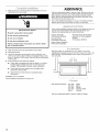
ASSISTANCE
Call your authorized dealer or service center. When you call, you
will need the microwave oven model number and serial number.
Both numbers can be found on the model and serial number
plate, which is located behind the microwave oven door on the
front frame of the microwave oven.
If you need additional assistance, call us at our toll free number
listed in the Use and Care Guide, or visit us on the Web.
If any of the installation hardware needs to be replaced, call us at
our toll free number listed in the Use and Care Guide, and
reference the appropriate part number listed here.
Damper Assembly
Part Number 8205558
Mounting Plate
Part Number 8205400
Upper Cabinet Template
Part Number 8205925
Mounting Screw Kit (includes
parts A-E in "Parts Supplied"
section)
Part Number 8205947
2=
3.
4.
5=
Plug microwave oven into grounded 3 prong outlet.
Reconnect power.
Check the operation of microwave oven by placing 1cup
(250 mL) of water on the turntable, and programming a cook
time of I minute at 100% power. Test vent fan by touching the
vent fan pad.
If the microwave oven does not operate:
• Check that a household fuse has not blown, or a circuit
breaker tripped. Replace the fuse or reset the circuit
breaker. If the problem continues, call an electrician.
• Check that the power supply cord is plugged into a
grounded 3 prong outlet.
• See the Use and Care Guide for troubleshooting
information.
Installation is now complete.
Save Installation Instructions for future use.
A. Filler panels
Filler Panel Kit Number 8171336 White
8171337 Black
8171338 Biscuit
8171339 Stainless Steel
99403 Almond
See your authorized dealer or service center for details.
12

SEGURIDAD DELA COMBINACION MICROONDAS
CAMPANA
Su seguridad y la seguridad de los demas es muy importante.
Hemos incluido muchos mensajes importantes de seguridad en este manual yen su electrodomestico. Lea y obedezca siempre
todos los mensajes de seguridad.
Este es el sfmbolo de advertencia de seguridad.
Este sfmbolo le llama la atencion sobre peligros potenciales que pueden ocasionar la muerte o una lesion a
usted y a los demas.
Todos los mensajes de seguridad iran a continuacidn del simbolo de advertencia de seguridad y de la palabra
"PELIGRO" o "ADVERTENCIA". Estas palabras significan:
Si no eigue lae instruccionee de inmediato, usted puede
morir o sufrir una lesion grave.
Si no eigue lae instrucciones, usted puede morir o eufrir
una lesion grave.
Todos los mensajes de seguridad le diran el peligro potencial, le diran como reducir las posibilidades de sufrir una lesidn y Io que
puede suceder si no se siguen las instrucciones.
ESPECIFICACIONESPARA ELDISENO DELA VENTILACION
Esta secci6n ha sido creada solamente para referencia del
diseSador arquitect6nico y constructor/contratista.
NOTAS:
• Los materiales de ventilaci6n necesarios para la instalaci6n no
se proveen con la combinaci6n microondas campana.
• No recomendamos usar un ducto de escape de metal flexible.
• Para evitar posibles da_os al producto, asegt]rese de ventilar
el aire hacia el exterior, a menos que se trate de una
instalacidn sin ducto de escape (con recirculaci6n). No ventile
el aire de escape en espacios ocultos, tales como espacios
dentro de paredes o techos, desvanes, espacios angostos o
garages.
Para una instalacibn con ventilacibn 6ptima,
recomendamos:
• usar cubiertas de techo o de pared que tengan compuertas
de contratiro
usar un ducto de escape de metal r(gido
usar la ruta mas directa reduciendo al minimo el largo del
ducto y el nQmero de codos para proveer un funcionamiento
eficaz
Ventilaci6n a traves del techo Cubierta del techo
• usar ductos de escape de tama_o uniforme
• usar cinta para ductos para sellar todas las juntas en el
sistema de ventilaci6n
Ventilaci6n atraves de la pared Cubierta de la pared
• usar un compuesto de calafateo para sellar la abertura de la
pared o el techo exterior alrededor de la cubierta
• para un funcionamiento 6ptimo de la campana, no instalar
2 codos juntos
Siva atener la ventilaci6n a traves de la pared, cerci6rese de que
haya el espacio adecuado dentro de la pared para poder abrir
completamente la compuerta.
Siva a tener la ventilaci6n a traves del techo y va a usar un tubo
de ajuste rectangular a redondo, cerci6rese de que haya un
espacio de por Io menos 3" (7,6 cm) entre la parte superior del
homo de microondas y el tubo de ajuste. Vea la ilustraci6n "Tubo
de ajuste rectangular a redondo".
13

Tubo de ajuste rectangular a redondo
NOTA: Debe haber un espacio minimo de 3" (7,6 cm) entre la
parte superior del homo de microondas y el tubo de ajuste
rectangular a redondo para poder abrir la compuerta libre y
completamente.
B
C
E
F
A. Cubierta del techo
B. Ducto de escape redondo con di#metro mfn. de 6" (15,2 cm)
C. Code (selamente para la ventilacidn a trav_s de la pared)
D. Cubierta de la pared
E. Tubo de ajuste rectangular a redondo de 3 _" x 10" a 6" (8,3 x
25,4 cm a 15,2 cm)
F. Pieza para la extensidn del ducto de escape, per Io menos de
3" (7,6 cm) de altura
Accesorios corrientes recomendados
Los largos equivalentes que siguen son para usarse cuando
calcule el largo del ducto de escape, Vea los ejemplos en "Largo
recomendado del ducto de escape", mas adelante en esta
secci6n.
A B C
E F G
A. Tube de ajuste rectangular a redondo: 3 _" x 10" a 6" = 5 pies
(8,3 x 25,4 cm a 15,2 cm = 1,5 m)
B. Cubierta del techo: 3 ¼" x 10" = 24 pies (8,3 x 25,4 cm = 7,3 m)
C. Codo de gO°: 3 _" x 10" = 25 pies (8,3 x 25,4 cm = 7,6m)
D. Codo de 90°: 6" = 10 pies (15,2 cm = 3 m)
E.Cubierta de la pared: 3¼" x 10" = 40 pies (8,3 x 25,4 cm = !2,2 m)
F. Codo de 45°: 6" = 5 pies (15,2 cm = 1,5 m)
G. Codo piano de 90°: 3 _" x 10" = 10 pies (8,3 x 25,4 cm = 3 m)
Largo recomendado del ducto de escape
Debera usarse un ducto de escape rectangular de 31/4"x 10"
(8,3 x 25,4 cm) o un ducto de escape redondo de 6" (15,2 cm).
La Iongitud total del sistema de ventilacidn incluyendo el ducto de
escape derecho, el(los) codo(s), los tubos de ajuste y las cubiertas
de la pared odel piso no debera exceder del equivalente a
140 pies (42,7 m) para cualquier tipo de ventilacidn. Vea la
seccidn "Accesorios corrientes recomendados" para los largos
equivalentes.
Para un mejor funcionamiento, no use mas de tres codos de 90°.
Para calcular el largo del sistema que va a necesitar, agregue el
largo equivalente para cada pieza de ventilacidn a ser usada en el
sistema. Vea los ejemplos siguientes:
Sistema de ventilacibn de 31/4'' x 10" (8,3 x 25,4 cm) =
73 pies (22,2 m) en total
A
6 pies (1,8 m)
t<
(0,6 m)2__U
C
B
A. Uncodo de 90°de 3¼" x 10" (8,3x 25,4 cm) = 25pies (7,6 m)
B. 1cubierta de pared = 40 pies (12,2 m)
C. 2 pies (0,6 m) + 6 pies (1,8 m) recto = 8 pies (2,4 m)
Sistema de ventilacibn de 6" (15,2cm) = 73 pies (22,2 m) en
total
A B
C D
A. Dos codos de 90° = 20 pies (6,1 m)
B. 1 cubierta de pared = 40 pies (12,2 m)
C. 1 tubo de ajuste rectangular a redondo = 5pies (1,5 m)
D. 2 pies (0,6 m) + 6 pies (1,8 m) recto = 8 pies (2,4 m)
Si el ducto de escape existente es redondo, debera usarse un
tubo de ajuste rectangular a redondo. Tambien debera instalarse
un ducto de escape de extensidn rectangular de 3" (7,6 cm) entre
el ensamblaje de la compuerta y el tubo de ajuste rectangular a
redondo para evitar que la compuerta se adhiera.
14

REQUlSlTOSDEINSTALACION
Herramientas necesarias
ReQna las herramientas y piezas necesarias antes de comenzar la
instalaci6n. Lea y siga las instrucciones provistas con cualquiera
de las herramientas enlistadas aqui.
• Cinta de medir •
• Lapiz •
• Cinta adhesiva protectora o
chinches
• Tijeras •
• Destornillador Phillips N° 2
• Destornillador Phillips N° 3
para los pernos de cabeza •
redonda de 1/4-20 x 3"
• Taladro electrico
• Brocas de barrena de 3/16"
(5 mm) y 3/8" (9,5 mm) •
• Sierra perforadora de3/4"
(19 mm)
Detector de pies derechos
Llave de tube de 7/16" (o
Ilave de cubo) para los
tirafondos de 1/4" x 2"
Broca de barrena para un
orificio con un diam. de 11/2"
(4 cm) para el gabinete de
madera o de metal
Sierra caladora
Pistola para calafateo y
masilla para calafateo a
prueba de agua
Cinta para tubes
Piezas suministradas:
Para recibir informaci6n sobre c6mo volver a pedir, yea la secci6n
"Refacciones".
NOTA: Los art(culos de ferretefia que se enumeran aqu( son para
los pies derechos de madera. Para otros tipos de estructuras de
pared, asegQrese de usar los sujetadores adecuados.
F
Materiales necesarios
Accesorios corrientes para la ventilaci6n atrav_s de la pared o del
techo. Vea la secci6n "Especificaciones para el dise_o de la
ventilaci6n'.
Reqf stos #_2®' _'_db coC @
Revise la abertura donde se instalara el homo de microondas. El
lugar debe tener:
• Dimensiones m(nimas para la instalaci6n. Vea la ilustraci6n
"Dimensiones de instalaci6n".
• Un pie derecho de pared de madera come minimo, de 2" x 4"
(50,8 x 101,6 mm) y un muro de mamposteria o yeso/list6n
con un espesor m[nimo de 3/8" (9,5 mm) dentro de la abertura
del gabinete.
• Un soporte para un peso de 150 libras (68 kg), el cual incluye
el horno de microondas y los objetos que se coloquen dentro
del mismo, asi come tambien en el gabinete superior.
• Un contacto electrico conectado atierra dentro del gabinete
superior. Vea la secci6n "Requisites electricos".
NOTAS:
• Siva a instalar el horno de microondas cerca de una pared
lateral izquierda, asegQrese de dejar un espacio de por Io
menos 6" (15,2 cm) entre la pared y el homo de microondas,
para que la puerta se pueda abrir en toda su extensi6n.
• AIgunos gabinetes y materiales de construcci6n no han sido
dise_ados para resistir el calor que produce el homo de
microondas durante la cocci6n. Verifique con el constructor o
distribuidor de gabinetes para asegurarse de que los
materiales que se usen no se descoloren, astillen ni sufran
ningQn otto tipo de dar_o.
Requisitos especiales
Solamente para la instalaci6n con ventilaci6n en la pared:
• El Area del recorte de 12" x 4" (30,5 x 10,2 cm) debera
alinearse con el orificio rectangular en la placa de montaje.
• El recorte debera estar libre de cualquier obstrucci6n para
que el tubo de ventilaci6n encaje como es debido y la hoja de
la compuerta se abra libre y completamente.
Solamente para la instalaci6n con ventilaci6n en el techo:
• Si usa un tube de ajuste rectangular a redondo, debera haber
un espacio de 3" (7,6 cm) por encima del homo de
microondas, para que la hoja de la compuerta pueda abrirse
libre y completamente. Vea la ilustraci6n "Tube de ajuste
rectangular a redondo" en la secci6n "Especificaciones para
el dise_o de la ventilaci6n'.
A. Pernos de 1/4-20 x 3" (6)
B. Arandelas (2)
C. Tuercas de ajuste (4)
D. Tirafondos de 1/4" x 2" (4)
E. Ferro del cable de suministro de
energfa (1)
F. Ensamblaje de la cempuerta (para la
ventilacidn a tray,s de la pared o del
techo)
No se muestra:
Plantilla del gabinete
superior
Placa de mentaje (sujeta a la
parte posterior del homo de
micreendas)
Filtros para grasa de aluminio
Filtres de carbdn (SegOn el
modelo, tal vez no se
incluyan filtros de carbdn.
Vea el Manual de Uso y
Cuidade.)
NOTA: SegQn el modelo, el filtro de aluminio para grasa y el filtro
de carb6n pueden combinarse.
15

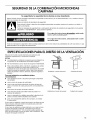
Dimensiones de instalacibn
NOTA: El contacto de pared de conexi6n a tierra de 3 terminaies
debe estar dentro del gabinete superior. Vea la seccidn
"Requisites electricos".
A B
12" (30,5 cm) rain.
14" (35,6 cm) m_x.
66" (167,6 cm) min.
..............................
A. Pie derecho de pared 2" x 4"
B. Contacto de 3 terminales con conexidn a tierra
T
161/4 `'
(41,3 cm'
T
15"
38,1 cm)
1
Peligro de Choque Electrico
Conecte a un contacto de pared de conexi6n a tierra de
3 terminalee.
No quite la terminal de conexion a tierra.
No use un adaptador.
No use un cable electrico de extensi6n.
No eeguir eetas inetrucciones puede ocaeionar
la muerte, incendio o choque el_ctrico.
Cumpla con todos los c6digos y 6rdenes vigentes. Se requiere un
suministro de 120 voltios, 60 Hz, Qnicamente CA de 15 6
20 amperios con fusible (o disyuntor). (Se recomienda un fusible
de acci6n retardada o un disyuntor.) Se recomienda que se use un
circuito dedicado exciusivamente para este aparato
eiectrodom_stico.
INSTRUCCIONES PARA LA CONEXION
A TIERRA
[] Para todos los aparatoe electrodomeeticoe de
conexion con cable:
El homo de microondas debe estar conectado a tierra. En
case de que se produzca un corto circuito, la conexi6n a
tierra reduce el riesgo de electrocucion per medio de un
alambre de escape para la corriente electrica. El homo de
microondas esta equipado con un cable que tiene un
alambre de conexi6n a tierra con un enchufe para
conexi6n a tierra. El enchufe debe estar conectado a un
tomacorriente que esta correctamente instalado y
conectado a tierra.
ADMERTENCIA: El use incorrecto de la conexi6n a
tierra puede resultar en riesgo de electrocucion. Consulte
con un electricista o tecnico calificado si las instrucciones
para conexion a tierra no se entienden bien o si hay alguna
duda con respecto a la correcta conexi6n a tierra del homo
de microondas.
No use un cable de extension. Si el cable es muy corto,
haga que un electricista o tecnico caificado instale un
tomacorriente cerca del homo de micreondas.
GUARDE ESTAS INSTRUCClONES
16

INSTRUCCIONESDE INSTALACION
I.
2.
de n otGe
Saque el contenido restante de la cavidad del homo de
microondas.
Para sacar la placa de montaje, pele las bandas de la cinta
que la sujetan a la parte posterior del homo de microondas
y deje la placa de montaje a un lado.
2. Mantenga juntos la placa de la compuerta de tiro y los
tornillos y dejelos a un lado.
3. Deslice el desviador de aire fuera del horno de microondas.
A B C
®(
O--
irf'%°
• eg ee eel_jeQReeRjoReeRoeR=oR=oJ'Qg = • = ® = • =e Rg e_
\ O'_ ...................... _O
= • • • • • • • • • • • • • • • • • e • • • •
A. Parte posterior del homo de microondas
B. Placa de montaje
C. Cinta (en varios lugares)
3. Coloque cinta adhesiva en la puerta del homo de microondas
para que esta no se balancee mientras se manipula el homo
de microondas.
NOTA: No tome o use la puerta o la manija de la puerta mientras
se manipula el homo de microondas.
El homo de microondas ha sido fijado para la instalaci6n sin
ducto de escape (con recirculaci6n). Para la ventilaci6n a traves
de la pared o del techo, debera modificarse el sistema de
ventilaci6n.
NOTA: Saltee esta secci6n siva a usar la instalaci6n sin ducto de
escape (con recirculaci6n). Conserve el ensamblaje de la
compuerta de tiro en caso de cambiar el metodo de ventilaci6n o
siva avolver a instalar el homo de microondas en otro lugar en
donde pueda usar la ventilaci6n a traves de la pared o del techo.
Solamente para la instalacibn con ventilacibn en la
pared
1. Saque los 5 tornillos que sujetan la placa de la compuerta de
tiro al exterior de la parte superior del homo de microondas;
luego levante y saque la placa de la compuerta de tiro.
A
A. Desviador de aire
Rote el desviador de aire de adelante hacia atras de manera
que las paletas del desviador queden mirando la parte
posterior del horno de microondas y la lumbrera de escape
(extremo abierto) del desviador de aire se alinee con la
lumbrera de escape del homo de microondas.
A
C
A. Lumbrera de escape del homo de microondas
B. Lumbrera de escape del desviador de aire
(extreme abierto)
C. Paletas del desviador
A. Placa de la compuerta
17

5=
Deslice el desviador de aire dentro de la parte posterior del
homo de microondas, como se muestra, cerciorandose de
que la lumbrera de escape (extreme abierto) este alineada con
la lumbrera de escape del homo de microondas.
A
U
A. Lumbrera de escape del homo de microondas
B. Lumbrera de escape del desviador de aire
(extreme abierto)
C. Paletas del desviador
6. Vuelva a sujetar la placa de la compuerta con los tornillos.
Rote el desviador de aire de manera que las paletas del
desviador queden mirando la parte superior del homo de
microondas, y la lumbrera de escape (extremo abierto) del
desviador de aire se alinee con la lumbrera de escape del
homo de microondas.
A
J
A. Lumbrera de escape del home de microondas
B. Paletas del desviador
C. Lumbrera de escape del desviador de aire
(extreme abierto)
Deslice el desviador de aire dentro de la parte posterior del
homo de microondas, como se muestra, cerciorandose de
que la lumbrera de escape (extreme abierto) este alineada con
la lumbrera de escape del homo de microondas.
Solamente para la instalacibn con ventilacibn en el techo
1. Repita el paso 1 de "Solamente para la instalacidn con
ventilaci6n en la pared".
2. Repita el paso 2 de "Solamente para la instalacidn con
ventilaci6n en la pared".
3. Repita el paso 3 de "Solamente para la instalacidn con
ventilaci6n en la pared".
A. Lumbrera de escape del homo de microondas
B. Paletas del desviader
C. Lumbrera de escape del desviador de aire (extreme
abierto)
Vuelva a ajustar la placa de la compuerta en las esquinas con
4 los tornillos. Guarde el 5to tornillo para usarlo despues.
18

NOTA: Si no hay pies derechos de pared dentro de ia abertura del
gabinete, no instale el homo de microondas.
Vea las ilustraciones en "Posibles configuraciones de los pies
dereches de pared".
1, Ubique los extremes del(de los) pie@)derecho(s) de pared
dentro de la abertura con un detector de pies derechos.
2. Marque el centro de cada pie derecho y trace una linea a
plomo debajo del centro de cada pie derecho. Vea las
ilustraciones en "Posibles configuraciones de los pies
derechos de pared".
Posibles conflguraciones de los pies derechos de pared
Estas representaciones muestran ejempios de ias configuraciones de instaiaci6n preferidas con ia piaca de montaje.
Sin pies derechos de pared en los orificios de esquina
Figura 1
Sin pies derechos de pared en los orificios de esquina
Figura2
_i_ I _i_
o o o o o o o ,.,2,,o2,,,.2.,,,.,2,,o2, _
o o o o
....... i: .....
o o o o o oooooooo ;
r ,
B
oooooooooo _ ,,_,,_ />'•}i:
E
i .............
o _ o _o ;; o o o o o o o o
A
A
i ! ............................F
i:I
,;i D
i i _
i _i _
Un pie derecho de pared en dos orificios de esquina
Figura3
NOTA: Si el pie derecho de pared esta detras de la abertura
del ducto de escape, solamente se podra hacer una
instalaci6n sin ducto de escape (con recirculaci6n) e una
instalaci6n con ventilaci6n en el techo.
Pies derechos de pared en los cuatro orificios de esquina
Figura4
A................ , _/, A,E AE--,_,, i :--,-,-AE
i /I 1 _ II I I
I ° ° ° ° F ..... _"'i"'u _ ...... I I i .........o o o o _..................
C
.......... :s ...... {I _ I; _...... s l
, ooo o . v )o..... o°0°20....................2°°°00°o°o%
oo .......................... 1
........... s !
i ................... i
_ _ o o o o o o o o o o o o o o o o o o o o o o o ',t
o o o , o o o o o o o o o o o o o o o o
,,_............. ............... _ c A E..................................... ....................A E
F........."_ i _ ; ..........F F,,, ,y,, ! 1" ............F
i ! i :i ! i:
D j !! [ D D°_':_'i ! i_':'''''' D
i ' i i i i
A. Orificios de esquina (en laplaca de montaje)
B. Lfnea central vertical de la abertura del gabinete
C.Abertura del ducto de escape de la pared (en la placa de montaje)
D. Lfneas centrales de los pies derechos de pared
E. Oriflcios para los tirafondos
F. Lengf)etas de soporte
19

El homo de microondas debera instalarse como mJnimo sobre
1 pie derecho de pared, preferentemente 2, usanclo un m[nimo de
1 tirafondo, preferentemente 2 o mas.
1. Con la cinta de mediB ubique y marque claramente la linea
central vertical de la abertura.
A. Lfnea central
2. Con las lengQetas de soporte mirando hacia adelante (vea las
ilustraciones en "Posibles configuraciones de los pies
derechos de pared" en la secci6n "Ubique el(los) pie(s)
derecho(s) de pared"), alinee la placa de montaje a la linea
central en la pared, asegurandose de que este nivelada y de
que la parte superior de la placa de montaje este contra el
extreme inferior del gabinete superior.
NOTA: Si el extreme frontal del gabinete superior esta mas bajo
que el extremo posterior, baje la placa de montaje para que la
parte superior quede nivelada con el extreme frontal del gabinete.
A. Pared posterior
B. Placa de montaje
C. La parte superior de la placa de montaje deberb
alinearse con el extremo frontal del gabinete.
D. Extremo frontal del gabinete superior
3. Sosteniendo la placa de montaje en su lugar, marque los 4
orificios de esquina.
4. Ubique la(s) I[nea(s) central(es) de los pies derechos de la
pared marcadas en el paso 2 de "Ubique el(los) pie(s)
derecho(s) de pared", y marque per Io menos 1,
preferentemente 2 o mas, orificio(s) a traves de la placa de
montaje, Io mas cercano a la(s) linea(s) central(es). Vea las
figuras 1, 2 y/o 3 en "Posibles configuraciones de los pies
derechos de pared" en la secci6n "Ubique el(los) pie(s)
derecho(s) de pared". Los orificios ennegrecidos en las Areas
sombreadas son las ubicaciones ideales para los orificios.
5. Deje a un lado la placa de montaje.
Solamente para la instalacibn con ventilacibn en la
pared
I t
4" (10,2 cm)
6" (15,2 cm)
f ,,cm I
]= t[ }=
6" (15,2 crn)
6. Marque la linea central de 3/8" (1cm) hacia abajo desde el
extreme inferior del gabinete superior.
7. Usando una cinta de medir, mida hacia afuera 6" (15,2 cm) a
ambos lados de la I[nea central y marque.
8. Mida hacia abajo 4" (10,2 cm) desde la marca que hizo en el
paso 6 y marque.
9. Trace con una regla 2 lineas niveladas horizontales atraves de
las marcas que hizo en los pasos 6 y 8.
10. Trace las 2 lineas verticales a plomo hacia abajo desde las
marcas hechas en el paso.7 hasta completar el rectangulo de
12" x 4" (30,5 x 10,2 cm). Esta es el Area de recorte de la
ventilaci6n.
11. Corte un orificio de 3/4" (19 mm) en una esquina del Area de
corte.
12. Corte el Area de corte de la ventilaci6n con una sierra
caladora.
Ademis de instalar la placa de mentaje en al menes 1 pie
derecho de pared, la placa debe sujetarse a la pared en los
4 orifiaios de esquina. Si los orificios no estan sobre los pies
derechos de pared, use cuatro pernos de 1/4-20 x 3" con tuercas
de ajuste; si 2 orifJcies estan sobre los pies derechos de pared,
use 2 tirafondos per cada uno y pemos de 1/4-20 x 3" con
tueraas de ajuste; e si los 4 erificies se encuentran sobre los pies
derechos de pared, use 4 tirafondos. A continuaci6n se incluyen 3
configuraciones de instalaci6n.
Instalaci/n sin pies derechos de pared en los orificios de
esquina (figuras I & 2)
1. Taladre orificios de 3/4" (19 mm) a traves de la pared en los
4 orificios de esquina que se marcaron en el paso 3 de
"Marcar la pared posterior".
2. Taladre orificio(s) de 3/16" (5 mm) en el(los) pie(s) derecho(s)
de pared en los orificio(s) que se marcaron en el paso 4 de
"Marcar la pared posterior". Vea las figuras 1y 2 en "Posibles
configuraciones de los pies derechos de pared" en la secci6n
"Ubique el(los) pie(s) derecho(s) de pared".
Instalacibn para un pie derecho de pared en dos oriflcios
de esquina (figura 3)
1. Taladre orificios de 3/16" (5 mm) atraves del pie derecho de
pared en los 2 orificios de esquina que se marcaron en el paso
3 de "Marcar la pared posterior".
2. Si instala sobre un segundo pie derecho de pared, taladre
orificio(s) de 3/16" (5 mm) en el pie derecho de pared en los
orificios que se marcaron en el paso 4 de "Marcar la pared
posterior". Vea la figura 3 en "Posibles configuraciones de los
pies derechos de pared" en la secci6n "Ubique el(los) pie(s)
derecho(s) de pared".
3. Taladre orificios de 3/4" (19 mm) a traves de la pared en los
otros 2 orificios de esquina.
20
Page is loading ...
Page is loading ...
Page is loading ...
Page is loading ...
-
 1
1
-
 2
2
-
 3
3
-
 4
4
-
 5
5
-
 6
6
-
 7
7
-
 8
8
-
 9
9
-
 10
10
-
 11
11
-
 12
12
-
 13
13
-
 14
14
-
 15
15
-
 16
16
-
 17
17
-
 18
18
-
 19
19
-
 20
20
-
 21
21
-
 22
22
-
 23
23
-
 24
24


KitchenAid KHMS155LBL3 Installation guide
- Type
- Installation guide
Ask a question and I''ll find the answer in the document
Finding information in a document is now easier with AI
in other languages
Related papers
-
Whirlpool YKHMS155LBT2 Installation guide
-
Whirlpool GH5176XPQ2 Installation guide
-
KitchenAid KHHC2090SWH0 Installation guide
-
-
-
KitchenAid KHHC2090SWH2 Installation guide
-
-
-
-
KitchenAid TMH16XSB Specification
Other documents
-
Strong SM-RBX-14-WH Template
-
Lambro 544 Installation guide
-
Whirlpool GH7208XRT0 Installation guide
-
 Kenmore Elite 66563783600 Installation guide
-
Whirlpool MH3184XPY3 Installation guide
-
Whirlpool YMH2175XSQ1 Installation guide
-
Whirlpool MH1170XSB0 Installation guide
-
Whirlpool MH1150XMS4 Installation guide
-
Inglis YMH1150XMS3 Installation guide
-
Whirlpool AMV2174VAW1 Installation guide
