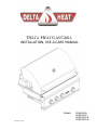
Delta Heat DHBQ26G-B Operating instructions
- Category
- Barbecues & grills
- Type
- Operating instructions

P/N: 18617N (01/14)
Models: DHBQ26G-B
DHBQ32G-B
DHBQ32R/S-B
DHBQ38R/S-B
DELTA HEAT GAS GRILL
INSTALLATION, USE & CARE MANUAL

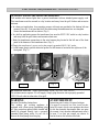
A special message…
Congratulations on your purchase of Delta Heat gas barbecue grill. Delta Heat
is committed to making outdoor cooking products you’ll be proud to own for years.
This manual gives you easy to follow instructions for installing, operating and
maintaining your Delta Heat grill. We recommend reading this manual carefully
before your first use to ensure safety, proper care and operation.
Thank you and welcome!
Delta Heat
_____________________________________________________________________
FOR YOUR RECORDS
Please record the following information and refer to them when contacting the
company or an authorized service agent. This information is found on the data
nameplate, located on the rear panel of the grill. A second label with model number
and serial number is located under the right side of the control panel.
Model #: ________________________________
Serial #: _________________________________
Date of Purchase: __________________________
Place of Purchase: __________________________
Type of Gas: NG LP

IMPORTANT SAFETY INFORMATION – DELTA HEAT GAS GRILL
WARNING! Read this manual carefully and completely before using your grill to ensure proper
operation, proper installation, proper servicing and to reduce the risk of fire, burn hazard and/ or
other injury.
F O R Y O U R S A F E T Y
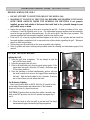
If you smell gas:
1. Shut off gas to the appliance.
2. Extinguish any open flames.
3. Open lid.
4. If odor continues, keep away from the
appliance and immediately call your gas
supplier or fire department.
A V E R T I S S E M E N T
S’il y a une odeur de gaz:
1. Coupez l’admission de gaz de l’appariel.
2. Éteindre toute flamme nue.
3. Ouvrir le couvercle.
4. Si l’odeur continue, évite l’appareil et
appelle tout de suite votre fournisseur de gaz
ou les pompiers.
F O R Y O U R S A F E T Y
1. Do not store or use gasoline or other
flammable vapors and liquids in the
vicinity of this or any other appliance.
2. An LP cylinder not connected for use
shall not be stored in the vicinity of this
or any other appliance.
A V E R T I S S E M E N T
1. Ne pas entreposer ni utiliser de l’essence ni
d’autres vapeurs ou liquides inflammables
dans le voisinage de l’appareil, ni de tout
autre appareil.
2. Une bouteille de propane qui n’est pas
raccordée en vue de son utilisation, ne doit
pas être entreposée dans le voisinage de cet
appareil ou de tout autre appareil.
THIS GRILL IS FOR OUTDOOR USE ONLY:
If stored indoors, detach and leave L.P. cylinder
outdoors.
CE GRIL EST POUR UTILISATION à
L’ExTéRIEUR SEULEMENT:
Si l’appareil est entreposé à l’interieur, enlever
les bouteilles et les laisser à l’extérieur.
B E F O R E L I G H T I N G
1. Read instructions before lighting.
2. Open lid during lighting.
3. If ignition does not occur in 4 seconds,
turn the burner control(s) off, wait 5
minutes, and repeat the lighting
procedure.
A V A N T D ’ A L L U M E R
L ’ A P P A R E I L
1. Lisez les instructions avant d’allumer
l’appareil.
2. Ouvrez le couvercle avant d’allumer l’appareil.
3. Si l’appareil ne s’allume pas en 4 secondes,
fermez le robinet du brûleur, attendez 5
minutes, et procédez de nouveau à l’allumage.

GENERAL SAFETY REQUIREMENTS:
1. The installation of this appliance must conform with local codes or, in the absence of local codes;
either the National Fuel Gas Code, ANZI Z223.1/NFPA 54, or the CAN/CGA-B149.1, Natural
Gas Installation Code or CAN/CGA-B149.2, Propane Installation Code.
2. This outdoor cooking gas appliance is not intended to be installed in or on recreational vehicles
and /or boats.
3. This outdoor cooking gas appliance is intended for use outdoors and shall not be used in a
building, garage or any other enclosed area.
4. Minimum clearance of 12 inches from the back and sides of the grill to adjacent
combustible construction must be maintained. This outdoor cooking gas appliance shall not
be located under overhead-unprotected combustible construction.
5. The utilization of an external electrical source requires that when installed, this outdoor cooking
gas appliance must be electrically grounded in accordance with the local codes or, in the absence
of local codes, with the National Electrical Code, ANSI/NFPA 70, or the Canadian Electrical
Code, CSA C22.1. Keep any electrical supply cord, or the rotisserie motor cord and the fuel
supply hose away from any heated surfaces.
6. Keep your grill in an area clear and free from combustible materials, gasoline and other
flammable vapors and liquids.
7. DO NOT obstruct the flow of combustion and ventilation air to this appliance. Keep the
ventilation openings of the cylinder enclosure free and clear from debris.
8. Check all gas connections for leaks with soapy water solution and brush. Never use an open
flame. (Reference page 8 for leak test procedure).
9. Check flexible hoses for cuts and wear that may affect the safety before each use.
10. Never use charcoal in the grill.
11. Never use the grill in a windy area.
12. Never use the grill without the drip pan installed and push all the way to the back of the grill.
Without the drip pan, hot grease and debris could leak downward and produce a fire hazard.
13. The pressure regulator and hose assembly supplied with the Delta Heat Gas Grill must be used.
Replacement pressure regulators and hose assemblies must be those specified by Delta Heat.
14. CALIFORNIA PROPOSITION 65-WARNING: The burning of gas cooking fuel generates some
by-products which are on the list of substances known by the State of California to cause cancer
or reproductive harm. California law requires businesses to warn customers of potential exposure
to such substances. To minimize exposure to these substances always operate this unit according
to the use and care manual, ensuring you provide good ventilation when cooking with gas.
In Massachusetts: All gas products must be installed using a “Massachusetts” licensed plumber or
gasfitter. A “T” handle type manual gas valve must be installed in the gas supply line to this
appliance. This applies to permanently installed Natural Gas and propane installations. This does
not apply to propane portable installations using a 20 pound tank.

TABLE OF CONTENTS – DELTA HEAT GAS GRILL
GETTING STARTED…………………………………………………………………… ….. 2
GAS REQUIREMENTS
o GAS SAFETY REQUIREMENT……………………………………………... 4
o LP GAS HOOKUP………….………………………………………………… 5
o PORTABLE LP CONNECTION………….………………………………….. 6
o NATURAL GAS INSTALLATION………………………………………….. 7
o LEAK TEST…………………………………………………………………… 8
ELECTRICAL REQUIREMENTS …………………………………………………..……… 9
WIRING DIAGRAM…………………………………………………………………..……..… 10
LOCATING THE GRILL
o CLEARANCE TO COMBUSTIBLE CONSTRUCTION……………………... 11
o CLEARANCE TO NONCOMBUSTIBLE CONSTRUCTION……………..… 11
CUTOUT DIMENSIONS
o GRILL………………………………………………………………………….. 12
ASSEMBLY INSTRUCTIONS
o BRIQUETTE TRAY…………………..……………………………………….. 13
o WARMING RACK…………………………………………………………… 13
o ROTISSERIE…………………………...……………………………………… 14
o BATTERY LOCATION ………………………………………………………. 14
OPERATING INSTRUCTIONS
o BEFORE LIGHTING THE GRILL…………………………………………… 15
o TO LIGHT THE GRILL BURNER ………………………………………….. 15
o MATCH LIGHTING INSTRUCTIONS ……..……………………………… 16
o USING THE GRILL …………………………………………………………… 16
o INTERIOR LIGHT OPERATION AND LIGHT BULB REPLACEMENT……. 16
o USING THE ROTISSERIE BURNER……………..…………………………….. 17
o SEAR ZONE BURNER …………………………....…………………………..… 17
CLEANING AND MAINTENANCE
o STAINLESS STEEL…………………………………………………………… 18
o COOKING GRATES ………………………………………………………… 18
o CERAMIC BRIQUETTE TRAY….…………………………….………….… 18
o U-BURNER & SEAR ZONE BURNER……………………………………… 19
o DRIP PAN ………………….………………………………………………… 19
o SPIDER AND INSECT WARNING…………………………………………… 19
TROUBLE SHOOTING GUIDE…………………...………………………………………… 20
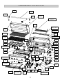
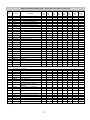
REPLACEMENT PARTS
o EXPLODED VIEW………………………………………….…………………. 21
o REPLACEMENT PARTS LIST…………………………..……………….……. 22
o LIMITED PRODUCT WARRANTY………………………………………...…. 24
o WARRANTY REGISTRATION CARD ………………………………………. 25

GETTING STARTED – DELTA HEAT GAS GRILL
1. Remove all packaging materials, labels and protective plastic film. DO NOT LEAVE UNIT
UNDER THE SUN WITH PROTECTIVE PLASTIC FILM ON FOR A LONG PERIOD OF
TIME AS IT WILL BECOME DIFFICULT TO REMOVE THE FILM.
2. Check to ensure that all grill accessories listed below are included.
Grill Accessories
DHBQ
26G-B
DHBQ
32G-B
DHBQ
32R/S-B
DHBQ
38R/S-B
Grate, Stainless Steel
2
3
3
3
Briquette Tray Assy. (Standard Grill)
2
3
3 / 2
3 / 2
Rotisserie Motor with bracket (s/s)
1
1
Regulator, NG (NG Grills Only)
1
1
1
1
Regulator, LP (LP Grill ONLY)
(1)
(1)
(1)
(1)
Warming Rack, (s/s)
1
1
1
1
Spit Rod, (s/s)
1
1
Meat Holder Forks (pair) (s/s)
1
1
3. Assemble parts as per assembly instructions on page 13-14.
4. Fill out the Warranty Registration Card and mail it to the indicated address.

GETTING STARTED – DELTA HEAT GAS GRILL
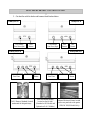
5. Get familiar with the knobs and burners identification below.
Grill U-Burner (Standard) located
underneath the briquette trays.
Sear Zone Burner usually
located on the left side.
(Standard on RS Models and
Optional on R & G Models)
Infrared Rotisserie Burner located
on the rear panel above the grates.
(32R/S & 38R/S Models Only)
Grill
Burner
Grill Burner
Sear Zone (Opt)
Grill
Burner
Grill Burner
Sear Zone (Opt)
Grill
Burner
DHBQ26G-B
DHBQ32G-B
Rotisserie
DHBQ32R/S-B
2
Grill
Burner
Grill Burner /
Sear Zone
DHBQ38R/S-B
Rotisserie
Grill
Burner
Grill Burner /
Sear Zone

GAS SAFETY REQUIREMENTS – DELTA HEAT GAS GRILL
Each appliance is set and tested at the factory for the type of gas supply to be used. Identify
the type of gas, either Natural Gas or LP gas and make sure that the marking on the data plate
(rating plate) matches the gas being supplied to the grill. The data plate is located on the rear panel
of the grill. A second label with model number and serial number is located under the right side of
the control panel.
All gas connections should be made by a qualified technician and in accordance with local
codes and ordinances. The installation must conform with local codes or, in the absence of local
codes, with either the national Fuel Gas Code, ANSI Z223.1/NFPA 54, or CAN/CGA-B149.1,
Natural Gas Installation Code or CAN/CGA-B149.2, Propane Installation Code.
WARNING:
CHECK TO ENSURE THAT THE GAS SUPPLY HOSE DOES NOT COME IN
CONTACT WITH ANY HOT SURFACE OF THE GRILL.
NEVER CONNECT THE GRILL TO AN UNREGULATED GAS SUPPLY.
L.P. GAS (LIQUIFIED PETROLEUM /PROPANE)
If your grill is factory built for L.P., the regulator supplied is set for 11” water column and
is for use with L.P. gas only. The factory-supplied regulator and hose must be used with a 20 lb.
L.P. cylinder.
L.P. GAS SAFETY REQUIREMENT
The LP-gas supply cylinder must be constructed and marked in accordance with the
Specifications for LP-gas Cylinders of the U.S. Department of Transportation (D.O.T.) or the
National Standards of Canada CAN/CSA-B339, Cylinders, Spheres and Tubes for the
Transportation of Dangerous Goods, and Commission, as applicable; and
1. Provided with a listed overfilling prevention device.
2. Provided with a cylinder connection device compatible with the connection for outdoor
cooking appliances.
It must be provided with a shut-off valve terminating in gas tank valve outlet. It must include a
collar to protect the cylinder valve. The cylinder supply system must be arranged for vapor
withdrawal.
Do not operate the gas grill indoors or in any enclosed area. If the gas grill is not in use, the gas
must be turned off at the supply cylinder. If the grill is to be stored indoors, disconnect the gas
supply cylinder and leave the cylinder outdoors.
3
4
3

LP GAS HOOK-UP – DELTA HEAT GAS GRILL
Install the factory-supplied hose and regulator assembly as shown. Connect the
3
/
8
” flare end of the hose
to the grill coupling using a ¾” open wrench. Do not apply pipe sealant to the
3
/
8
” flare connection. Connect the
regulator to the LP cylinder hand tighten it, do not use a wrench. Check for leaks using soapy water solution.
(Reference page 8 for leak test procedure).
Note: An enclosure for LP gas cylinder must be vented on the level of the cylinder valve and at floor
level. The effectiveness of the opening(s) for purposes of ventilation shall be determined with the LP gas
supply cylinder in place. This shall be accomplished by one of the following:
a. One side of the enclosure shall be fully open; or
b. For an enclosure having four sides, a top and a bottom:
1. At least two ventilation openings at cylinder valve level shall be provided in the sidewall,
equally sized, spaced at 180 degrees (3.14 rad), and unobstructed. Each opening shall have a
total free area of not less than 1/2 square inch per pound (7.1 cm
2
/kg) of stored fuel capacity
and not less than a total free area of 10 square inches (64.5 cm
2
).
Ventilation opening(s) shall be provided at floor level and shall have a total free area of not less
than ½" square inch per pound (7.1 cm2/kg) of stored fuel capacity and not less than a total free area of
10 square inches (64.5 cm2). If ventilation openings at floor level are in a sidewall, there shall be at
least two openings. The bottom of the openings shall be at floor level and the upper edge no more than 5
inches (127 mm) above the floor. The openings shall be equally sized, spaced at 180 degrees (3.14 rad)
and unobstructed.
5

PORTABLE LP CONNECTION – DELTA HEAT GAS GRILL
NOTE: USE ONLY A 20-LBS. (5-GALLON
CAPACITY) GAS CYLINDER.
WARNING: DO NOT PLACE MORE THAN ONE
CYLINDER IN THE BASE CABINET ENCLOSURE
AT ANY TIME.
WARNING: DO NOT USE A DENTED OR RUSTED
LP CYLINDER.
NEVER USE A CYLINDER WITH A DAMAGED
VALVE.
ALWAYS CHECK FOR LEAKS AFTER
CHANGING THE LP CYLINDER. (Page 8)
THE LP PRESSURE REGULATOR AND HOSE
SUPPLIED WITH THIS UNIT MUST BE USED
WITHOUT ALTERATION.
ALWAYS USE THE TANK SECURING DEVICE
SUPPLIED WITH GRILL BASE.
1) To install the gas cylinder, place the cylinder onto the provided cutout.
2) Check to ensure that the tank’s gas valve on top of the cylinder is closed.
3) Connect the LP regulator (included) to the cylinder and hand-tighten only. Open the
tank valve and make sure all connections are leak tight using a soapy water solution
and a brush. (Reference page 8 for leak test procedure).
6

NATURAL GAS INSTALLATION – DELTA HEAT GAS GRILL
The installation must conform with local codes or, in the absence of local codes, with either the
national Fuel Gas Code, ANSI Z223.1/NFPA 54, or CAN/CGA-B149.1, Natural Gas Installation Code or
CAN/CGA-B149.2, Propane Installation Code.
1. This gas appliance and its individual shutoff valve must be disconnected from the gas supply piping
system during any pressure testing of that system at the test pressures in excess of 1/2 psi (3.5 kPa).
2. This appliance must be isolated from the gas supply piping system by closing its individual manual
shutoff valve during any pressure testing of the gas supply piping system at test pressures equal to or
less than 1/2 psi (3.5 kPa).
If the gas grill is factory built for Natural Gas, the regulator supplied is set for 4” water column.
The regulator is convertible to 10” water column for plumb-in system LP application. Do not use with a
20-lb LP cylinder. Make sure that the regulator is set for the correct gas type. To check, remove the brass
hex cap. You will find the conversion plastic pin attached to the cap to the underside of the cap. If the disc
(1/2 in. diameter) of the pin is close to the cap, then the regulator is set for Natural Gas. If the disc is at the
tip of the pin, away from the brass cap, the regulator is set for system LP application. To convert to
Natural Gas, remove the plastic conversion pin and invert and replace it back in a manner such that the
disc is close to the brass cap. For both Natural and LP, the maximum inlet pressure is 14” water column.
A typical Natural Gas installation is shown below. Make sure that the factory-supplied regulator is
used and installed with the arrow mark on the regulator pointing towards the gas grill. Do not use any
replacement regulator other than that specified by DELTA HEAT. Use only pipe sealants that are
approved for use with Natural and LP gases. An installer-supplied gas shutoff valve must be installed in
an accessible location.
7

LEAK TEST – DELTA HEAT GAS GRILL
CAUTION BEFORE TESTING
Finding and/or fixing a gas leak is NOT a “DO-IT-YOURSELF” procedure.
NEVER USE THE GRILL WITHOUT FIRST LEAK TESTING THE GAS CONNECTIONS.
WARNING: DO NOT USE OPEN FLAME TO CHECK FOR LEAKS. USE OF AN OPEN FLAME
COULD RESULT IN A FIRE, EXPLOSION, BODILY HARM OR DEATH.
DO NOT SMOKE WHILE PERFORMING THE LEAK TEST!
To prevent fire or explosion hazard, DO NOT use or permit sources of ignition in the area while
performing a leak test. Perform leak test outdoors only.
Check to ensure that flexible hoses do not have any cuts and wear that may affect the safety before
each use. Only the factory supplied hose and regulator must be used. Use only replacement regulator
and hose assemblies specified by DELTA HEAT.
LEAK TEST
1) Prepare a leak testing solution of sudsy water by mixing in a spray bottle with half liquid soap and half
water.
2) Confirm that all control knobs are in the OFF position.
3) Turn the main gas valve supply ON.
4) Apply leak testing solution by spraying on the pipe joints, fittings, and hose.
5) A gas leak is detected if;
a) there is a faint gas smell and/or…
b) …growing bubbles appear on any of the connection points and/or hose, DO NOT attempt to ignite
the grill and IMMEDIATELY turn off the gas supply valve.
6) When there is a gas leak, call a qualified service technician. DO NOT use the grill until the leak is
corrected.
8

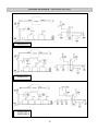
ELECTRICAL REQUIREMENTS – DELTA HEAT GAS GRILL
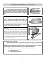
TO INSTALL AND SECURE POWER TRANSFORMER
Grill models with interior lights have a power transformer with an attached power supply cord.
This transformer must be secured in a dry location and away from the grill firebox and excessive
heat area.
a. In a base cart application, four mounting screws with nuts are provided at the bottom left rear
corner of the cart. If not provided, drill four holes using the transformer box as a template.
Secure the transformer box as shown. (Fig. 1)
b. In a built-in application secure the transformer box near the GFCI 120V outlet in a dry location
and away from the grill firebox and excessive heat area.
c. Make the transformer connections to the wire harness plug located at the left rear of the front
panel to the harness of the transformer box. (Fig. 2)
d. Plug-in the transformer’s power cord to the properly grounded GFCI 120V outlet.
e. A side burner plug to provide electrical power for side burner is located at the right rear of the
front panel. (Fig. 3)
AVERTISSEMENT
Instruction pour la mise à la terre electrique:
Cet appareil est muni d’une fiche à trois broches
(mise à la terre) afin de vous protéger des chocs
et doit être branché directement dans une prise
de courant à trois broches adéquatement mise à
la terre. Il ne faut pas couper ou enlever la
broche de mise à la terre de cette fiche.
WARNING
Electrical Grounding Instructions:
This outdoor gas cooking appliance is
equipped with a three prong (grounding) plug
for your protection against shock hazard and
should be plugged directly into a properly
grounded three prong outlet. Do not cut or
remove the third prong from this plug.
Fig. 1
ROTISSERIE MOTOR: (Motor Specification: 40 lbs. / in; 0.5A; 15W; 60 Hz.)
The rotisserie motor requires 120 volt supply. Simply plug the motor into a properly grounded
GFCI 120 volt outlet at either side of the grill.
9
Fig. 2
Fig. 3

WIRING DIAGRAM – DELTA HEAT GAS GRILL
DHBQ32G-B
DHBQ32R/S-B
DHBQ38R/S-B
10
DHBQ26G-B

LOCATING THE GRILL – DELTA HEAT GAS GRILL
CLEARANCE TO COMBUSTIBLE CONSTRUCTION
A minimum clearance of 12” from the sides and 12” from the back of the grill to adjacent vertical
combustible construction must be maintained.
DÉGAGEMENT DE TOUTE CONSTRUCTION COMBUSTIBLE
Il faut maintenir une distance minimum de 12 po (30.48 cm) sur les côtés et de 12 po (30.48 cm) sur
l’arrière du gril par rapport aux constructions combustibles verticales adjacentes.
CLEARANCE TO NONCOMBUSTIBLE CONSTRUCTION
A minimum clearance of 3” from the back of the grill above cooking surface to non-combustible
construction is required to allow the grill hood to open completely.
A minimum of 6” clearance to the sides of the grill above cooking surface to non-combustible
construction is recommended to provide space for the rotisserie motor and the spit rod. The grill can
be installed directly next to non-combustible construction below the cooking surface.
DÉGAGEMENT DE TOUTE CONSTRUCTION INCOMBUSTIBLE
Une distance minimum de 3 po (7.62 cm) de l’arrière du gril au-dessus de toute surface de cuisson à
la construction incombustible est prescrite pour permettre à la hotte d’ouvrir complètement. Une
distance minimum de 6 po (15.24 cm) des côtés du gril au-dessus de la surface de cuisson à la
construction incombustible est recommandée pour prévoir de l’espace pour le moteur de la rôtissoire
et la poignée des broches de cuisson. Le gril peut être installé directement à proximité d’une
construction incombustible en-dessous de la surface de cuisson.
This gas appliance is designed and certified for outdoor use only. Do not locate this grill under
overhead combustible surfaces. Do not operate the grill inside a building, garage, recreation vehicle
or any enclosed area. When choosing an area, consider exposure to wind, proximity to traffic paths
and length of gas supply line. Keep gas supply lines as short as possible to reduce pressure drop.
Keep the grill away from windy area but keep the grill in a well-ventilated area. Do not obstruct the
flow of combustion and ventilation air around the grill. The supporting edges of the grill must be
located level and flat. The counter should also be leveled.
11

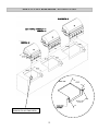
GRILL CUT-OUT DIMENSIONS – DELTA HEAT GAS GRILL
12
SEE DETAIL
(TYPICAL TO ALL TOP UNITS)
DETAIL
19 3/4
WIDTH OF UNIT
(26, 32, 38)
(AS SHOWN) DHBQ32R/S-B
DHBQ32G-B
DHBQ38R/S-B
DHBQ26G-B

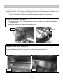
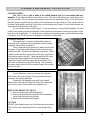
ASSEMBLY INSTRUCTIONS – DELTA HEAT GAS GRILL
The DELTA HEAT Grill is produced fully assembled and tested in the factory and requires no major
assembly in the field. For the purpose of safe shipping and transit, some parts such as the briquette trays
and rotisserie components are wrapped inside the grill and require minor assembly.
Check to ensure that all packaging material have been removed prior to grill operation.
TO INSTALL BRIQUETTES TRAYS
1. Put briquette trays into the grill above the burner as shown by lining up the tab with the channel of
the briquette tray.
2. Then put the stainless steel grates over the briquette trays.
WARMING RACK LEVEL POSITIONS:
The warming rack may be used to keep food warm and avoid overcooking the food. To install the
warming rack, use the hook to latch on at the rear hood panel as shown below (Fig. 3)
When the warming rack is not in use, it should be installed in a stow-away position (Fig. 4).
13
Fig. 3
Fig. 4
CHANNEL
TAB

ASSEMBLY INSTRUCTIONS – DELTA HEAT GAS GRILL
ROTISSERIE ASSEMBLY
BATTERY LOCATION
For Larger Loads
1. Install the rotisserie motor horizontally as shown. The
motor socket hole will line up with the front notch of the
saddles.
2. Insert the rotisserie rod into the motor socket hole and place
the rod on the front notch of each saddle.
3. Remove the stainless steel grates.
4. Place a basting pan on top of the briquette trays to catch the
drippings. (basting pan not supplied)
For Smaller Loads
1. Install the rotisserie motor horizontally as shown. The
motor socket hole will line up with the rear notch of the
saddles.
2. Insert the rotisserie rod into the motor socket hole and
place the rod on the rear notch of each saddle.
3. Place a basting pan on top of the stainless steel grates to
catch the drippings (basting pan not supplied)
4.
14
INSTALL THE BATTERY
AS SHOWN

OPERATING INSTRUCTIONS – DELTA HEAT GAS GRILL
BEFORE LIGHTING THE GRILL
DO NOT ATTEMPT TO LIGHT THE GRILL IF YOU SMELL GAS.
WARNING! IT IS CRITICAL THAT THE GAS BURNERS ARE PROPERLY INSTALLED
WITH THEIR ORIFICES INSIDE THE BURNERS AIR SHUTTERS. If not properly
installed, gas may leak outside of the burner that could lead to fire, potential damage to your
grill, bodily injury or death.
Inspect the gas supply piping or hose prior to turning the gas ON. If there is evidence of cuts, wear,
or abrasion, it must be replaced prior to use. The replacement pressure regulator and hose assembly
must be the type specified by the manufacturer. Do not use the grill if the odor of gas is present. The
pressure regulator and hose assembly supplied with the units must be used.
If the unit is LP, screw the regulator and hand tighten to the valve of the cylinder and leak check the
hose and regulator connections with a soap and water solution before operating the grill. Reference
page 8 for leak test procedure.
Always keep your face and body as far away as possible when lighting.
Refer to spiders and insects warning and procedure under the cleaning and maintenance page of this
manual.
TO LIGHT THE GRILL BURNER
Lighting the Grill
1. Open the grill hood completely. Do not attempt to light the
grill with the hood closed.
2. Open the gas supply shut-off valve.
3. Push in the knob and verify that the spark igniter sparks. If the
igniter does not spark, check the 9V battery. (Reference page
14 for battery location).
4. Once the sparking is verified simultaneously push-in and turn
the knob counter-clock-wise to the biggest flame marking on
the knob. Hold the knob pushed in for 4 seconds. Once you
see or hear a flame you can release the knob.
For Rotisserie Lighting
Push-in and turn the knob to HIGH. Hold for 30 seconds to heat
up the safety thermocouple and release knob. If the rotisserie
burner will not stay lit, repeat the process.
CAUTION: If ignition does not take place within 4 seconds, turn
knob to the OFF position, wait for five minutes and repeat step 3
and 4.
5. Close the hood to allow the grill to pre-heat until the hood
thermometer displays the desired grilling temperature.
15

OPERATING INSTRUCTIONS – DELTA HEAT GAS GRILL
USING THE GRILL
1. Check to be certain that the drip pan is in place and pushed all the way into the grill.
2. Light the grill burners using the instructions in use and care manual.
3. Turn the control knobs to HI and allow the grill to preheat for 15 minutes or until desired
temperature is displayed on the thermometer. The top cover is to be closed during the appliance
preheat period.
4. Place the food on the grill and cook to the desired temperature doneness. Adjust heat setting, if
necessary. The control knob may be set to any position between HI and LO.
5. Allow grill to cool then you may clean the drip pan after each use.
Match/BBQ Lighter Lighting Instructions:
If there is no electrical power supply available or if spark igniter will
not light the burners, the burners can be lit manually using a
lighted long match, taper or BBQ lighter.
1. Push and turn the knob counter-clock-wise to the biggest flame
marking on the bezel. Hold the knob pushed in for 4 seconds.
2. Using the provided match holder, insert a lit match or BBQ
lighter thru the grates and near the top of the cross tube of the
burner. Once you see or hear a flame you can release the knob.
Important: If burner fails to light within 4 seconds, turn off gas
and wait 5 minutes before repeating the process.
Warning: If you smell gas, shutoff the gas supply and
immediately check for leaks using the soapy water technique.
(See Page 8)
INTERIOR LIGHT OPERATION
The DELTA HEAT grill is equipped with interior halogen lights for late night grilling. The grill is equipped
with a switch that controls the functionality of the interior lights.
1. Push the switch located on the left side of front panel to turn ON interior.
WARNING: Do not touch the interior halogen lights. It may be hot and can cause serious burns.
REPLACING INTERIOR LIGHT BULBS
WARNING! Unplug the grill from the 120V power source before replacing the light bulb.
1. Remove the screw that holds the lens cover and slide the lens cover out.
2. Remove the housing from the grill.
3. Loosen the screws that hold the bulb in the light housing.
4. Remove the old light bulb by pulling it straight out of the socket without twisting the light bulb.
5. Wearing plastic gloves, insert the new light bulb into the socket. DO NOT touch bulb with bare
hands as the oil and dirt will shorten bulb life.
6. Slide the light lens back into the light assembly and screw it in to secure it.
16
Page is loading ...
Page is loading ...
Page is loading ...
Page is loading ...
Page is loading ...
Page is loading ...
Page is loading ...
Page is loading ...
Page is loading ...
Page is loading ...
-
 1
1
-
 2
2
-
 3
3
-
 4
4
-
 5
5
-
 6
6
-
 7
7
-
 8
8
-
 9
9
-
 10
10
-
 11
11
-
 12
12
-
 13
13
-
 14
14
-
 15
15
-
 16
16
-
 17
17
-
 18
18
-
 19
19
-
 20
20
-
 21
21
-
 22
22
-
 23
23
-
 24
24
-
 25
25
-
 26
26
-
 27
27
-
 28
28
-
 29
29
-
 30
30


Delta Heat DHBQ26G-B Operating instructions
- Category
- Barbecues & grills
- Type
- Operating instructions
Ask a question and I''ll find the answer in the document
Finding information in a document is now easier with AI
in other languages
- français: Delta Heat DHBQ26G-B Mode d'emploi
Other documents
-
 APEC Water Systems UVBULB-SS Operating instructions
-
Prestige GBQRP36L Operating instructions
-
RCS RSB3A Pro Burner Owner's manual
-
-
Twin Eagles TEBQ42R-B Owner's manual
-
-
-
 Frontgate 720-0170 Owner's manual
-
-
Alfresco AGBQ-30 Owner's manual

