Page is loading ...

© 2000 McQuay International
MicroTech II™
Applied Rooftop Unit Controller
Space Comfort Control (SCC)
• Used with McQuay models: RPS, RFS, RCS, RPR, RFR, RDT, RDS,
RAR and RAH
Operation Manual OM 138
Group:
Applied Systems
Part Number:
OM138
Date:
April 2001
Discharge Cooling
Disch Air= 55.0°F
Clg Capacity= 50%
Eff Clg Spt= 55°F

2
Contents
Introduction . . . . . . . . . . . . . . . . . . . . . . . . . . . . . . . 4
Getting Started . . . . . . . . . . . . . . . . . . . . . . . . . . . . . 6
Using the Keypad/Display . . . . . . . . . . . . . . . . . . . . . . . . . . . . . . . . 6
Menu Structure . . . . . . . . . . . . . . . . . . . . . . . . . . . . . . . . . . . . 6
Display Format. . . . . . . . . . . . . . . . . . . . . . . . . . . . . . . . . . . . 10
Password Protection . . . . . . . . . . . . . . . . . . . . . . . . . . . . . . . 10
Keypad Functions . . . . . . . . . . . . . . . . . . . . . . . . . . . . . . . . . 11
Keypad/Display Exercises . . . . . . . . . . . . . . . . . . . . . . . . . . . 11
Keypad/Display Menu Reference . . . . . . . . . . . . . . . . . . . . . . . . . 13
System Summary . . . . . . . . . . . . . . . . . . . . . . . . . . . . . . . . . 13
Airflow . . . . . . . . . . . . . . . . . . . . . . . . . . . . . . . . . . . . . . . . . . 16
Temperature . . . . . . . . . . . . . . . . . . . . . . . . . . . . . . . . . . . . . 17
Humidity. . . . . . . . . . . . . . . . . . . . . . . . . . . . . . . . . . . . . . . . . 23
Schedules . . . . . . . . . . . . . . . . . . . . . . . . . . . . . . . . . . . . . . . 24
Setup/Service . . . . . . . . . . . . . . . . . . . . . . . . . . . . . . . . . . . . 26
Active Alarms. . . . . . . . . . . . . . . . . . . . . . . . . . . . . . . . . . . . . 38
Previous Alarms. . . . . . . . . . . . . . . . . . . . . . . . . . . . . . . . . . . 42
Operator’s Guide . . . . . . . . . . . . . . . . . . . . . . . . . . 43
Determining Unit Status. . . . . . . . . . . . . . . . . . . . . . . . . . . . . . . . . 43
UnitStatus . . . . . . . . . . . . . . . . . . . . . . . . . . . . . . . . . . . . . . . 43
Clg Capacity . . . . . . . . . . . . . . . . . . . . . . . . . . . . . . . . . . . . . 43
Htg Capacity . . . . . . . . . . . . . . . . . . . . . . . . . . . . . . . . . . . . . 43
Clg Status . . . . . . . . . . . . . . . . . . . . . . . . . . . . . . . . . . . . . . . 43
Htg Status . . . . . . . . . . . . . . . . . . . . . . . . . . . . . . . . . . . . . . . 44
Auto/Manual Operation . . . . . . . . . . . . . . . . . . . . . . . . . . . . . . . . . 45
Ctrl Mode . . . . . . . . . . . . . . . . . . . . . . . . . . . . . . . . . . . . . . . . 45
Appl Mode . . . . . . . . . . . . . . . . . . . . . . . . . . . . . . . . . . . . . . . 45
Occupancy. . . . . . . . . . . . . . . . . . . . . . . . . . . . . . . . . . . . . . . 46
Occ Mode . . . . . . . . . . . . . . . . . . . . . . . . . . . . . . . . . . . . . . . 46
Occ Src . . . . . . . . . . . . . . . . . . . . . . . . . . . . . . . . . . . . . . . . . 47
Bypass Time (Tenant Override). . . . . . . . . . . . . . . . . . . . . . . 48
Emergency Override . . . . . . . . . . . . . . . . . . . . . . . . . . . . . . . 48
Scheduling . . . . . . . . . . . . . . . . . . . . . . . . . . . . . . . . . . . . . . . . . . . 48
Setting Controller Date and Time . . . . . . . . . . . . . . . . . . . . . 49
Internal Daily Scheduling . . . . . . . . . . . . . . . . . . . . . . . . . . . . 49
Holiday Scheduling . . . . . . . . . . . . . . . . . . . . . . . . . . . . . . . . 49
One Event Scheduling . . . . . . . . . . . . . . . . . . . . . . . . . . . . . . 49
Optimal Start . . . . . . . . . . . . . . . . . . . . . . . . . . . . . . . . . . . . . 50
External Time Scheduling . . . . . . . . . . . . . . . . . . . . . . . . . . . 51
Network Time Scheduling . . . . . . . . . . . . . . . . . . . . . . . . . . . 51
Alarm Monitoring . . . . . . . . . . . . . . . . . . . . . . . . . . . . . . . . . . . . . . 51
About Alarms . . . . . . . . . . . . . . . . . . . . . . . . . . . . . . . . . . . . . 51
Remote Alarm Indication . . . . . . . . . . . . . . . . . . . . . . . . . . . . 52
Local Alarm Indication (Keypad/Display) . . . . . . . . . . . . . . . . 53
Remote Alarm Clearing . . . . . . . . . . . . . . . . . . . . . . . . . . . . . 54
Configuring Remote Alarm Output. . . . . . . . . . . . . . . . . . . . . 54
Setting Alarm Limits. . . . . . . . . . . . . . . . . . . . . . . . . . . . . . . . 56
Unit Configuration/Service Parameters . . . . . . . . . . . . . . . . . . . . . 56
Calibrate Mode . . . . . . . . . . . . . . . . . . . . . . . . . . . . . . . . . . . 56
Zone (Space) Temperature Sensor . . . . . . . . . . . . . . . . . . . . 56
Miscellaneous Service Parameters . . . . . . . . . . . . . . . . . . . . 57
Control Timer Settings. . . . . . . . . . . . . . . . . . . . . . . . . . . . . . 58
Manual Output Control. . . . . . . . . . . . . . . . . . . . . . . . . . . . . . 59
Description of Operation . . . . . . . . . . . . . . . . . . . . 61
Operating States and Sequences . . . . . . . . . . . . . . . . . . . . . . . . . 61
About Operating States . . . . . . . . . . . . . . . . . . . . . . . . . . . . . 61
Operating State Descriptions . . . . . . . . . . . . . . . . . . . . . . . . . 61
Operating State Sequence Chart. . . . . . . . . . . . . . . . . . . . . . 64
Startup Control. . . . . . . . . . . . . . . . . . . . . . . . . . . . . . . . . . . . . . . . 64
Before Startup . . . . . . . . . . . . . . . . . . . . . . . . . . . . . . . . . . . . 64
Fan Startup . . . . . . . . . . . . . . . . . . . . . . . . . . . . . . . . . . . . . . 65
Heat/Cool Changeover . . . . . . . . . . . . . . . . . . . . . . . . . . . . . . . . . 65
Temperature Control . . . . . . . . . . . . . . . . . . . . . . . . . . . . . . . 66
0-30% Outdoor Air Damper Control . . . . . . . . . . . . . . . . . . . . . . . . 68
Minimum Ventilation Control . . . . . . . . . . . . . . . . . . . . . . . . . 68
100% Outdoor Air Damper Control. . . . . . . . . . . . . . . . . . . . . . . . . 68
Economizer . . . . . . . . . . . . . . . . . . . . . . . . . . . . . . . . . . . . . . . . . . 68
Temperature Control . . . . . . . . . . . . . . . . . . . . . . . . . . . . . . . 68
Economizer Changeover Method. . . . . . . . . . . . . . . . . . . . . . 69
Minimum Ventilation Control . . . . . . . . . . . . . . . . . . . . . . . . . 70
Cooling: Multistage. . . . . . . . . . . . . . . . . . . . . . . . . . . . . . . . . . . . . 72
Temperature Control . . . . . . . . . . . . . . . . . . . . . . . . . . . . . . . 72
Low Ambient Cooling Lockout . . . . . . . . . . . . . . . . . . . . . . . . 73
Compressor Staging. . . . . . . . . . . . . . . . . . . . . . . . . . . . . . . . 73
Condenser Fan Control . . . . . . . . . . . . . . . . . . . . . . . . . . . . . 76
Circuit Pumpdown . . . . . . . . . . . . . . . . . . . . . . . . . . . . . . . . . 76
Cooling: Modulating . . . . . . . . . . . . . . . . . . . . . . . . . . . . . . . . . . . . 77
Temperature Control . . . . . . . . . . . . . . . . . . . . . . . . . . . . . . . 77
Heating: Multistage. . . . . . . . . . . . . . . . . . . . . . . . . . . . . . . . . . . . . 78
Temperature Control . . . . . . . . . . . . . . . . . . . . . . . . . . . . . . . 78
Morning Warm-up Control . . . . . . . . . . . . . . . . . . . . . . . . . . . 79
High Ambient Heating Lockout. . . . . . . . . . . . . . . . . . . . . . . . 79
Discharge Air Low Limit Control . . . . . . . . . . . . . . . . . . . . . . . 80
Heating: Modulating . . . . . . . . . . . . . . . . . . . . . . . . . . . . . . . . . . . . 80
Temperature Control . . . . . . . . . . . . . . . . . . . . . . . . . . . . . . . 80
Morning Warm-up Control . . . . . . . . . . . . . . . . . . . . . . . . . . . 83
High Ambient Heating Lockout. . . . . . . . . . . . . . . . . . . . . . . . 84
Discharge Air Low Limit Control . . . . . . . . . . . . . . . . . . . . . . . 84
Dehumidification. . . . . . . . . . . . . . . . . . . . . . . . . . . . . . . . . . . . . . . 85
Enabling Dehumidification . . . . . . . . . . . . . . . . . . . . . . . . . . . 85
Dehumidification Cooling Operation. . . . . . . . . . . . . . . . . . . . 85
Dehumidification Heating Operation. . . . . . . . . . . . . . . . . . . . 86
Energy Recovery . . . . . . . . . . . . . . . . . . . . . . . . . . . . . . . . . . . . . . 86
Enthalpy Wheel Control . . . . . . . . . . . . . . . . . . . . . . . . . . . . . 86
Exhaust Fan Control. . . . . . . . . . . . . . . . . . . . . . . . . . . . . . . . 87
Energy Recovery Bypass Damper Control. . . . . . . . . . . . . . . 88
Return Fan Capacity Control . . . . . . . . . . . . . . . . . . . . . . . . . . . . . 88
Direct Building Static Pressure Control . . . . . . . . . . . . . . . . . 88
Return Fan Direct Position Control. . . . . . . . . . . . . . . . . . . . . 89
SAF/RAF Differential OA Reset . . . . . . . . . . . . . . . . . . . . . . . 89
Unoccupied Control . . . . . . . . . . . . . . . . . . . . . . . . . . . . . . . . . . . . 89
Unoccupied Heating (Night Setback) . . . . . . . . . . . . . . . . . . . 89
Unoccupied Cooling (Night Setup) . . . . . . . . . . . . . . . . . . . . . 90
Purge . . . . . . . . . . . . . . . . . . . . . . . . . . . . . . . . . . . . . . . . . . . 90
Alarm Control . . . . . . . . . . . . . . . . . . . . . . . . . . . . . . . . . . . . . . . . . 91
Faults . . . . . . . . . . . . . . . . . . . . . . . . . . . . . . . . . . . . . . . . . . . 91
Problems . . . . . . . . . . . . . . . . . . . . . . . . . . . . . . . . . . . . . . . . 92
Warnings . . . . . . . . . . . . . . . . . . . . . . . . . . . . . . . . . . . . . . . . 97
MicroTech II DDC Features . . . . . . . . . . . . . . . . . . 99
Direct PID Method . . . . . . . . . . . . . . . . . . . . . . . . . . . . . . . . . . . . . 99
Cascaded PID Method . . . . . . . . . . . . . . . . . . . . . . . . . . . . . . . . . . 99
PID Control Parameters . . . . . . . . . . . . . . . . . . . . . . . . . . . . . . . . 100
Period . . . . . . . . . . . . . . . . . . . . . . . . . . . . . . . . . . . . . . . . . . 100
Proportional Band and Integral Time . . . . . . . . . . . . . . . . . . 100
Adjusting PID Control Parameters . . . . . . . . . . . . . . . . . . . . . . . . 100
Correcting System Instability (“Hunting”) . . . . . . . . . . . . . . . 100
Correcting System “Sluggishness” . . . . . . . . . . . . . . . . . . . . 101
Software Identification and Configuration. . . . . 102
Main Control Board (MCB) Configuration. . . . . . . . . . . . . . . . . . . 102
Main Control Board (MCB) Data Archiving. . . . . . . . . . . . . . . . . . 103
Keypad/Display Objects . . . . . . . . . . . . . . . . . . . . . . . . . . . . . . . . 103
Troubleshooting . . . . . . . . . . . . . . . . . . . . . . . . . . 105

OM 138 3
McQuay, MicroTech II, and RoofPak are registered trademarks of McQuay International.
Microsoft is a registered trademark of Microsoft Corporation.
Windows is a trademark of Microsoft Corporation.
Copyright © 2000 McQuay International. All rights reserved throughout the world.
Document Number:
OM 138
Revision: April 2001

4 OM 138
Introduction
This manual provides information regarding the MicroTech
II control system used in the McQuay RoofPak applied roof-
top unit product line. It specifically describes the sequences
of operation and programmable options for units with fac-
tory equipped space comfort control (SCC) software. It also
includes information regarding how to use the keypad/dis-
play to enter and display data.
For information regarding MicroTech II components,
input/output configurations, field wiring options and require-
ments, and service procedures, refer to IM696, MicroTech II
Applied Rooftop Unit Controller. For installation and startup
instructions and general information regarding a particular
rooftop unit, refer to the applicable model-specific installa-
tion and maintenance manual (refer to Table 1).
Table 1: Model-Specific Rooftop Unit Installation
Literature
Rooftop Unit Model
Installation & Maintenance Data
Bulletin Number
RPS (18-40 tons)
IM 157RFS (18-40 tons)
RCS (18-40 tons)
RPS (45-135 tons)
IM 485RFS (45-135 tons)
RCS (45-135 tons)
RDT IM 486
RDS (800 & 802) IM 178
RAH IM 487
NOTICE
This equipment generates, uses, and can radiate radio frequency energy and, if not installed and used in
accordance with this instruction manual, may cause interference to radio communications. It has been tested
and found to comply with the limits for a Class A digital device, pursuant to part 15 of the FCC rules. These
limits are designed to provide reasonable protection against harmful interference when the equipment is
operated in a commercial environment. Operation of this equipment in a residential area is likely to cause
harmful interference in which case the user is required to correct the interference at his own expense.
McQuay International disclaims any liability resulting from any interference or for the correction
thereof.
WARNING
Electric shock hazard. Can cause personal injury or equipment damage.
This equipment must be properly grounded. Connections and service to the MicroTech II control panel must
be performed only by personnel that are knowledgeable in the operation of the equipment being controlled.
WARNING
Excessive moisture in the control panel can cause hazardous working conditions and improper
equipment operation.
When servicing this equipment during rainy weather, the electrical components in the main control panel
must be protected from the rain.

OM 138 5
CAUTION
Extreme temperature hazard. Can cause damage to system components.
The MicroTech II controller is designed to operate in ambient temperatures from -20°F to 125°F. It can be
stored in ambient temperatures from -40°F to 140°F. It is designed to be stored and operated in relative
humidity up to 95% (non-condensing).
CAUTION
Static sensitive components. A static discharge while handling electronic circuit boards can cause
damage to the components.
Discharge any static electrical charge by touching the bare metal inside the main control panel before per-
forming any service work. Never unplug any cables, circuit board terminal blocks, relay modules, or power
plugs while power is applied to the panel.
WARNING
To avoid possible unit damage, Compressor pumpdown is required before removing power to the controller.

6 OM 138
Getting Started
The MicroTech II Applied Rooftop Unit Controller is a self-
contained device that is capable of complete, stand-alone
operation. Information in the controller can be displayed and
modified by using the keypad/display in the unit main con-
trol panel.
The following sections describe how to use the keypad/dis-
play.
Using the Keypad/Display
The keypad/display, shown in Figure 1, is provided with all
MicroTech II Applied Rooftop Unit Controllers on these
units. With the keypad/display, operating conditions, system
alarms, control parameters, and schedules can be monitored.
After password entry, set points, parameters, and schedules
can be edited.
Menu Structure
The keypad accessible information in the MicroTech II con-
troller is organized in a menu structure to provide quick
access. As shown in Figure 2 on page 7, this structure con-
tains 1 main menu and a string of 47 sub-menus. Each sub-
menu is made up of one or more menu items. The string of
47 sub-menus is divided into 8 “categories.” The main menu
has eight items within it that “point” or provide a “book-
mark” to the first sub-menu within the respective category.
The eight categories in the main menu are “System Sum-
mary”, “Airflow”, “Temperature”, “Humidity”, “Schedules”,
“Setup/Service”, “Active Alarms” and “Previous Alarms.”
The name of each category generally describes the basic pur-
pose of the menus in the particular group. Complete infor-
mation regarding the contents of each sub-menu is included
in “Keypad/Display Menu Reference” on page 13.
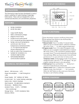
Figure 1: Keypad/display
Discharge Cooling
Disch Air= 55.0°F
Clg Capacity= 50%
Eff Clg Spt= 55°F

OM 138 7
Figure 2: Keypad Accessible Menu Structure
Sub Menus
Keypad Key Definitions
Move Display Left
Move Edit Cursor Left
System Summary
Airflow
Humidity
Schedules
Setup/Service
Active Alarms
Previous Alarms
1
2
3
4
5
6
7
Temperatures
8
System
1 2 3
UnitStatus= _____
4
A
Clg Capacity= xxx%
Htg Capacity= xxx%
Clg Status= _____
Htg Status= _____
Ctrl Mode= Auto
Appl Mode= Heat/Cool
Occupancy
Occupancy= _____
Occ Mode= Auto
Occ Src= _____
Bypass Time= 0min
Emerg Override= Norm
Temperatures
Control Temp= xxx.x°F
Disch Air= xxx.x°F
Return Air= xxx.x°F
Space Temp= xxx.x°F
OA Temp= xxx.x°F
Ent Fan= xxx.x°F
Airflow Summary
Flow Status= _____
Disch Fan= _____
RF/EF Fan= _____
Fan Operation= _____
Bldg Pressure Zone Cooling
Control Temp= xxx.x°F
Clg Capacity= xxx%
Eff Clg Spt= xxx.x°F
Occ Clg Spt= 75.0°F
Clg Deadband= 2.0°F
CtrlTemp Src= Return
Space Temp= xxx.x°F
UnoccClg Spt= 85.0°F
UnoccClgDiff= 3.0°F
Clg Status= _____
OATComp Lock= 55°F
OATLock Diff= 1°F
Bldg Press= x.xx"WC
BldgSP Spt= 0.050"WC
BSP Db= 0.010"WC
RF/EF Fan Cap= xxx%
Discharge Cooling
Disch Air= xxx.x°F
Clg Capacity= xxx%
Eff Clg Spt= xxx.x°F
Clg Db= 1.0°F
Min Clg Spt= 55.0°F
Max Clg Spt= 65.0°F
Discharge Heating
Disch Air= xxx.x°F
Htg Capacity= xxx%
Eff Htg Spt= xxx.x°F
Htg Db= 1.0°F
Min Htg Spt= 60.0°F
Max Htg Spt= 120.0°F
Min DAT Ctrl= Yes
MinDAT Limit= 55.0°F
OA Damper
OA Damper Pos= xxx%
Eff Min OA Pos= xxx%
OA Flow= xxxxxCFM
OA Ambient= _____
MinOA Type= None
DesignFlow= No
MinOA Pos= 10%
MinOA Flow= 2000CFM
MinOA @Max Sig= 60%
Min Signal= 0%
Max Signal= 100%
MinOAResetMax= 100%
Max Fan Diff= 50%
Min Fan Diff= 20%
Reset T Limit= 0°F
EconChgovr= Enthalpy
EconChgovrT= 60°F
EconChgovrDiff= 1°F
Max Purge= 60min
OA Temp= xxx.x°F
Energy Recovery
RF/EF Fan Cap= xxx%
EF Min Cap= 5%
Energy Rec= Yes
Dehumidification
Dehum Status= _____
Rel Humidity= xxx%
Dew Point= xx.x°F
Dehum Method=None
RH Setpoint= 50%
DewPoint Spt= 50°F
DewPnt Db= 2°F
RH Db= 2%
Main Menu
SAVE
ENTER
CANCEL
BACK
ALARM
ALARM
CLEAR
CANCEL
BACK
Zone Heating
Control Temp= xxx.x°F
Htg Capacity= xxx%
Eff Htg Spt= xxx.x°F
Occ Htg Spt= 70.0°F
Htg Deadband= 2.0°F
CtrlTemp Src= Return
Space Temp= xxx.x°F
UnoccHtg Spt= 55.0°F
UnoccHtgDiff= 3.0°F
Htg Status= _____
OATHtg Lock= 55°F
OATLock Diff= 1°F
Move Display Right
Move Edit Cursor Right
Move Display Up
Increment Adjustable Parameter
Move Display Down
Decrement Adjustable Parameter
Backup To Previous Menu
Cancel Editing Command
Select Menu
Save Edited Parameter
Display Active Alarm Clear Active Alarm

8 OM 138
Figure2: Keypad Accessible Menu Structure (Continued)
Daily Schedule
5 6
Mon= 00:00 - 00:00
Tue= 00:00 - 00:00
Wed= 00:00 - 00:00
Thu= 00:00 - 00:00
Fri= 00:00 - 00:00
Sat= 00:00 - 00:00
Sun= 00:00 - 00:00
Hol= 00:00 - 00:00
One Event Schedule
Beg= mmm dd@hh:mm
End= mmm dd@hh:mm
Optimal Start
Space Temp= xxx.x°F
Optimal Start= No
Auto Update= Yes
Htg Rate= 0.4°F/min
Htg OAT= 35°F
2nd P Sensor= None
RF/EF Ctrl= Tracking
Rem RF/EF Cap= 25%
Eng Units= English
Passwords
Timeout= 15min
Clear Alarm= No
Operating Hours
Fan= xxxxx hr
Mech Cool= xxxxx hr
Comp 1= xxxxx hr
Comp 2= xxxxx hr
Comp 3= xxxxx hr
Comp 4= xxxxx hr
Heating= xxxxx hr
Economizer= xxxxx hr
Bypass= xxxxx hr
Dehumidify= xxxxx hr
Timer Settings
Service= 0min
Recirculate= 3min
Low DAT= 3min
Max MWU= 90min
Bypass= 120min
Start Init= 180sec
Min Exh On= 120sec
Min Exh Off= 120sec
Time= hh:mm:ss
Day= day
Date= dd-mmm-yyyy
Holiday Schedule
Hol 1=mmmdd-mmmdd
Hol 2=mmmdd-mmmdd
Hol 3=mmmdd-mmmdd
Hol 4=mmmdd-mmmdd
Hol 5=mmmdd-mmmdd
Hol 6=mmmdd-mmmdd
Hol 7=mmmdd-mmmdd
Hol 8=mmmdd-mmmdd
Hol 9=mmmdd-mmmdd
Hol 10=mmmdd-mmmdd
Hol 11=mmmdd-mmmdd
Hol 12=mmmdd-mmmdd
Hol 13=mmmdd-mmmdd
Hol 14=mmmdd-mmmdd
Hol 15=mmmdd-mmmdd
Hol 16=mmmdd-mmmdd
Htg Zero OAT= 0°F
Clg Rate= 0.4°F/min
Clg OAT= 85°F
Clg Zero OAT= 100°F
Unit Configuration
AHU ID= _____
CompB1 ID= _____
CompB2 ID= _____
GenCB ID= _____
HtgB ID= _____
ERecB ID= _____
KP ID= _____
Calibrate Mode= No
Space Sensor= Yes
EFT Sensor= No
ERecovery= xxxxx hr
Time/Date
B
Economizer Setup
Clg Propbd= 30°F
Clg IntTime= 60sec
Clg Period= 30sec
Compressor Setup
Lead Circuit= #1
Comp Ctrl= Cross Circ
Cond Fan1 Spt= 0°F
Cond Fan2 Spt= 55°F
Cond Fan3 Spt= 65°F
Cond Fan4 Spt= 75°F
Cond Fan Diff= 10°F
Stage Time= 5min
DesignFlow Setup
Wait Time= 30sec
Heating Setup
Stage Time= 5min
F&BP Ctrl= OpenValve
F&BP Chgovr= 37°F
Modband= 50%
Max Step= 5.0%
Deadband= 6.0%
LH Flow= xxx.xx%
RH Flow= xxx.xx%
Bldg Static P Setup
BSP Propbd= 1.0"WC
BSP IntTime= 10sec
BSP Period= 5sec
Zone Temp Setup
Clg IntTime= 700sec
Period= 60sec
Clg Propbd= 8.0°F
Spt Source= Keypad
Htg Propbd= 12.0°F
Htg IntTime= 500sec
Chilled Water Setup
Clg Propbd= 30°F
Clg IntTime= 60sec
Clg Period= 30sec
Stage Time= 5min Htg Propbd= 20°F
Htg IntTime= 120sec
Htg Period= 60sec
A
Sub Menus (Continued)
Dehum Setup
Dehum Ctrl= Occupied
Minimum Stages= 2
Manual Control
Manual Control= No
Discharge Fan= Off
RF/EF Fan= Off
Fan Operation= Off
Alarm= Normal
OA Damper= Auto
Mod Cooling= Auto
Mod Heating= Auto
Energy Recovery Setup
EWhl Propbd= 30°F
EWhl IntTime= 100sec
EWhl Period= 30sec Maximum Stages= 4
Sensor Loc= Return
DH Stage Time= 10min
RF/EF Vanes= Auto
RF/EF VFD= Auto

OM 138 9
Figure2: Keypad Accessible Menu Structure (Continued)
OA Dmpr Stuck= Off
Airflow Switch= Off
Dirty Filter= Off
Dirty FnlFltr= Off
Ckt1 H/W= Off
Ckt2 H/W= Off
Active Alarm 1
Alarm Name
Alarm Type
dd-mmm-yy hh:mm:ss
Freeze= Fast
Smoke= Fast
Space Sensor= Fast
Return Sensor= Fast
Disch Sensor= Fast
B
Alarm Out Faults
Hi Return Temp= Fast
Hi Disch Temp= Fast
Lo Disch Temp= Fast
Fan Fail= Fast
OA Dmpr Stuck= Fast
Freeze= Slow
OAT Sensor= Slow
Space Sensor= Slow
Return Sensor= Slow
Ent Fan Sens= Slow
Lo Airflow= Slow
Alarm Out Problems
Heat Fail= Slow
Fan Retry= Slow
Hi Press-Ckt1= Slow
Hi Press-Ckt2= Slow
Lo Press-Ckt1= Slow
Lo Press-Ckt2= Slow
Frost-Ckt1= Slow
Frost-Ckt2= Slow
Comp #1 Alm= Slow
Comp #2 Alm= Slow
Comp #3 Alm= Slow
Comp #4 Alm= Slow
PumpDown-Ckt1= Slow
PumpDown-Ckt2= Slow
Ckt1 Clg Ena= Slow
Ckt2 Clg Ena= Slow
GenC Clg Ena= Slow
HtgB Htg Ena= Slow
Ckt1 Comm Fail= Slow
Ckt2 Comm Fail= Slow
Genc Comm Fail= Slow
HtgB Comm Fail= Slow
ERecB Comm Fail= Slow
Alarm Out Warnings
GenC H/W= Off
HtgB H/W= Off
Active Alarm 2
Alarm Name
Alarm Type
dd-mmm-yy hh:mm:ss
Active Alarm 3
Alarm Name
Alarm Type
dd-mmm-yy hh:mm:ss
Active Alarm 4
Alarm Name
Alarm Type
dd-mmm-yy hh:mm:ss
Previous Alarm 1
Alarm Name
Alarm Type
dd-mmm-yy hh:mm:ss
Previous Alarm 2
Alarm Name
Alarm Type
dd-mmm-yy hh:mm:ss
Previous Alarm 3
Alarm Name
Alarm Type
dd-mmm-yy hh:mm:ss
Previous Alarm 4
Alarm Name
Alarm Type
dd-mmm-yy hh:mm:ss
Previous Alarm 5
Alarm Name
Alarm Type
dd-mmm-yy hh:mm:ss
Previous Alarm 6
Alarm Name
Alarm Type
dd-mmm-yy hh:mm:ss
Previous Alarm 7
Alarm Name
Alarm Type
dd-mmm-yy hh:mm:ss
Previous Alarm 8
Alarm Name
Alarm Type
dd-mmm-yy hh:mm:ss
7
8
Sub Menus (Continued)
Alarm Limits
Hi Disch Alm= 170°F
Lo Disch Alm= 40°F
Hi Return Alm= 120°F

10 OM 138
Display Format
The information stored in the MicroTech II controller menu
structure can be viewed on the 4-line by 20-character LCD
display. The current menu is displayed on the top line and up
to three menu items are displayed on the next three lines
(refer to Figure 3). The item lines contain one or more data
fields that convey varying information. A blinking cursor
indicates the current item. There is a “navigation” indicator
on the right side of the top line while in navigation mode.
A symbol indicates there are more items in the menu
“above” the current display window. A symbol indicates
there are more items in the menu “below” the current display
window. A symbol indicates there are more items in the
menu “above” and “below” the current display window.
Figure 3: LCD Display Format
Password Protection
The MicroTech II controller includes password protection to
guard against inadvertent control parameter changes. When
an attempt is made to change the value of an adjustable
parameter with the keypad, the controller prompts the user to
enter either the level 2 (L-2) or level 1 (L-1) password
depending on the level required for that particular parameter.
The L-2 password is 4545. The L-1 password is 6555.
Note: L-2 has a “higher” level of authority than L-1. The
controller prompts for the password by displaying
the following:
Figure 4: Password Protection
The password fields initially has values off 5555 in them.
The first field is blinking. For example, to change the pass-
word to 4545 and enter the new value, the following proce-
dure is used:
1. Pressing the Down Arrow (-) key one time decrements
the first field (blinking) to a value of 4.
2. Pressing the Right Arrow key one time moves the blink-
ing cursor to the second field.
3. Again pressing the Right Arrow key one time (the sec-
ond field will not be changed in this example) moves the
blinking cursor to the third field.
4. Pressing the Down Arrow (-) key one time decrements
the third field (now blinking) to a value of 4.
5. Now the four fields should be 4545, the desired pass-
word. Pressing the Enter/Save key enters the password.
If the correct password is entered, the display returns to the
item to be changed and the changeable item field is blinking
waiting to be modified.
Password Timeout
Once the password is entered, the controller allows further
changes without prompting the user to enter a password until
either the password timer expires or a different password
level is required for the particular parameter to be changed.
The password timer is adjustable from 2-60 minutes using
the Timeout= parameter in the Passwords menu.
Clear Alarm Password
Normally clearing an active alarm does not require a pass-
word entry. This is true if the Clear Alarm= item in the Pass-
words menu is set to “None.” However, if this parameter is
set to “L-1” the controller prompts the user to enter the level
1 password before an alarm can be cleared. If this parameter
is set to “L-2” the controller prompts the user to enter the
level 2 password before an alarm can be cleared. For details
regarding alarm clearing, refer to “Keypad/Display Exer-
cises” on page 11.
Temperatures
Disch Air=55.0°F
Return Air=73.5°F
Space Temp=74.5F
Navigation Indicator
Data Field
Blinking Cusor
Menu Line
Item Line
Item Line
Item Line
**Enter L-2 Password
Password= 5555
Blinking Data Field

OM 138 11
Keypad Functions
The MicroTech II controller keypad consists of 8 pressure
sensitive membrane switches. Refer to Figure 1 on page 6.
The following are descriptions of these keys and their
functions.
Left Arrow Key:
Pressing this key changes the displayed menu one menu to
the left while navigating within the menu structure. It also
changes the field to be edited one field to the left while edit-
ing a parameter value.
Right Arrow Key:
Pressing this key changes the displayed menu one menu to
the right while navigating within the menu structure. It also
changes the field to be edited one field to the right while
editing a parameter value.
Up Arrow (+) Key:
Pressing this key changes the displayed menu or menu item
up one menu or menu item while navigating within the menu
structure. It also increments a changeable parameter one
value while editing.
Down Arrow (-) Key:
Pressing this key changes the displayed menu or menu item
down one menu or menu item while navigating within the
menu structure. It also decrements a changeable parameter
one value while editing.
Back/Cancel Key:
Pressing this key while navigating within the menu structure
changes the displayed menu back to the main menu. While
editing a changeable parameter, pressing this key causes the
edit session to be terminated and the parameter value reverts
to the value it had before beginning the editing session.
Pressing this key after having pressed the Alarm key to view
an active alarm causes the display to revert to the menu that
was in the display prior to pressing the Alarm key. Pressing
this key while at the main menu causes a manual password
log off and resets the password timer.
Enter/Save Key:
Pressing this key while viewing a menu on the main menu
changes the displayed menu to the first menu of the menu
group or category associated with that menu. Pressing this
key while viewing a changeable menu item places the key-
pad into “edit” mode. The first changeable field for that
parameter begins blinking and the top line of the display is
replaced with **Edit Mode, indicating the “edit” mode is
activated. Once a parameter is changed in “edit” mode,
pressing this key “saves” the new parameter value into mem-
ory. When the new parameter value is saved, the changeable
field or field stops blinking and the **Edit Mode message
disappears from the top line of the display, indicating the
keypad is no longer in “edit” mode.
Alarm Key:
Pressing this key while the red LED above it on the keypad
is blinking changes the displayed menu to the Active Alarm
1 menu.
Clear Alarm Key:
Pressing this key while any of the active alarm menus are
being displayed sends a clear command to clear the alarm.
Keypad/Display Exercises
The following are three exercises that serve as a guide
through some typical keypad operations. Note that often
there is more than one way to perform an operation.
Changing Set Points
In this exercise, assume that the current minimum outdoor
air damper position set point is 15%. Using the following
procedure, the set point is changed to 10%.
1. Pressing the Back/Cancel key changes the display back
to the main menu if not already there.

12 OM 138
2. Assuming the blinking cursor is positioned on the Sys-
tem Summary menu, pressing the Down Arrow (-) key
twice changes the cursor position to the Temperature
menu.
3. Pressing the Enter/Save key changes the display to the
Zone Cooling menu, the first menu in the Temperatures
group of menus.
4. Pressing the Right Arrow key three times changes the
display to the OA Damper menu. The cursor is posi-
tioned on the first item within this menu which is the OA
Damper Pos= item.
5. Pressing the Down Arrow (-) key six times moves the
display down six items in the menu and positions the
cursor on the MinOA Pos= item.
6. When the Enter/Save key is pressed and if the password
timer has expired since the last time the password was
entered, the controller prompts the user to enter a pass-
word at this point. The procedure outlined above in
“Password Protection” on page 10 must be followed to
enter the password. Once the password has been suc-
cessfully entered, the display enters the “edit” mode as
show below.
When the Enter/Save key is pressed and if a password
entry is not required, the display simply enters the “edit”
mode as shown below.
Note: The Menu Line has been replaced by the “**Edit
Mode” indication message, the cursor has disap-
peared and the date field to be edited is blinking.
7. Pressing the Down Arrow (-) key once decrements the
current MinOA Pos= value by one percent. Pressing and
holding the Down Arrow (-) causes the value to decre-
ment rapidly.
8. When the MinOA Pos= parameter is at the desired value
(10% in this example), pressing the Enter/Save key
stores the new setting and terminates the edit session.
Note: The data field stops blinking when the new value is
recorded and the display leaves the “edit” mode.
Clearing Alarms
In this exercise, assume that a “fault” alarm exists. This type
of alarm shuts down the unit and keeps it off until the alarm
is manually cleared. If the conditions that caused the alarm
have been corrected, the following procedure is used to clear
a fault.
1. Pressing the Alarm key while the red LED on the key-
pad is blinking (indicating an active alarm condition)
changes the displayed menu to the Active Alarm 1 menu
which displays the current highest priority alarm.
2. Pressing the Clear Alarm key sends a clear command to
the controller. This clears the alarm and returns the unit
to normal operation.
Modifying Schedules
In this exercise, assume that a change in building occupancy
requires the rooftop unit to run from 8:30 a.m. to 5:30 p.m.
on Sunday. The current schedule has the unit shut down on
Sunday. Using the following procedure, this schedule is
changed accordingly. This procedure assumes that the pass-
word has previously been entered and the password timer
has not expired.
Note: The time schedule and time clock in the MicroTech
II controller use “military” time. In this case 5:30
p.m. is equivalent to 17:30 in “military” time.
1. Pressing the Back/Cancel key changes the display to
back to the main menu if not already there.
**Edit Mode
MinOA Pos= 15%
MinOA Type= None
DesignFlow= No
Menu Line
Item Line Being Edited
Blinking Data Field
!

OM 138 13
2. Assuming the blinking cursor is positioned on the Sys-
tem Summary menu, pressing the Down Arrow (-) key
three times changes the cursor position to the Schedules
menu.
3. Pressing the Enter/Save key changes the display to the
Daily Schedule menu, the first menu in the Schedules
group of menus.
4. Pressing the Down Arrow (-) key six times moves the
display down six items in the menu and positions the
cursor on the Sun= item.
5. When the Enter/Save key is pressed (and if a password
entry is not required) the display enters the “edit” mode
with the “start hour” data field blinking.
6. Pressing the Up Arrow (+) key once increments the cur-
rent “start hour” value by one hour. Pressing and hold-
ing the Up Arrow (+) causes the value to increment
rapidly.
7. When the “start hour” is at the desired value (08 in this
example), pressing the Right Arrow key moves the
blinking cursor to the “start minute” field.
8. Pressing the Up Arrow (+) key once increments the cur-
rent “start minute” value by one minute. Pressing and
holding the Up Arrow (+) causes the value to increment
rapidly.
9. When the “start minute” is at the desired value (30 in
this example), pressing the Right Arrow key moves the
blinking cursor to the “stop hour” field.
10. Pressing the Up Arrow (+) key once increments the cur-
rent “stop hour” value by one hour. Pressing and holding
the Up Arrow (+) causes the value to increment rapidly.
11. When the “stop hour” is at the desired value (17 in this
example), pressing the Right Arrow key moves the
blinking cursor to the “stop minute” field.
12. Pressing the Up Arrow (+) key once increments the cur-
rent “stop minute” value by one minute. Pressing and
holding the Up Arrow (+) causes the value to increment
rapidly.
13. When the “stop minute” is at the desired value (30 in
this example), pressing the Enter/Save key stores the
new Sun= start/stop setting and terminates the edit ses-
sion.
Note: The data field stops blinking when the new value is
recorded and the display leaves the “edit” mode.
Keypad/Display Menu Reference
The following is a brief description of each menu and menu
item within the rooftop MicroTech II menu structure. Tables
are included which show every menu, item, and field in the
menu structure of the program. These menus and items can
all be displayed with the keypad/display.
Note: There are a number of instances where the same
menu item appears under more that one menu.
System Summary
Menus in the System Summary category contain basic unit
operating status and control set point parameters. Table 2 on
page 15 lists all menus and items in the System Summary
group or category. The “Range” column in the table lists all
possible values for each item. The factory settings for the
adjustable parameters are shown in the “Factory Default
Value” column. The following are brief descriptions of the
System Summary category menus and items.
System
The System menu provides a summary of basic unit status
and control items.
UnitStatus.
UnitStatus= is a status only item which indi-
cates the state in which the unit is currently operating. For
detailed information regarding this parameter, refer to
“Determining Unit Status” on page 43.

14 OM 138
Clg Capacity.
Clg Capacity= is a status only item which
indicates the percentage of the unit maximum cooling capac-
ity currently operating.
Htg Capacity.
Htg Capacity= is a status only item which
indicates the percentage of the unit maximum heating capac-
ity currently operating.
Clg Status.
Clg Status= is a status only item which indi-
cates whether or not cooling (economizer and/or mechani-
cal) is currently allowed. If cooling is disabled, the reason is
indicated. For detailed information regarding this parameter,
refer to “Determining Unit Status” on page 43.
Htg Status.
Htg Status= is a status only item which indi-
cates whether or not heating is currently allowed. If heating
is disabled, the reason is indicated. For detailed information
regarding this parameter, refer to “Determining Unit Status”
on page 43.
Ctrl Mode.
Ctrl Mode= is an adjustable item which allows
the unit to be set for manual off, cooling only, heating only,
fan only or auto heating/cooling operation. For detailed
information regarding this parameter, refer to “Auto/Manual
Operation” on page 45.
Note: If this item is set to “Auto”, then cooling only, heat-
ing only, fan only or auto heating/cooling operation
is determined by a network signal as indicated by
the Appl Mode= item.
Appl Mode.
Appl Mode= is a network adjustable item
which indicates that the unit is set for network off, cooling
only, heating only, fan only or auto heating/cooling operation
via a network signal. For detailed information regarding this
parameter, refer to “Auto/Manual Operation” on page 45.
Note: This item has no affect on the unit operation unless
the Ctrl Mode= item is set to “Auto.”
Occupancy
Menus in the Occupancy menu contain status and control
items that relate to unit occupied/unoccupied operation.
Occupancy.
Occupancy= is a status only item which indi-
cates whether the unit is currently in an occupied, unoccu-
pied, or bypass mode of operation. For detailed information
regarding this parameter, refer to “Determining Unit Status”
on page 43.
Occ Mode.
Occ Mode= is an adjustable item which allows
the unit to be set for manual occupied or unoccupied opera-
tion, automatic operation based on a time schedule input or
manual bypass operation. For detailed information regarding
this parameter, refer to “Auto/Manual Operation” on
page 45.
Occ Src.
Occ Src= is status only item which indicates the
input source or function that is responsible for setting the
Occupancy= parameter to “Occ.” For detailed information
regarding this parameter, refer to “Auto/Manual Operation”
on page 45.
Bypass Time.
Bypass Time= is an adjustable item which
indicates the bypass time remaining when the unit is operat-
ing due to bypass operation. For detailed information regard-
ing this parameter, refer to “Auto/Manual Operation” on
page 45.
Emerg Override .
Emerg Override= is an adjustable item
which provides a means off completely shutting off a unit
via a network signal. If this parameter is set to “Off” the unit
can not start based on a time clock or any other means. The
only way the unit can be started is to change this parameter
to “Norm.” For detailed information regarding this parame-
ter, refer to “Auto/Manual Operation” on page 45.
Temperatures
Menus in the Temperatures menu contain unit temperature
status information.
Control Temp.
Control Temp= is a status only item which
displays the current value of the “Control Temperature.” The
“Control Temperature” is defined as the temperature input
selected by the CtrlTemp Src= parameter in the Zone Cool-
ing or Zone Heating menu. For example, if the CtrlTemp
Src= parameter is set to “Return”, then the Control Temp=
parameter reads the same value as the Return Air= parame-
ter. For detailed information regarding this parameter, refer
to “Heat/Cool Changeover” on page 65.
Disch Air.
Disch Air = is a status only item which displays
the current temperature reading from the unit discharge air
temperature sensor. This sensor is standard on all units.
Return Air.
Return Air= is a status only item which dis-
plays the current temperature reading from the unit return air
temperature sensor. This sensor is standard on all units with
return air.
Space Temp.
Space Temp= is a status only item which dis-
plays the current space (or zone) temperature reading from
the optional unit space air temperature sensor input. Refer to
“Zone (Space) Temperature Sensor” on page 56.
Note: If an optional space temperature sensor is not
installed, the Space Sensor= item in the Unit Con-
figuration menu should be set to “No” to disable the
alarm function associated with an open circuit at the
space temperature sensor input.
OA Temp.
OA Temp= is a status only item which displays
the current temperature reading from the unit mounted out-
door air temperature sensor. This sensor is standard on all
units.
Ent Fan.
Ent Fan= is a status only item which displays the
current temperature reading from the unit entering fan air
temperature sensor. This sensor is standard on all units
equipped with gas or electric heat.

OM 138 15
Table 2: System Summary Menus
Menu Name Menu Item Name Factory Default Value Field Number Range
System
UnitStatus - -
Off Unoc
Off Man
Off Net
Off Sw
Off Alm
Calib
Startup
Recirc
Fan Only
Econo
Cooling
MWU
Heating
Min DAT
UnocEcon
UnocClg
UnocHtg
Man Ctrl
Clg Capacity - - 0-100%
Htg Capacity - - 0-100%
Clg Status - -
All Clg
Econo
Mech Clg
Off Amb
Off Alm
Off None
Off Sw
Off Net
Off Man
Htg Status - -
Htg Ena
Off Amb
Off Alm
Off None
Off Sw
Off Net
Off Man
Ctrl Mode Auto 1
Off
Auto
Heat/Cool
Heat Only
Cool Only
Fan Only
Appl Mode Heat/Cool 1
Off
Heat/Cool
Heat Only
Cool Only
Fan Only

16 OM 138
Airflow
Menus in the Airflow category contain status and control set
point parameters that define the airflow control setup of the
unit. Table 3 on page 17 lists all menus and items in the Air-
flow group or category. The “Range” column in the table
lists all possible values for each item. The factory settings
for the adjustable parameters are shown in the “Factory
Default Value” column. The following are brief descriptions
of the Airflow category menus and items.
Airflow Summary
The Airflow Summary menu contains status information
related to unit airflow, static pressure and fan operation.
Flow Status.
Flow Status= is a status only item that indi-
cates whether or not discharge airflow is detected. Airflow
status is sensed by a binary input delivered to the controller
by a differential pressure switch (PC7).
Disch Fan.
Disch Fan= is a status only item which indi-
cates whether or not the controller is commanding the unit
discharge fan on.
RF/EF Fan.
RF/EF Fan= is a status only item which indi-
cates whether or not the controller is commanding the unit
return or exhaust on.
Fan Operation.
Fan Operation= is a status only item
which indicates the on/off status of the Fan Operation Output
(MCB-BO3). For details regarding the Fan Operation Out-
put, refer to the “Field Output Signals” section of IM 696,
MicroTech Applied Rooftop Unit Controller.
Bldg Pressure
The Bldg Pressure menu contains parameters for controlling
building static pressure when a unit is equipped with a build-
ing static pressure sensor. For detailed information regarding
building static pressure control, refer to “Direct Building
Static Pressure Control” on page 88 or “Exhaust Fan Con-
trol” on page 87.
Bldg Press.
Bldg Press= is a status only item which indi-
cates the current pressure at the building static pressure sen-
sor location.
BldgSP Spt.
BldgSP Spt= is an adjustable item which sets
the building static pressure set point used for controlling the
return air or exhaust fan inlet vanes or VFD. The inlet vanes
or VFD is modulated to maintain the building static pressure
sensor input at this set point.
BSP Db.
BSP Db= is an adjustable item which sets a dead
band around the BldgSP Spt= parameter in the Bldg Static
Pressure menu. No building static pressure control action is
taken when the current building static pressure input is
within this dead band.
RF/EF Fan Cap.
RF/EF Fan Cap= is a status only item
which indicates the current return or exhaust fan capacity. 0-
100% inlet vane position is indicated if the unit is equipped
with return or exhaust fan variable inlet vanes. 0-100% of
VFD maximum speed is indicated if the unit is equipped
with a return or exhaust fan VFD
Occupancy
Occupancy - -
Occ
Unocc
Bypass
Occ Mode Auto 1
Occ
Unocc
Bypass
Auto
Occ Src - -
None
Int Sched
Net Sched
Occ Mode
Remote Sw
Bypass Time 0 min 1 0 -300 min
Emerg Override Norm 1
Norm
Off
Temperatures
Control Temp - - -50 - 250.0 °F
Disch Air - - -50 - 250.0 °F
Return Air - - -50 - 250.0 °F
Space Temp - - -50 - 250.0 °F
OA Temp - - -50 - 250.0 °F
Ent Fan - - -50 - 250.0 °F
Table 2: System Summary Menus (Continued)
Menu Name Menu Item Name Factory Default Value Field Number Range

OM 138 17
.
Temperature
Menus in the Temperature category contain status and con-
trol set point parameters that define the temperature control
setup of the unit. Table 4 on page 22 lists all menus and
items in the Temperature group or category. The “Range”
column in the table lists all possible values for each item.
The factory settings for the adjustable parameters are shown
in the “Factory Default Value” column. The following are
brief descriptions of the Temperature category menus and
items.
Zone Cooling
The Zone Cooling menu primarily contains basic status and
control parameters that relate to or affect the unit changeover
into cooling operation and control of the space or zone tem-
perature while in cooling operation. For detailed information
regarding unit heating/cooling changeover, refer to
“Heat/Cool Changeover” on page 65.
Control Temp.
Control Temp= is a status only item which
displays the current value of the “Control Temperature.” The
“Control Temperature” is defined as the temperature input
selected by the CtrlTemp Src= parameter in the Zone Cool-
ing or Zone Heating menu. For example, if the CtrlTemp
Src= parameter is set to “Return”, then the Control Temp=
parameter reads the same value as the Return Air= parame-
ter. For more information regarding this parameter, refer
to“Heat/Cool Changeover” on page 65.
Clg Capacity.
Clg Capacity= is a status only item which
indicates the percentage of the unit maximum cooling capac-
ity currently operating.
Eff Clg Spt.
Eff Clg Spt= is a status only item which indi-
cates the cooling changeover or zone cooling control set
point currently in effect. When the current value of the Con-
trol Temp= parameter rises above this parameter by more
than half the Clg Deadband= parameter, cooling capacity is
increased. When the current value of the Control Temp=
parameter drops below this parameter by more than half the
Clg Deadband= parameter cooling capacity is decreased.
This parameter is either set by the controller to same value as
the Occ Clg Spt= parameter or based on a signal from an
optional space temperature sensor with set point adjustment
capability. For details regarding the use of thermostat sup-
plied set points, refer to “Tstat Source Set Points” on
page 66.
Occ Clg Spt.
Occ Clg Spt= is an adjustable item used by
the controller to set the Eff Clg Spt= parameter. The Eff Clg
Spt= is set to this value when it is not being set based on a
signal from an optional space temperature sensor with set
point adjustment capability. For details regarding the use of
thermostat supplied set points, refer to “Tstat Source Set
Points” on page 66.
Clg Deadband.
Clg Deadband= is an adjustable item
which sets a dead band around the Eff Clg Spt= parameter.
For example, if the Eff Clg Spt= parameter is set to 75ºF and
the Clg Deadband= parameter is set to 2ºF the dead band
around the set point would be from 76.0ºF to 74.0ºF.
CtrlTemp Src.
CtrlTemp Src= is an adjustable item which
selects the temperature sensor input to be used for the unit
heating/cooling changeover or zone cooling and heating
capacity change decisions. For example, if the CtrlTemp
Src= parameter is set to “Return”, then the Control Temp=
parameter reads the same value as the Return Air= parame-
ter. For detailed information regarding this parameter, refer
to “Heat/Cool Changeover” on page 65.
Space Temp.
Space Temp= is a status only item which dis-
plays the current space (or zone) temperature reading from
Table 3: Airflow Menus
Menu Name Menu Item Name Factory Default Value Field Number Range
Airflow Summary
Flow Status - -
Flow
NoFlow
Disch Fan - -
On
Off
RF/EF Fan - -
On
Off
Fan Operation - -
On
Off
Bldg Pressure
a
Bldg Press - - -0.250 - 0.250 “WC
BldgSP Spt 0.050 “WC 1 -0.250 - 0.250 “WC
BSP Db 0.010 “WC 1 0.001-0.100 “WC
RF/EF Fan Cap - - 0 - 100%
a. The items in this menu apply to units configured for direct building pressure control of return air fan inlet vanes or VFD or units equipped with an energy recovery wheel
option.

18 OM 138
the optional unit space air temperature sensor input. Refer to
“Zone (Space) Temperature Sensor” on page 56.
Note: If an optional space temperature sensor is not
installed, the Space Sensor= item in the Unit Con-
figuration menu should be set to “No” to disable the
alarm function associated with an open circuit at the
space temperature sensor input.
UnoccClg Spt.
UnoccClg Spt= is an adjustable item
which sets the point at which the unit starts up and provides
unoccupied cooling (night setup) during unoccupied periods.
For detailed information regarding unoccupied cooling oper-
ation, refer to “Unoccupied Cooling (Night Setup)” on
page 90.
Note: An optional space temperature sensor is required
for unoccupied cooling operation.
UnoccClgDiff.
UnoccClgDiff= is an adjustable item which
sets a differential above the UnoccClg Spt= parameter. Once
activated, unoccupied cooling operation is terminated when
the Space Temp= value falls below the UnoccClg Spt= set-
ting by more than this differential.
Clg Status.
Clg Status= is a status only item which indi-
cates whether or not cooling (economizer and/or mechani-
cal) is currently allowed. If cooling is disabled, the reason is
indicated. For detailed information regarding this parameter,
refer to “Determining Unit Status” on page 43.
OATComp Lock.
OATComp Lock= is an adjustable item
which sets the low outdoor air temperature mechanical cool-
ing lockout point. Compressor operation is disabled when
the outdoor air temperature sensor input falls below this set
point.
OATLock Diff.
OATLock Diff= is an adjustable item which
sets a differential above the OATComp Lock= parameter.
Compressor operation is re-enabled when the outdoor air
temperature sensor input rises above the OATComp Lock=
value by more than this differential.
Zone Heating
The Zone Heating menu primarily contains basic status and
control parameters that relate to or affect the unit changeover
into heating operation and control of the space or zone tem-
perature while in heating operation. For detailed information
regarding unit heating/cooling changeover, refer to
“Heat/Cool Changeover” on page 65.
Control Temp.
Control Temp= is a status only item which
displays the current value of the “Control Temperature.” The
“Control Temperature” is defined as the temperature input
selected by the CtrlTemp Src= parameter in the Zone Cool-
ing or Zone Heating menu. For example, if the CtrlTemp
Src= parameter is set to “Return”, then the Control Temp=
parameter reads the same value as the Return Air= parame-
ter. For detailed information regarding this parameter, refer
to “Heat/Cool Changeover” on page 65.
Htg Capacity.
Htg Capacity= is a status only item which
indicates the percentage of the unit maximum heating capac-
ity currently operating.
Eff Htg Spt.
Eff Htg Spt= is a status only item which indi-
cates the heating changeover or zone heating control set
point currently in effect. When the current value of the Con-
trol Temp= parameter, falls below this parameter by more
than half the Htg Deadband= parameter, heating capacity is
increased. When the current value of the Control Temp=
parameter rises above this parameter by more than half the
Htg Deadband= parameter heating capacity is decreased.
This parameter is either set by the controller to same value as
the Occ Htg Spt= parameter or based on a signal from an
optional space temperature sensor with set point adjustment
capability. For details regarding the use of thermostat sup-
plied set points, refer to “Tstat Source Set Points” on
page 66.
Occ HtgSpt.
Occ Htg Spt= is an adjustable item used by
the controller to set the Eff Htg Spt= parameter. The Eff Htg
Spt= is set to this value when it is not being set based on a
signal from an optional space temperature sensor with set
point adjustment capability. For details regarding the use of
thermostat supplied set points, refer to “Tstat Source Set
Points” on page 66.
Htg Deadband.
Htg Deadband= is an adjustable item
which sets a dead band around the Eff Htg Spt= parameter.
For example, if the Eff Htg Spt= parameter is set to 70ºF and
the Htg Deadband= parameter is set to 2ºF the dead band
around the set point would be from 68.0ºF to 72.0ºF.
CtrlTemp Src.
CtrlTemp Src= is an adjustable item which
selects the temperature sensor input to be used for the unit
heating/cooling changeover or zone cooling and heating
capacity change decisions. For example, if the CtrlTemp
Src= parameter is set to “Return”, then the Control Temp=
parameter reads the same value as the Return Air= parame-
ter. For detailed information regarding this parameter, refer
to “Heat/Cool Changeover” on page 65.
Space Temp.
Space Temp= is a status only item which dis-
plays the current space (or zone) temperature reading from
the optional unit space air temperature sensor input. Refer to
“Zone (Space) Temperature Sensor” on page 56.
Note: If an optional space temperature sensor is not
installed, the Space Sensor= item in the Unit Con-
figuration menu should be set to “No” to disable the
alarm function associated with an open circuit at the
space temperature sensor input.
UnoccHtg Spt.
UnoccHtg Spt= is an adjustable item
which sets the point at which the unit starts up and provides
unoccupied heating (night setback) during unoccupied peri-
ods. For detailed information regarding unoccupied heating
operation, refer to “Unoccupied Heating (Night Setback)” on
page 89.

OM 138 19
Note: An optional space temperature sensor is required
for unoccupied heating operation.
UnoccHtgDiff.
UnoccHtgDiff= is an adjustable item which
sets a differential above the UnoccHtg Spt= parameter. Once
activated, unoccupied heating operation is terminated when
the Space Temp= value rises above the UnoccHtg Spt= set-
ting by more than this differential.
Htg Status.
Htg Status= is a status only item which indi-
cates whether or not heating is currently allowed. If heating
is disabled, the reason is indicated.
OATHtg Lock.
OATHtg Lock= is an adjustable item which
sets the high outdoor air temperature heating lockout point.
Heating operation is disabled when the outdoor air tempera-
ture sensor input rises above this set point.
OATLock Diff.
OATLock Diff= is an adjustable item which
sets a differential below the OATHtg Lock= parameter. Heat-
ing operation is re-enabled when the outdoor air temperature
sensor input below the OATHtg Lock= value by more than
this differential.
Discharge Cooling
The Discharge Cooling menu contains parameters that relate
to or are used to maintain the discharge temperature when
the unit is changed over into cooling operation. For detailed
information regarding cooling operation, refer to “Heat/Cool
Changeover” on page 65, “Economizer” on page 68, “Cool-
ing: Multistage” on page 72, and “Cooling: Modulating” on
page 77, as applicable.
Disch Air.
Disch Air = is a status only item which displays
the current temperature reading from the unit discharge air
temperature sensor. This sensor is standard on all units.
Clg Capacity.
Clg Capacity= is a status only item which
indicates the percentage of the unit maximum cooling capac-
ity currently operating.
Eff Clg Spt.
Eff Clg Spt= is a status only item which indi-
cates the cooling discharge air temperature set point cur-
rently in effect during the Econo operating state or during the
Cooling operating state when the unit is equipped with
chilled water cooling. Economizer dampers or the chilled
water valve is modulated to maintain the unit discharge air
temperature at this set point. This Eff Clg Spt= parameter is
raised and lowered by the controller as necessary to maintain
the Eff Clg Spt= in the Zone Cooling menu. For detailed
information regarding economizer and chilled water cooling
operation, refer to“Economizer” on page 68 or “Cooling:
Modulating” on page 77.
Clg Db.
Clg Db= is an adjustable item which sets a dead
band around the Eff Clg Spt= parameter. For example, if the
Eff Clg Spt= parameter is set to 55ºF and the Clg Db=
parameter is set to 1ºF the dead band around the set point
would be from 55.5ºF to 54.5ºF.
Min Clg Spt.
Min Clg Spt= is an adjustable item which sets
a minimum cooling discharge temperature set point used by
the controller to limit the discharge air temperature while
controlling the space or zone conditions. For detailed infor-
mation on discharge air temperature control, refer to “Econo-
mizer” on page 68, “Cooling: Multistage” on page 72 or
“Cooling: Modulating” on page 77 as applicable.
Max Clg Spt.
Min Clg Spt= is an adjustable item which
sets a maximum cooling discharge temperature set point
used by the controller to limit the discharge air temperature
while controlling the space or zone conditions. For detailed
information on discharge air temperature control, refer to
“Economizer” on page 68, “Cooling: Multistage” on page 72
or “Cooling: Modulating” on page 77 as applicable.
OA Damper
The OA Damper menu contains parameters that relate to or
are used to control the unit outdoor air dampers. For detailed
information regarding outdoor air damper control, refer to
“0-30% Outdoor Air Damper Control” on page 68, “100%
Outdoor Air Damper Control” on page 68, or “Economizer”
on page 68, as applicable.
OA Damper Pos.
OA Damper Pos= is a status only item
which indicates the current outdoor air damper position.
Eff Min OA Pos.
Eff Min OA Pos= is a status only item
which indicates the minimum outdoor air minimum position
set point currently in effect. Economizer dampers are con-
trolled to maintain this position whenever minimum ventila-
tion is required. For detailed information regarding
minimum ventilation control, refer to “Minimum Ventilation
Control” on page 68 (0-30% outdoor air units) or “Minimum
Ventilation Control” on page 70 (economizer units) as
applicable.
OA Flow.
OA Flow= is a status only item which indicates
the current outdoor airflow based on an optional OA airflow
sensor input used when the unit is equipped the DesignFlow
OA control feature.
OA Ambient.
OA Ambient= is a status only item which
indicates whether or not the outdoor air is suitable for free
cooling. If it is, “Low” is displayed. If not, “High” is dis-
played. The free cooling decision can be based on either an
enthalpy switch input to the controller or on a dry bulb OA
temperature set point. This decision is made via the EconCh-
govr= parameter. For detailed information regarding econo-
mizer changeover operation refer to “Economizer
Changeover Method” on page 69.
MinOA Type.
MinOA Type= is an adjustable item used to
select between a fixed damper position and one of three
available methods of automatically resetting the Eff Min OA
Pos= parameter.
Note: If the unit is equipped with the DesignFlow outdoor
air measuring system and the DesignFlow= param-
eter is set to “Yes”, the MinOA Type= parameter
automatically reverts to “None”.
For detailed information regarding minimum ventilation
control, refer to “Minimum Ventilation Control” on page 68

20 OM 138
(0-30% outdoor air units) or “Minimum Ventilation Control”
on page 70 (economizer units) as applicable.
DesignFlow.
DesignFlow= is an adjustable item used to
turn the optional DesignFlow outdoor airflow measuring
reset function on and off. This is one of several available
methods of automatically resetting the Eff Min OA Pos=
parameter. For detailed information regarding minimum
ventilation control, refer to “Minimum Ventilation Control”
on page 70.
MinOA Pos.
MinOA Pos= is an adjustable item used by the
controller to set the Eff Min OA Pos= parameter. When the
Eff Min OA Pos= parameter is not being set based on one of
the possible outdoor damper position reset functions, it is set
to the MinOA Pos= value. For detailed information regard-
ing minimum ventilation control, refer to “Minimum Venti-
lation Control” on page 68 (0-30% outdoor air units) or
“Minimum Ventilation Control” on page 70 (economizer
units) as applicable.
MinOA Flow.
MinOA Flow= is an adjustable item used by
the controller to set the Eff Min OA Pos= parameter when
the unit is equipped with the optional DesignFlow OA con-
trol feature. When the DesignFlow= parameter is set to
“Yes”, the Eff Min OA Pos= is reset to maintain the OA
Flow= value at the MinOA Flow= setting. For detailed infor-
mation regarding minimum ventilation control, refer to
“Minimum Ventilation Control” on page 70.
MinOA @Max Sig.
MinOA @Max Sig= is an adjustable
item used to set the Eff Min OA Pos= when the MinOA
Type= is set to “Ext mA” or “Ext V.” When either “Ext mA”
or “Ext V” is selected, the Eff Min OA Pos= is reset between
the MinOA Pos= value and the MinOA @Max Sig= value as
a field supplied external current or voltage signal varies
between a minimum and maximum value. For detailed infor-
mation regarding minimum ventilation control, refer to
“Minimum Ventilation Control” on page 68 (0-30% outdoor
air units) or “Minimum Ventilation Control” on page 70
(economizer units) as applicable.
Min Signal.
Min Signal= is an adjustable item used to
define the minimum value of the field supplied current or
voltage signal used to adjust the Eff Min OA Pos= when the
MinOA Type= is set to “Ext mA” or “Ext V.” Min Signal= is
adjustable from 0-100%. When “Ext mA” is selected, 0-
100% refers to 0-100% of 20mA. When “Ext V” is selected,
0-100% refers to 0-100% of 10VDC. For detailed informa-
tion regarding minimum ventilation control, refer to “Mini-
mum Ventilation Control” on page 68 (0-30% outdoor air
units) or “Minimum Ventilation Control” on page 70 (econo-
mizer units) as applicable.
Max Signal.
Max Signal= is an adjustable item used to
define the maximum value of the field supplied current or
voltage signal used to adjust the Eff Min OA Pos= when the
MinOA Type= is set to “Ext mA” or “Ext V.” Max Signal= is
adjustable from 0-100%. When “Ext mA” is selected, 0-
100% refers to 0-100% of 20mA. When “Ext V” is selected,
0-100% refers to 0-100% of 10VDC. For detailed informa-
tion regarding minimum ventilation control, refer to “Mini-
mum Ventilation Control” on page 68 (0-30% outdoor air
units) or “Minimum Ventilation Control” on page 70 (econo-
mizer units) as applicable.
MinOA ResetMax.
MinOA ResetMax= is an adjustable
item which sets a maximum value to which the Eff Min OA
Pos= parameter can be set. When reset by any of the possi-
ble methods, the Eff Min OA Pos= parameter varies between
the Min OA Pos= and the MinOA ResetMax= value. For
detailed information regarding minimum ventilation control,
refer to “Minimum Ventilation Control” on page 68 (0-30%
outdoor air units) or “Minimum Ventilation Control” on
page 70 (economizer units) as applicable.
Max Fan Diff.
Max Fan Diff= is an adjustable item which
sets a differential between the discharge and return fan
capacities above which the Eff Min OA Pos= parameter is
reset to the MinOA ResetMax= value. As the difference
between the discharge and return fan capacities varies
between the Min Fan Diff= and Max Fan Diff= values, the
Eff Min OA Pos= parameter varies between the MinOA
Pos= and the MinOA ResetMax= value. For detailed infor-
mation regarding minimum ventilation control, refer to
“Minimum Ventilation Control” on page 70.
Min Fan Diff.
Min Fan Diff= is an adjustable item which
sets a differential between the discharge and return fan
capacities above which the Eff Min OA Pos= parameter
begins to be reset from the MinOA Pos= value toward the
MinOA ResetMax= value. As the difference between the dis-
charge and return fan capacities varies between the Min Fan
Diff= and Max Fan Diff= values, the Eff Min OA Pos=
parameter varies between the MinOA Pos= and the MinOA
ResetMax= value. For detailed information regarding mini-
mum ventilation control, refer to “Minimum Ventilation
Control” on page 70.
Reset T Limit.
Reset T Limit= is an adjustable item which
sets a discharge air temperature low limit which overrides
functions that reset the Eff Min OA Pos= parameter if the
discharge air temperature gets too cold. For detailed infor-
mation regarding minimum ventilation control, refer to
“Minimum Ventilation Control” on page 70.
EconChgovr.
EconChgovr= is an adjustable item which
defines the method used to make the economizer changeover
decision. When EconChgovr= is set to “Enthalpy”, the econ-
omizer changeover decision is based on the enthalpy switch
input to the controller. When the switch is closed, the OA
Ambient= item indicates “Low” and economizer operation is
enabled. When the switch is open, the OA Ambient= item
indicates “High” and economizer operation is disabled.
When EconChgover= is set to “Dry Bulb”, the economizer
changeover decision is based on the outdoor air temperature
compared to the EconChgovrT= item. When the outdoor air
temperature is below the EconChgovr T= value, the OA
Ambient= item indicates “Low” and economizer operation is
enabled. When the outdoor air temperature is above the
/