
Decadence HE
INSET LIVE FUEL EFFECT GAS FIRES
Installation, Maintenance & User Instructions.
Hand these instructions to the user after installation.
Model No’s FHKC**MN2 & FHKC**RN3 are only for use on Natural
Gas (G20) at a supply pressure of 20 mbar in G.B. / I.E.
** denotes trim and fret variant

Information Requirements for Commission Regulation (EU) 2015/1188
Model Identifier FHKC**MN2 &
FHKC**RN3
Indirect Heating Functionality No
Direct Heat Output 3.4kW
Indirect Heat Output Not Applicable
Fuel Natural Gas (G20)
NOx Emissions 130mg/kWh
Nominal Heat Output 3.4kW
Minimum Heat Output (Indicative, all models) 1.8kW
Useful Efficiency at Nominal Heat Output 84.3%
Useful Efficiency at Minimum Heat Output (Indicative) 50.0%
Auxilliary power consumption at nominal Not applicable
heat output - manual & slide control models
Auxilliary power consumption at nominal 0.000001kW
heat output - remote control models
Auxilliary power consumption at minimum Not applicable
output - manual & slide control models
Auxilliary power consumption at minimum 0.000001kW
output - remote control models
Auxilliary power consumption at Not applicable
standby mode - manual & slide control models
Auxilliary power consumption at 0.0000005kW
standby mode - remote control models
Permanent pilot flame requirement Not applicable
Type of heat output / room temperature Two or more manual
control stages, no
room temperature
control - manual control
models
With electronic room
temperature control -
remote control models
Contact Details BFM Europe Ltd, Gordon Banks Drive, Trentham Lakes North
Stoke-on-Trent, ST4 4TJ.
Tel : 01782 339000

CONTENTS
Section 1 Information and Requirements PAGE
1.0 Appliance Information 3
1.1 Conditions of Installation 4
1.2 Flue and chimney suitability 4
1.3 Fireplace / surround suitability 5
1.4 Shelf position 5
1.5 Chimney inspection 5-6
1.6 Fire place opening / catchment space 6-7
1.7 Fitting to metal flue boxes 7
1.8 Fitting to pre-cast flues 8
1.9 Spillage monitoring system 8
1.10 Wall / hearth mounting 9
Section 2 Installation of Fire
2.1 Unpacking the fire 9
2.2 Installing the fire box 10-17
2.3 Gas tightness and inlet pressure (MC models) 17
2.4 Gas tightness and inlet pressure (RC models) 18
Section 3 Assembling Fuel Bed and Commissioning
3.1 Assembling the ceramics and fuel bed - coal models 19-23
3.2 Lighting the appliance (manual control model) 24
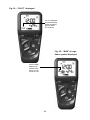
3.3 Fitting the batteries (remote control models) 25
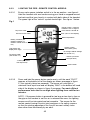
3.4 Lighting the fire manually via the control valve (remote control models) 26
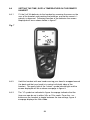
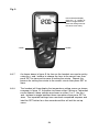
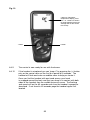
3.5 Setting the time, temperature and day on the remote handset (remote models) 27-30
3.6 Lighting the fire via the remote handset (remote control models) 31-33
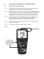
3.7 Advanced settings of remote control models 34-38
3.9 Fitting the Decadence fascia 39
3.10 Checking for clearance of combustion products 40
Section 4 & 5 Maintenance
4.1 Removal of the burner assembly (manual control models) 41
4.2 Removal of the piezo igniter (manual control models) 42
4.3 Removal of the control tap (manual control models) 42
4.4 Removal of the pilot assembly (manual control models) 42
5.1 Removal of the burner assembly (remote control models) 43
5.2 Removing the remote gas valve 43
5.3 Removing the oxy-pilot assembly (remote control models) 44
5.4 Replacing the batteries (remote control models) 44
5.5 Parts shortlist 45
Section 6 User Instruction Section
6.1 Conditions of Installation & about your new fire 46-47
6.2 Operating the fire - manual & remote control variants 48-52
6.3 Manual operation of remote control models 53-54
6.4 Replacing the batteries on remote control models 54
6.5 Spillage monitoring system 55
6.6 Setting the time, day & temperature on the remote handset 56-59
6.7 Advanced settings menu of the remote control 60-63
6.8 Re-assembling the ceramics & fuel-bed - coal models 64-68
6.9/10 Cleaning the fire & fuel-bed / glass panel 69-70
6.11 Removal & re-fitting of the glass panel 71-72
6.12 Removal & re-fitting the Decadence fascia 73
6.13 User replaceable parts 73
2

SECTION 1
INFORMATION AND REQUIREMENTS
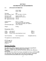
1.0 APPLIANCE INFORMATION
Model FHKC**MN2
FHKC**RN3
Gas type G20
Main injectors (2 off) Size 130 (MC) 170 (RC)
Pilot type (MC) Copreci 21100 / 141
Pilot type (RC) ERTA OXYP PG-83-10
Max. gross heat input : 4.5 kW
Min. gross heat input : 3.5 kW
Cold pressure : 20.0 +/- 1.0 mbar
Ignition : Push button piezo (MC models)
4.5V battery generator (RC models)
Electrode spark gap 4.5mm nominal
Weight 25.5kg
Dimensions of Fire
Width : (with fascia) 529mm
Height : (with fascia) 631mm
Depth : Flush-fit (from mounting face to rear) 180mm
Gas Connection 8mm Compression (Supplied with fire)
This appliance is manufactured by :-
BFM Europe Ltd,
Trentham Lakes,
Stoke-on-Trent,
ST4 4TJ.
Efficiency Declaration
The efficiency of this appliance has been measured as specified in
BS 7977-1 : 2009 + A1 : 2013 and the result is 76.6%.
The gross calorific value of the fuel has been used for this efficiency
calculation.
The test data from which it has been calculated has been certified by BSI.
The efficiency value may be used in the UK Government’s Standard
Assessment Procedure (SAP) for energy rating of dwellings.
3

INSTALLATION REQUIREMENTS
1.1 CONDITIONS OF INSTALLATION
It is the law that all gas appliances are installed only by a Registered Installer, in
accordance with these installation instructions and the Gas Safety (Installation and
Use) Regulations 1998 as amended. Failure to install appliances correctly could
lead to prosecution. It is in your own interest and that of safety to comply with the
law.
The installation must also be in accordance with all relevant parts of the Local and
National Building Regulations where appropriate, the Building Regulations
(Scotland Consolidation) issued by the Scottish Development Department, and all
applicable requirements of the following British Standard Code of Practice.
1. BS 5871 Part 2 Installation of Inset Fuel Effect Gas Fires
2. BS 6891 Installation of Gas Pipework
3. BS 5440 Parts 1 & 2 Installation of Flues and Ventilation
4. BS 1251 Open fire place components
5. BS 715 / BS EN 1856-2 Metal flue pipes for gas appliances
6. BS 6461 Part 1 Installation of masonary chimneys and flues
7. IS 813 : 1996 Domestic Gas Installation (Republic of Ireland)
No purpose made additional ventilation is normally required for this
appliance, when installed in G.B. When Installing in I.E. please consult
document I.S. 813 : 1996 Domestic Gas Installation, which is issued by the
National Standards Authority of Ireland. If installing in Northern Ireland,
please consult local building regulations. In Scotland, please consult the
current edition of the Building standards regulations, issued by the Scottish
Executive. Any purpose made ventilation must be checked periodically to
ensure that it is free from obstruction.
1.2 FLUE AND CHIMNEY SUITABILITY
This appliance is designed for use with conventional brick built or lined chimneys
and fabricated flues and metal flue boxes conforming to BS 715 / BS EN 1856-2.
All flues must conform to the following minimum dimensions.
Minimum diameter of circular flues 125 mm (Without flue
restrictor fitted)
Minimum effective height of all flue types 4 metres
When fitting to conventional chimneys or 175mm flues it may be desirable to
fit the flue restrictor baffle (supplied) to reduce the flue flow and increase the
efficiency of the fire. Safe clearance of products must always be checked by
carrying out a smoke match test as described.
4

1.3 FIREPLACE / SURROUND SUITABILITY
The fire must only be installed on a hearth it must not be installed directly onto
carpet or other combustible floor materials. The fire is suitable for fitting to
non-combustible fire place surrounds and proprietary fire place surrounds with a
temperature rating of at least 150
o
c. (Class “O”)
If a heating appliance is fitted directly against a wall without the use of a fire
surround or fire place all combustible material must be removed from behind
the trim. Soft wall coverings such as blown vinyl, wall paper etc. could be
affected by the rising hot air and scorching and / or discoloration may result.
Due consideration should be made to this when installing or decorating.
1.4 SHELF POSITION
The fire may be fitted below a combustible shelf providing there is a minimum
distance of 200mm above the top of the fire and the shelf does not project more
than 150mm. If the shelf overhangs more than 150mm the distance between the
fire and the shelf must be increased by 15mm for every 25mm of additional
overhang over 150mm.
1.5 FLUE / CHIMNEY INSPECTION
Before commencing installation, a flue or chimney should be inspected to ensure
that all the following conditions are satisfied.
1. Check that the chimney / flue only serves one fire place and is clear of any
obstruction. Any dampers or register plates must be removed or securely
locked in the open position.
2. Brick / stone built chimneys or any chimney or flue which has been used
for an appliance burning fuel other than gas must be thoroughly swept.
The base of the chimney / flue must also be thoroughly cleared of debris
etc.
3. Any under-floor air supply to the fire place must be completely sealed off.
4. Ensure that the inside of the chimney / flue is in good condition along it’s
length and check that there is no leakage of smoke through the structure
of the chimney during and after the smoke pellet test.
5. Using a smoke pellet, check that there is an up-draught in the
chimney / flue and that the smoke can be seen issuing from the
terminal / chimney pot outside.
There must be no leakage of smoke through the structure of
the chimney during or after the smoke pellet test and it is
important to check inside upstairs rooms adjacent to the chimney /
flue.
5

Check the chimney pot / terminal and general condition of the
brickwork or masonry. If the chimney or flue is in poor condition or if
there is no up-draught do not proceed with the installation. If there is a
history of down-draught conditions with the chimney / flue, a tested and
certificated flue terminal or cowl suitable for the relevant flue type should
be considered.
6. A spillage test must always be carried out during commissioning of
the appliance.
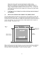
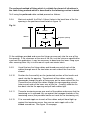
1.6 FIRE PLACE OPENING AND CHIMNEY CATCHMENT SPACE
The front opening of the fire place must be between 370 and 450 mm wide, and
between 550 and 570mm high. If the opening exceeds these dimensions then a
surround must be constructed from suitable non-combustible material to produce a
correct size opening. Any surround must be suitably sealed to the fire place to
prevent leakage. See below in fig.1
When installing into a brick built chimney, you must ensure that there is sufficient
depth to accomodate any debris which may fall from the chimney. This depth
must be sufficient to accomodate 12 litres of volumetric space.
Fire Opening
370mm Minimum
450mm Maximum
580mm
Minimum
470mm Minimum
Fig. 1
550mm Minimum
570mm Maximum
Minimum Flat
Sealing Area
6

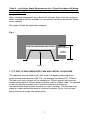
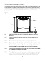
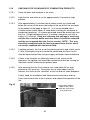
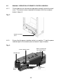
Table A - Installation Depth Requirements for a Flavel Decadence HE being
installed into a brick built chimney, requiring 12.0 litres of debris collection
volume (figure 2).
When installing this product into a brick built chimney, there must be a minimum
depth available of 200mm available for the collection of debris behind the firebox
when installed.
See figure 2 below for explanatory diagram.
Fig. 2
1.7 FITTING TO PRE-FABRICATED TWIN WALL METAL FLUE BOXES
The appliance may be fitted to twin wall metal flue boxes conforming to the
constructional requirements of BS 715, (for example the Selkirk LFE 175 box).
The box must have a minimum flue diameter of 125mm internal and minimum
internal dimensions of 275mm deep by 580mm high by 400mm wide. The top face
of the box must be insulated with a minimum thickness of 50mm of
non-combustible mineral wool insulation or similar material. The flue box must
stand on a non-combustible base of minimum thickness 12mm if the flue box
being utilised is of single skin construction.
7
Firebox
Depth Required
200mm
Minimum
VOID FOR FLUE DEBRIS COLLECTION

1.8 FITTING TO PRE-CAST FLUES
When installing this appliance into pre-cast flues, always ensure that the
spigot restrictor baffle has been removed.
To install the fire box in to pre-cast flue starter blocks, there must be at least
180mm from the mounting face of the fire to the rear of the pre-cast flue
starter block to allow sufficient space for debris collection. It is important to
consider this depth when choosing a fire surround as the thickness of the fire
surround must be sufficient to give a total depth of at least 180 mm to the rear of
the starter block, otherwise there will be insufficient depth. This fire has been
designed to fit standard 100mm pre-cast starter blocks with 3 inch rebated
surrounds and a 10mm plaster wall covering. It is important to ensure that the
pre-cast flue is in good condition and is free from extruded mortar or sealant from
between the flue blocks.
This appliance has been tested for use in a pre-cast flue block complying
with BS EN 1858. In accordance with BS EN 1858, pre-cast flues built with
directly plastered faces (front or rear) are not correctly installed as to ensure
proper operation with any type of gas fire. In some instances of this flue
construction, temperature cracking of surface plaster may occur through no
fault of the appliance. An air gap or some form of insulation material should
be installed to prevent normal flue temperatures from damaging wall
surfaces.
1.9 SPILLAGE MONITORING SYSTEM
This appliance is fitted with an atmosphere sensing spillage monitoring system in
the form of an oxygen sensing pilot. This is designed to shut the fire off in the
event of a partial or complete blockage of the flue causing a build up of
combustion products in the room in which the fire is operated. The following are
important warnings relating to this spillage monitoring system :-
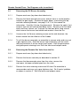
1.9.1 The spillage monitoring system must not be adjusted by the installer.
1.9.2 The spillage monitoring system must not be put out of operation.
1.9.3 When the spillage monitoring system is exchanged only a complete
original manufacturers part may be fitted. It is not possible to replace
individual parts on the pilot system on this appliance, only a complete
pilot assembly (including the thermocouple) may be fitted.
8

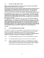
SECTION 2
INSTALLATION OF FIRE
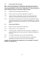
2.1 UNPACKING THE FIRE
Carefully lift the fire out of the carton. Remove the loose item packaging carefully
from the front of the appliance. Check the contents as listed :-
Packing Check List
1 off Fire box / burner assembly
1 off Boxed ceramic base, front ceramic rail and 7 coals
1 off Loose items bag including remote handset and 5 off AA batteries on RC
models.
1 off Flue restrictor baffle
1 off Installation & maintenance / user instruction book (combined)
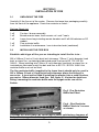
2.2 INSTALLING THE FIRE BOX
Establish which type of flue you are intending to install the fire in to :-
225 x 225mm (9 inch x 9 inch) brick built chimneys 175mm (7 inch) diameter lined
brick or stone flue, insulated pre-fabricated metal flue box to BS 715 / BS EN
1856-2. When installing into 125mm (5 inch) diameter lined brick or stone flue, or
insulated pre-fabricated metal flue box and liner to BS 715 / BS EN 1856-2 the
restrictor baffle must not be fitted.
The flue restrictor baffle (supplied in the loose items) should only be used in
225 x 225mm (9 inch x 9 inch) brick built chimneys where the flue pull is
excessive. It must not be fitted if installing the product into a metal flue box,
pre-cast or 125mm diameter lined flue. See figure 3 / 4 below for details on
fitting / removing the restrictor baffle onto the spigot on the rear of the
firebox.
A spillage test must always be carried out to check satisfactory clearance of
flue products, regardless of the type of flue the appliance is being fitted to.
9
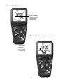
Fig 3 - Flue Restrictor
Baffle Not Fitted
Fig 4 - Flue Restrictor
Baffle Fitted via 3 screws
as shown
3 screws

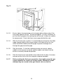
For all models proceed as follows :-
2.2.1 Remove the top glass retaining cover from the product. It is secured via
the two screws as indicated. See figure 5 below.
Fig. 5
2.2.2 Remove the left and right hand side glass securing brackets from the
product. They are secured via 3 off screws each side. See figure 6
below.
Fig. 6
10
2 off securing
screws
3 off securing
screws L/H/S
3 off securing
screw R/H/S

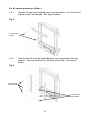
2.2.3 Lift the glass panel forwards and clear from the firebox, taking care not
to damage the glass panel. See figure 7 below.
Fig. 7
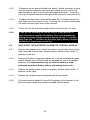
2.2.4 Remove the burner heat shield, which is retained by 2 off screws as
shown below in figure 8.
Fig. 8
11
Burner heat
shield retaining
screws

For all manual control models proceed as follows :-
2.2.5 Remove the two off screws from the left and right hand burner
mounting brackets, plus the two screws from the base of the control
panel as shown below in figure 9, this will allow removal of the
complete burner unit from the firebox.
Fig. 9
For all remote control models proceed as follows :-
2.2.6 Remove the two off screws from the left and right hand burner
mounting brackets, plus the two screws from the base of the control
panel as shown below in figure 10, this will allow removal of the
complete burner unit from the firebox.
Fig. 10
12
4 off burner
retaining screws
4 off burner
retaining screws

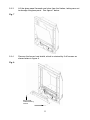
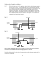
Continue for all models as follows :-
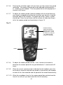
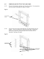
2.2.7 Whilst the fire box is still in position, decide which side the gas supply is
to enter the fire from. If concealed pipe work is required plan the pipe
run to enter the fire box through one of the openings in the sides or rear
of the fire box below the fuelbed support panel and connect to the
isolating / inlet elbow. The gas connection to the appliance should be
made to the isolating / inlet elbow using 8mm rigid tubing. There must
be no soldered joints within the firebox. See figure 11 & 12 below for
suggested concealed pipe layouts.
Fig. 11
Fig. 12
Note : Before breaking into the gas supply a pressure drop test should be
carried out to establish that the existing pipework is sound.
Carefully withdraw the fire box from the opening to enable the gas supply and fire
fixing to be completed.
13
Firebox
Fireplace
Builders
Opening
Gas Supply
Firebox
Approx.
40mm
Fireplace
Gas Supply
Approx.
40mm
Builders
Opening

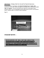
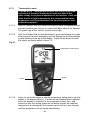
IMPORTANT : Sealing of the Gas Unused Gas Pipe Inlet Apertures
In line with current regulations, it is imperative that the gas supply inlet
apertures that are not utilised during the installation are sealed with the foil
tape as supplied. Failure to seal these inlet apertures could lead to flame
reversal, which in turn will damage the burner and control systems of the product.
figure 13 below shows a correctly sealed installation.
Fig. 13
PLEASE NOTE :-
BFM EUROPE LTD. WILL NOT BE LIABLE FOR
GUARANTEE CLAIMS THAT ARE AS A DIRECT
RESULT OF THE UNUSED GAS INLET APERTURES
NOT BEING CORRECTLY SEALED.
Seal off unused gas inlet
apertures as shown
14

The preferred method of fixing which is suitable for almost all situations is
the cable fixing method which is described in the following section in detail.
To fit using the preferred cable method proceed as follows-
2.2.8 Mark out and drill 4 off No 14 (6mm) holes in the back face of the fire
opening in the positions shown below in figure 14.
Fig. 14
Fit the wallplugs provided and screw the fixing eyes securely into the rear of the
fire opening. If the clearance at the rear of the fire is at the minimum specified for
a precast flue application, it may be necessary to bend over the lower fixing eyes
after screwing them fully in to the rear of a pre-cast starter block.
2.2.9 Uncoil the two fire fixing cables and thread one end of each of the
cables through one of the two holes on each side of the flue outlet
shroud.
2.2.10 Position the fire carefully on the (protected) surface of the hearth and
reach into the fire opening. Thread each of the cables vertically
downwards through the pair of fixing eyes on the same side of the fire.
Thread the free end of the cables through the corresponding circular
hole on each side of the lower rear of the fire. Carefully slide the fire
box back into the fire opening and pull both cables tight.
2.2.11 Thread a tensioning screw over each of the cables and ensure that the
tensioning nut is screwed fully up against the hexagon shoulder of the
tensioning screw (this provides maximum travel for the tensioning nut).
2.2.12 Fit a screwed nipple on to each of the cables and pull hand tight up
against the tensioning screw, then secure each nipple with a flat
bladed screwdriver. See figure 15 overpage.
15
20mm
500mm
Fireplace Opening
100mm
250mm

Fig. 15
2.2.13 Evenly tighten the tensioning nuts to tension both cables and pull the
fire snugly against the wall. Do not overtighten, it is only necessary to
pull the seal up against the sealing face of the wall, it does not need to
be compressed. Check that there are no gaps behind the seal.
2.2.14 With the fire securely in place, if a concealed gas connection has been
made through either of the access holes in the sides of the fire, the
holes should be closed around the pipe to prevent leakage of air
through the gap around the pipe.
2.2.15 Refit the burner. Fit the four retaining screws on manual control
models or two screws on remote control models and check that the
burner is correctly locked into position.
2.2.16 Refit the front burner heat shield to the sides of the fire box (2 screws)
and secure the trim to the fire using the magnets provided.
2.2.17 Before making the final gas connection, thoroughly purge the gas
supply pipework to remove all foreign matter, otherwise serious
damage may be caused to the gas control valve on the fire.
16

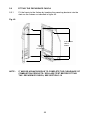
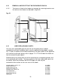
The other firebox fixing method is as follows :-
In installations where the cable method is not suitable (e.g. loose masonary in rear
of fire opening) the firebox can be secured to the fire surround using four screws
and wall plugs provided. Below (figure 16) is a diagram to indicate the hole centre
positions available on the firebox to facilitate the screw fixing to the fireplace /
surround.
Fig. 16
2.3 GAS TIGHTNESS AND INLET PRESSURE (MANUAL CONTROL
MODELS)
2.3.1 Remove the pressure test point screw from the inlet elbow and fit a
manometer.
2.3.2 Turn on the main gas supply and carry out a gas tightness test.
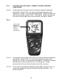
2.3.3 Depress the control knob and turn anti-clockwise to the position marked
pilot. Hold in the control knob for a few seconds to purge the pipe work
then press the igniter button. The burner should light, continue to hold
the control knob for a few seconds then turn to the full-on position.
2.3.4 Check that the gas pressure for Natural Gas (G20) models is 20.0 mbar
(+/- 1.0mbar) 8.0 in w.g.(+/- 0.4 in w.g.)
2.3.5 Turn off the fire, remove the manometer and refit the pressure test point
screw. Check the pressure test point screw for gas tightness with the
appliance turned on using a suitable leak detection fluid or detector.
17
512mm
260mm
50mm
Firebox
Mounting
Flange
426mm

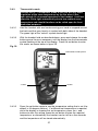
2.4 GAS TIGHTNESS AND INLET PRESSURE (REMOTE CONTROL
MODELS).
2.4.1 Remove the pressure test point screw from the inlet elbow and fit a
manometer.
2.4.2 Turn on the main gas supply and carry out a gas tightness test.
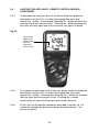
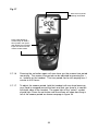
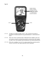
2.4.3 Depress both the round buttons on the handset. The fire will then
commence its ignition sequence and will light to high. See page 25-38
for full details of the operating method for the fire.
2.4.4 Check that the gas pressure is 20.0 mbar (+/- 1.0mbar) 8.0 in w.g.(+/-
0.4 in w.g.)
2.4.5 Turn off the fire, remove the manometer and refit the pressure test point
screw. Check the pressure test point screw for gas tightness with the
appliance turned on using a suitable leak detection fluid or detector.
18

SECTION 3
ASSEMBLING FUEL BED AND COMMISSIONING
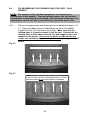
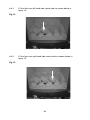
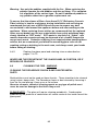
3.1 ASSEMBLING THE CERAMICS AND FUEL BED - COAL MODELS
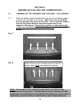
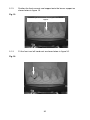
3.1.1 Place the ribbed ceramic fuelbed base on top of the fuelbed support
and pull fully forwards to the burner. Make sure that the fuelbed
base is located centrally in the fire box. Ensure that the fuelbed
base fit fully down onto the fuel bed support and is not
lodged on the burner. Ensure the air ports as indicated by the
arrows are not blocked by the fuel-bed matrix. See figure 17 & 18
below.
Fig. 17
Fig. 18
19
Check air ports in fuel-bed base panel are not obstructed.
If these air ports are not in line with the holes in the fuel-
bed base matrix do not
proceed with the installation
Air ports in Fuelbed base mounting panel
NOTE : The position of the fuel-bed components are critical to the
performance of the product. Therefore please ensure that the fuel-bed
components are positioned as described in the following section prior to
requesting a service call due to soot build up, poor flame pattern etc.
Page is loading ...
Page is loading ...
Page is loading ...
Page is loading ...
Page is loading ...
Page is loading ...
Page is loading ...
Page is loading ...
Page is loading ...
Page is loading ...
Page is loading ...
Page is loading ...
Page is loading ...
Page is loading ...
Page is loading ...
Page is loading ...
Page is loading ...
Page is loading ...
Page is loading ...
Page is loading ...
Page is loading ...
Page is loading ...
Page is loading ...
Page is loading ...
Page is loading ...
Page is loading ...
Page is loading ...
Page is loading ...
Page is loading ...
Page is loading ...
Page is loading ...
Page is loading ...
Page is loading ...
Page is loading ...
Page is loading ...
Page is loading ...
Page is loading ...
Page is loading ...
Page is loading ...
Page is loading ...
Page is loading ...
Page is loading ...
Page is loading ...
Page is loading ...
Page is loading ...
Page is loading ...
Page is loading ...
Page is loading ...
Page is loading ...
Page is loading ...
Page is loading ...
Page is loading ...
Page is loading ...
Page is loading ...
Page is loading ...
-
 1
1
-
 2
2
-
 3
3
-
 4
4
-
 5
5
-
 6
6
-
 7
7
-
 8
8
-
 9
9
-
 10
10
-
 11
11
-
 12
12
-
 13
13
-
 14
14
-
 15
15
-
 16
16
-
 17
17
-
 18
18
-
 19
19
-
 20
20
-
 21
21
-
 22
22
-
 23
23
-
 24
24
-
 25
25
-
 26
26
-
 27
27
-
 28
28
-
 29
29
-
 30
30
-
 31
31
-
 32
32
-
 33
33
-
 34
34
-
 35
35
-
 36
36
-
 37
37
-
 38
38
-
 39
39
-
 40
40
-
 41
41
-
 42
42
-
 43
43
-
 44
44
-
 45
45
-
 46
46
-
 47
47
-
 48
48
-
 49
49
-
 50
50
-
 51
51
-
 52
52
-
 53
53
-
 54
54
-
 55
55
-
 56
56
-
 57
57
-
 58
58
-
 59
59
-
 60
60
-
 61
61
-
 62
62
-
 63
63
-
 64
64
-
 65
65
-
 66
66
-
 67
67
-
 68
68
-
 69
69
-
 70
70
-
 71
71
-
 72
72
-
 73
73
-
 74
74
-
 75
75


Flavelfires Decadence HE Gas Fire User manual
- Type
- User manual
- This manual is also suitable for
Ask a question and I''ll find the answer in the document
Finding information in a document is now easier with AI
Related papers
-
Flavel Linear HE Gas Fire User manual
-
-
-
-
-
-
-
-
-
Other documents
-
-
-
-
-
-
-
-
 PUREGLOW EAR16NG Installation & User Manual
-
Vision V1/400/A Installation & User's Instructions
-
