
Serial Number
Decal
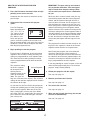
USERʼS MANUAL
CAUTION
Read all precautions and instruc-
tions in this manual before using
this equipment. Keep this manual
for future reference.
Model No. WLEL93908.0
Serial No.
Write the serial number in the
space above for future reference.
QUESTIONS?
As a manufacturer, we are commit-
ted to providing complete customer
satisfaction. If you have questions,
or if parts are damaged or missing,
DO NOT CONTACT THE STORE;
please contact Customer Care.
IMPORTANT: You must note the
product model number and serial
number (see the drawing above)
before contacting us:
CALL TOLL-FREE:
1-866-699-3756
Mon.–Fri. 6 a.m.–6 p.m. MT
Sat. 8 a.m.–4 p.m. MT
ON THE WEB:
www.wesloservice.com
www.weslo.com

TABLE OF CONTENTS
W
ARNING DECAL PLACEMENT . . . . . . . . . . . . . . . . . . . . . . . . . . . . . . . . . . . . . . . . . . . . . . . . . . . . . . . . . . . . . .2
IMPORTANT PRECAUTIONS . . . . . . . . . . . . . . . . . . . . . . . . . . . . . . . . . . . . . . . . . . . . . . . . . . . . . . . . . . . . . . . .3
BEFORE YOU BEGIN . . . . . . . . . . . . . . . . . . . . . . . . . . . . . . . . . . . . . . . . . . . . . . . . . . . . . . . . . . . . . . . . . . . . . .4
ASSEMBLY . . . . . . . . . . . . . . . . . . . . . . . . . . . . . . . . . . . . . . . . . . . . . . . . . . . . . . . . . . . . . . . . . . . . . . . . . . . . . . .5
HOW TO USE THE ELLIPTICAL EXERCISER . . . . . . . . . . . . . . . . . . . . . . . . . . . . . . . . . . . . . . . . . . . . . . . . . .10
M
AINTENANCE AND TROUBLESHOOTING . . . . . . . . . . . . . . . . . . . . . . . . . . . . . . . . . . . . . . . . . . . . . . . . . . .18
EXERCISE GUIDELINES . . . . . . . . . . . . . . . . . . . . . . . . . . . . . . . . . . . . . . . . . . . . . . . . . . . . . . . . . . . . . . . . . . .19
PART LIST . . . . . . . . . . . . . . . . . . . . . . . . . . . . . . . . . . . . . . . . . . . . . . . . . . . . . . . . . . . . . . . . . . . . . . . . . . . . . .20
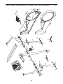
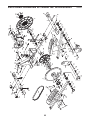
EXPLODED DRAWING . . . . . . . . . . . . . . . . . . . . . . . . . . . . . . . . . . . . . . . . . . . . . . . . . . . . . . . . . . . . . . . . . . . .22
ORDERING REPLACEMENT PARTS . . . . . . . . . . . . . . . . . . . . . . . . . . . . . . . . . . . . . . . . . . . . . . . . . .Back Cover
LIMITED WARRANTY . . . . . . . . . . . . . . . . . . . . . . . . . . . . . . . . . . . . . . . . . . . . . . . . . . . . . . . . . . . . . .Back Cover
2
WESLO is a registered trademark of ICON IP, Inc.
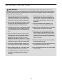
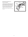
WARNING DECAL PLACEMENT
This drawing shows the location(s) of the
warning decal(s). If a decal is missing or
illegible, see the front cover of this
manual and request a free replacement
decal. Apply the decal in the location
shown. Note: The decal(s) may not be
shown at actual size.

3
WARNING: To reduce the risk of serious injury, read all important precautions and
instructions in this manual and all warnings on your elliptical exerciser before using your elliptical
exerciser. ICON assumes no responsibility for personal injury or property damage sustained by or
t
hrough the use of this product.
IMPORTANT PRECAUTIONS
1. Before beginning any exercise program,
consult your physician. This is especially
important for persons over the age of 35 or
persons with pre-existing health problems.
2. It is the responsibility of the owner to ensure
that all users of the elliptical exerciser are
adequately informed of all precautions.
3. The elliptical exerciser is intended for home
use only. Do not use the elliptical exerciser
in a commercial, rental, or institutional set-
ting.
4. Keep the elliptical exerciser indoors, away
from moisture and dust. Place the elliptical
exerciser on a level surface, with a mat
beneath it to protect the floor or carpet.
Make sure that there is at least 3 ft. (1 m) of
clearance in the front and rear of your ellipti-
cal exerciser and 2 ft. (0.6 m) on each side.
5. Inspect and properly tighten all parts regu-
larly. Replace any worn parts immediately.
6. Keep children under age 12 and pets away
from the elliptical exerciser at all times.
7. The elliptical exerciser should not be used
by persons weighing more than 250 lbs.
(113 kg).
8. Wear appropriate exercise clothes while
exercising; do not wear loose clothes that
could become caught on the elliptical exer-
ciser. Always wear athletic shoes for foot
protection.
9. Hold the handlebars while mounting, dis-
mounting, or using the elliptical exerciser.
10. Keep your back straight while using the ellip-
tical exerciser; do not arch your back.
11. The pulse sensor is not a medical device.
Various factors, including the userʼs move-
ment, may affect the accuracy of heart rate
readings. The pulse sensor is intended only
as an exercise aid in determining heart rate
trends in general.
12. When you stop exercising, allow the pedals
to slowly come to a stop.
13. If you feel pain or dizziness while exercising,
stop immediately and cool down.
14. Use the elliptical exerciser only as described
in this manual.

4
BEFORE YOU BEGIN
Congratulations for selecting the new WESLO
®
MOMENTUM R 7.8 elliptical exerciser. The MOMEN-
T
UM R 7.8 is a smooth exerciser that moves your feet
in a natural elliptical path, minimizing the impact on
your knees and ankles.
For your benefit, read this manual carefully before
you use the elliptical exerciser. If you have ques-
tions after reading this manual, please see the front
cover of this manual. To help us assist you, note the
product model number and serial number before con-
tacting us. The model number and the location of the
serial number decal are shown on the front cover of
t
his manual.
To avoid a registration fee for any service needed
under warranty, you must register the elliptical
exerciser at www.wesloservice.com/registration.
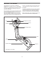
Before reading further, please familiarize yourself with
the parts that are labeled in the drawing below.
Handgrip Pulse Sensor
Handlebar
Pedal Disc
Wheel
Adjustment Knob
Pedal
Console
Water Bottle Holder*
Fan
*Water bottle is not included

5
M10 x 112mm Carriage Bolt (34)–4
M10 x 88mm Button Screw (63)–2
M10 x 52mm Bolt Set (27)–2
M8 x 65mm Button Screw (99)–4
M10 Split
Washer (70)–2
M8 Large
Washer (53)–10
Wave Washer
(95)–2
M8 Split
Washer (100)–4
M8 x 25mm Patch
Screw (22)–2
M8 x 50mm Button
Screw (89)–4
M8 x 45mm Button
Bolt (50)–4
M10 Locknut
(29)–4
M8 Locknut
(46)–8
M4 x 16mm
Screw (66)–4
M4 x 22mm
Screw (91)–2
ASSEMBLY
To hire an authorized service technician to assemble the elliptical exerciser, call 1-800-445-2480.
Assembly requires two persons. Place all parts of the elliptical exerciser in a cleared area and remove the
packing materials. Do not dispose of the packing materials until assembly is completed.
I
n addition to the included tool(s), assembly requires a Phillips screwdriver , an adjustable
wrench , and a rubber mallet .
As you assemble the elliptical exerciser, use the drawings below to identify small parts. The number in parenthe-
ses below each drawing is the key number of the part, from the PART LIST near the end of this manual. The
number following the parentheses is the quantity needed for assembly. Note: Some small parts may have
been preassembled. If a part is not in the hardware kit, check to see if it has been preassembled.

6
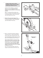
1.
Identify the Front Stabilizer (3), which has
Wheels (32) attached. Orient the Front
Stabilizer so that the Wheels are not touching
the floor.
While a second person lifts the front of the
Frame (1), attach the Front Stabilizer (3) to the
Frame with two M10 x 112mm Carriage Bolts
(34) and two M10 Locknuts (29).
3
29
32
32
34
1
1
2. While another person lifts the back of the
Frame (1), attach the Rear Stabilizer (4) to the
Frame with two M10 x 112mm Carriage Bolts
(34) and two M10 Locknuts (29).
34
4
1
3
2
86
87
1
63
83
70
70
91
105
83
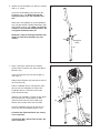
3. While a second person holds the Upright (2)
near the Frame (1), connect the Upper Wire
Harness (86) to the Lower Wire Harness (87).
Tip: Avoid pinching the Wire Harnesses (86,
87). Insert the Upright (2) into the Frame (1).
Slide an M10 Split Washer (70) and a Frame
Spacer (83) onto each of the two M10 x 88mm
Button Screws (63). Insert the Button Screws
into the Frame (1) and the Upright (2). Make
sure that the concave ends of the Frame
Spacers are facing the Frame. Do not tighten
the Button Screws yet.
Attach the Water Bottle Holder (105) to the
Upright (2) with two M4 x 22mm Screws (91).
2
29
29
Avoid pinching
the wires
To make assembly easier, read the
information on page 5 before you begin
assembling the elliptical exerciser.

7
5. While a second person holds the Console (5)
near the Upright (2), connect the console wire
harness to the Upper Wire Harness (86).
Insert the excess wire harness into the Upright
(2).
Tip: Avoid pinching the wires. Attach the
Console (5) to the Upright (2) with four M4 x
16mm Screws (66).
5
86
66
2
Wire
Harness
5
4. The Console (5) can use four 1.5V D batteries
(
not included); alkaline batteries are recom-
mended. IMPORTANT: If the Console has
been exposed to cold temperatures, allow it
to warm to room temperature before insert-
i
ng batteries. Otherwise, you may damage
the console displays or other electronic
components. Remove the battery cover, insert
the batteries into the battery compartment, and
reattach the battery cover. Make sure to orient
the batteries as shown by the diagram
inside the battery compartment.
To purchase an optional AC adapter, contact
the store where you purchased this product
or call the telephone number on the cover of
this manual. To avoid damaging the console,
use only a manufacturer-supplied AC
adapter. Plug one end of the AC adapter into
the jack on the console; plug the other end into
an outlet installed in accordance with all local
codes and ordinances.
4
5
Batteries
Battery
Cover
Avoid pinching
the wires

8
Grease
Tube
Arrow
7
97
25
9
2
23
22
53
79
95
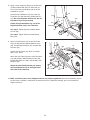
7. Apply a generous amount of the included
grease to the Pivot Axle (97) and to two Wave
Washers (95).
Insert the Pivot Axle (97) into the Upright (2)
and center it.
Slide a Waver Washer (95) onto the left side of
the Pivot Axle (97).
Slide a Handlebar Spacer (25) onto the short
tube on the Left Handlebar (9). Rotate the
Handlebar Spacer so that the small arrow
points toward the floor.
Slide the Left Handlebar (9) onto the left end of
the Pivot Axle (97). Finger tighten an M8 x
25mm Patch Screw (22) and an M8 Large
Washer (53) into the end of the Pivot Axle.
Attach a Handlebar Cap (23) by pressing its
small tabs into the Handlebar Spacer (25).
Assemble the Right Handlebar (not shown)
in the same way.
Tighten both M8 x 25mm Patch Screws (22)
at the same time.
6
6. Identify the Left Handlebar (9), which is marked
with an “L” sticker.
I
nsert the Left Handlebar (9) into one of the
Handlebar Legs (79). Make sure that the
h
exagonal holes are in the indicated loca-
tion.
Attach the Left Handlebar (9) to the Handlebar
Leg (79) with two M8 x 45mm Button Bolts (50)
and two M8 Locknuts (46). Make sure that the
Locknuts are inside the hexagonal holes. Do
not tighten the Button Bolts yet.
Repeat this step for the Right Handlebar (not
shown) and the other Handlebar Leg (not
shown).
50
46
Hexagonal
Holes
9
79

9
10. Make sure that all parts of the elliptical exerciser are properly tightened. Note: Some hardware may be
left over after assembly is completed. To protect the floor or carpet from damage, place a mat under the
elliptical exerciser.
9
12
16
99
14
9. Attach a Pedal Bracket (16) to the Left Pedal
Arm (14) with two M8 x 65mm Button Screws
(99), two M8 Large Washers (53), and two M8
Locknuts (46).
Identify the Left Pedal (13), which is marked
with a “Left” sticker.
Attach the Left Pedal (13) to the Left Pedal Arm
(14) with two M8 x 50mm Button Screws (89),
two M8 Split Washers (100), and two M8 Large
Washers (53).
Attach the other Pedal Bracket (not shown)
and the Right Pedal (12) to the Right Pedal
Arm (103) in the same way.
103
53
53
53
89
100
13
46
8. Apply a small amount of grease to the barrel of
a
n M10 x 52mm Bolt Set (27) and to the sur-
faces of the two Leg Bushings (28) in the left
H
andlebar Leg (79).
Attach the left Handlebar Leg (79) to the Left
Pedal Arm (14) with the M10 x 52mm Bolt Set
(
27). Do not overtighten the Bolt Set; the left
Handlebar Leg must pivot freely.
Attach the right Handlebar Leg (79) to the
Right Pedal Arm (103) in the same way.
See step 3. Tighten the M10 x 88mm Button
Screws (63).
See step 6. Tighten the M8 x 45mm Button
Bolts (50).
14
103
27
27
28
2
8
Grease
Grease
8
79
79

10
HOW TO USE THE ELLIPTICAL EXERCISER
HOW TO MOVE AND LEVEL THE ELLIPTICAL
E
XERCISER
To move the elliptical exerciser, stand in front of it,
place one foot against one of the wheels, and firmly
h
old the upper end of the upright. Pull the upright for-
ward until you can move the elliptical exerciser on the
wheels. Carefully move the elliptical exerciser to the
desired location and then lower it. To decrease the
risk of injury, do not attempt to move the elliptical
exerciser over an uneven surface.
If the elliptical exerciser rocks slightly on your floor,
turn one or both of the leveling feet under the front
stabilizer until the rocking motion is eliminated.
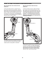
HOW TO EXERCISE ON THE ELLIPTICAL
E
XERCISER
To mount the elliptical exerciser, hold the handgrip
pulse sensor and step onto the pedal that is in the
l
ower position. Next, step onto the other pedal. Push
the pedals until they begin to move with a continuous
motion. Note: The pedal discs can turn in either
direction. It is recommended that you move the
pedal discs in the direction shown by the arrow;
however, for variety, you can turn the pedal discs
in the opposite direction.
To dismount the elliptical exerciser, wait until the ped-
als come to a complete stop. Note: The elliptical
exerciser does not have a free wheel; the pedals
will continue to move until the flywheel stops.
When the pedals are stationary, step off the higher
pedal first. Then, step off the lower pedal.
Pedals
Pedal Disc
Handlebars
Upright
Wheel
Leveling
Foot

11
HOW TO ADJUST THE STRIDE OF THE
E
LLIPTICAL EXERCISER
T
o adjust the stride of the elliptical exerciser, first pull
one of the adjustment knobs until the adjustment
bracket will pivot freely. Pivot the adjustment bracket
to align the adjustment knob with one of the three
h
oles in the crank arm, and gently release the knob.
Then, pivot the adjustment bracket back and forth
slightly to make sure that the adjustment pin is
engaged in one of the holes in the crank arm.
Adjust the other side of the elliptical exerciser in the
same way.
A
djustment
Bracket
Adjustment
Knob
Adjustment
Pin
Crank
Arm
Holes

12
FEATURES OF THE CONSOLE
The advanced console offers an array of features
designed to make your workouts more effective and
enjoyable.
When you use the manual mode of the console, you
can change the resistance of the pedals with the touch
of a button. As you exercise, the console will provide
continuous exercise feedback. You can even monitor
your heart rate using the handgrip pulse sensor.
The console also offers two pulse control programs
and four resistance and rpm programs. During your
workout, each pulse control program automatically
controls the resistance of the pedals and prompts you
to increase or decrease your pedaling pace to keep
your heart rate near a target heart rate setting. Each
resistance and rpm program automatically changes
the resistance of the pedals and prompts you to vary
your pedaling pace as it guides you through an effec-
tive workout.
To use the manual mode, see page 13. To use a
pulse control program, see page 15. To use a
resistance and rpm program, see page 17.
Note: If there is a sheet of clear plastic on the face of
the console, remove the plastic.

13
H
OW TO USE THE MANUAL MODE
1. Press the Resistance decrease button or begin
pedaling to turn on the console.
A moment after the console is turned on, the dis-
play will light.
2
. Select the manual mode.
Each time the console is turned on, the manual
mode will be selected automatically. If you have
previously selected a program, return to the manu-
al mode by pressing the Programs button repeated-
ly until the display appears as shown below.
3. Begin pedaling and change the resistance of
the pedals as desired.
As you pedal, change
the resistance of the
pedals by pressing the
Resistance increase
and decrease buttons
repeatedly. There are
ten resistance levels.
Note: After you press the buttons, it will take a
moment for the pedals to reach the selected resis-
tance level.
During your workout, the Pace Coach will prompt
you to maintain a target pace of 50 revolutions per
minute (rpm). If you choose, increase your pace
when one of the “Too Slow” arrows lights and
decrease your pace when one of the “Too Fast”
arrows lights. When the center indicator lights,
maintain your current pace. IMPORTANT: The tar-
get pace is intended only to provide motiva-
tion. Your actual pace may be slower or faster
than the target pace. Make sure to pedal at a
pace that is comfortable for you.
4
. Follow your progress with the display.
The left side of the
display—This side of
t
he display will show
the elapsed time, the
approximate number of
grams of carbs you
h
ave burned, and the
approximate number of calories you have burned.
Note: When a preset program is selected (except
for pulse control program 2), the display will show
the time remaining in the program instead of the
elapsed time.
The left side of the display will also show your
heart rate when you use the handgrip pulse sensor
(see step 5 on page 14).
The center of the dis-
play—When the manu-
al mode is selected, the
center of the display
will show a track that
represents 640 revolu-
tions. As you exercise,
indicators will appear in succession around the
track until the entire track appears. The track will
then disappear and the indicators will again begin
to appear in succession.
The center of the display will also show the resis-
tance setting of the pedals for a few seconds each
time the resistance setting changes.
The right side of the
display—This side of
the display will show
the distance (total revo-
lutions) you have ped-
aled and your pedaling
pace (revolutions per
minute [rpm]).

14
5. Measure your heart rate if desired.
I
f there are sheets of
clear plastic on the
metal contacts on the
handgrip pulse sen-
sor, remove the plas-
tic. To measure your
h
eart rate, hold the
handgrip pulse sensor,
with your palms resting
on the metal contacts.
Avoid moving your hands or gripping the con-
tacts tightly.
When your pulse is
detected, a heart-
shaped symbol will
flash in the left side of
the display. Each time
your heart beats, one
or two dashes will
appear, and then your heart rate will be shown.
For the most accurate heart rate reading, hold the
contacts for at least 15 seconds. Note: If you con-
tinue to hold the handgrip pulse sensor, the dis-
play will show your heart rate for up to 30 sec-
onds. The display will then show your heart rate
along with the other modes.
If your heart rate is not shown, make sure that your
hands are positioned as described. Be careful not
t
o move your hands excessively or to squeeze the
metal contacts too tightly. For optimal perfor-
mance, clean the metal contacts using a soft cloth;
never use alcohol, abrasives, or chemicals.
6. Turn on the fan if desired.
To turn on the fan at low speed, press the Fan but-
ton. To turn on the fan at high speed, press the
button a second time. To turn off the fan, press the
button a third time. Note: If the pedals are not
moved for a few minutes, the fan will automatically
turn off to conserve the batteries.
Pivot the thumb tab on
the right side of the fan
to adjust the angle of
the fan.
7. When you are finished exercising, the console
will turn off automatically.
If the pedals are not moved for several seconds
and no buttons are pressed, a tone will sound and
the console will pause.
If the pedals are not moved for about five minutes
and no buttons are pressed, the console will turn
off and the display will be reset.
Thumb
Tab
Metal Contacts

15
HOW TO USE A PULSE CONTROL PROGRAM
1. Press the Resistance decrease button or begin
pedaling to turn on the console.
A moment after the console is turned on, the dis-
play will light.
2. Select one of the pulse control programs.
Press the Programs
button repeatedly until
“P 1” or “P 2” appears
in the right side of the
display.
If pulse control pro-
gram 1 is selected, a
profile of the target
heart rate settings for
the program will scroll
across the center of
the display.
If pulse control pro-
gram 2 is selected, a
pulse symbol will
appear in the center of
the display. Each time
a heartbeat is detected
while you are using the
handgrip pulse sensor, the pulse symbol will reap-
pear.
3. Enter a target heart rate setting.
If pulse control pro-
gram 1 is selected,
the maximum target
heart rate setting of the
program will flash in
the display. If desired,
press the Resistance
increase and decrease buttons to change the
maximum target heart rate setting (see EXER-
CISE INTENSITY on page 19). If you change the
maximum target heart rate setting, the intensity
level of the entire program will change.
If pulse control program 2 is selected, the tar-
g
et heart rate setting for the program will flash in
the display. If desired, press the Resistance
increase and decrease buttons to change the tar-
get heart rate setting (see EXERCISE INTENSITY
on page 19).
4
. Hold the handgrip pulse sensor.
It is not necessary to hold the handgrip pulse sen-
sor continuously during a pulse control program;
however, you should hold the handgrip pulse sen-
sor frequently for the program to operate properly.
Each time you hold the handgrip pulse sensor,
keep your hands on the metal contacts for at
least 30 seconds.
5. Begin pedaling to start the program.
Pulse control program 1 is divided into 30 one-
minute segments. One target heart rate setting is
programmed for each segment. Note: The same
target heart rate setting may be programmed for
two or more consecutive segments.
The target heart rate
setting for the first seg-
ment will be shown in
the flashing Current
Segment column in the
center of the display.
The target heart rate
settings for the next four segments will be shown in
the columns to the right.
When only three seconds remain in the first seg-
ment of the program, both the Current Segment
column and the column to the right will flash, a
series of tones will sound, and all target heart rate
settings will move one column to the left. The tar-
get heart rate setting for the second segment will
then be shown in the flashing Current Segment
column.
Pulse control program 2 is divided into 40 one-
minute segments. The same target heart rate set-
ting is programmed for all segments. Note: For a
shorter workout, stop exercising or select a differ-
ent program before the program ends.
Current Segment

16
During both pulse control programs, the con-
sole will regularly compare your heart rate to the
target heart rate setting. If your heart rate is too far
below or above the target heart rate setting, the
resistance of the pedals will automatically increase
o
r decrease to bring your heart rate closer to the
target heart rate setting.
After the first minute of the program, the Pace
Coach will prompt you to maintain a consistent
pedaling pace. When one of the “Too Slow” arrows
lights, increase your pace. When one of the “Too
Fast” arrows lights, decrease your pace. When the
center indicator lights, maintain your current pace.
IMPORTANT: The target heart rate settings are
intended only to provide motivation. Your actu-
al heart rate may be slower than the target
heart rate settings. Make sure to exercise at a
pace that is comfortable for you.
Note: During the program, you can manually over-
ride the resistance setting for the current segment,
if desired, by pressing the increase and decrease
buttons. However, when the console compares
your heart rate to the target heart rate setting, the
r
esistance of the pedals may automatically
increase or decrease to bring your heart rate clos-
er to the target heart rate setting.
If you stop pedaling for several seconds, a tone will
sound and the program will pause. To restart the
program, simply resume pedaling.
6. Follow your progress with the display.
See step 4 on page 13.
7. Turn on the fan if desired.
See step 6 on page 14.
8. When you are finished exercising, the console
will turn off automatically.
See step 7 on page 14.

17
HOW TO USE A RESISTANCE AND RPM
PROGRAM
1. Press the Resistance decrease button or begin
p
edaling to turn on the console.
A moment after the console is turned on, the dis-
play will light.
2. Select one of the resistance and rpm pro-
grams.
Press the Programs
button repeatedly until
“P 3,” “P 4,” “P 5,” or
“P 6” appears in the
right side of the dis-
play. When a resis-
tance and rpm pro-
gram is selected, a profile of the resistance set-
tings of the program will scroll across the center of
the display. The left side of the display will show
how long the program will last.
3.
Begin pedaling to start the program.
Each program is divided into several one-minute
segments. One resistance setting and one pace
setting are programmed for each segment. Note:
The same resistance setting and/or pace setting
may be programmed for two or more consecutive
segments.
The resistance setting
for the first segment
will be shown in the
flashing Current
Segment column in the
center of the display.
(Note: The pace set-
tings are not shown in the display.) The resistance
settings for the next four segments will be shown in
the columns to the right.
As you exercise, the Pace Coach will prompt you
to keep your pedaling pace near the pace setting
for the current segment. When one of the “Too
Slow” arrows lights, increase your pace. When
one of the “Too Fast” arrows lights, decrease your
pace. When the center indicator lights, maintain
your current pace.
IMPORTANT: The pace settings are intended
only to provide motivation. Your actual pace
may be slower than the pace settings. Make
sure to exercise at a pace that is comfortable
f
or you.
When only three seconds remain in the first seg-
ment of the program, both the Current Segment
column and the column to the right will flash, a
series of tones will sound, and all resistance set-
tings will move one column to the left. The resis-
tance setting for the second segment will then be
shown in the flashing Current Segment column,
and the resistance of the pedals will change to the
resistance setting for the second segment. Note: If
all of the indicators in the Current Segment column
are lit after the resistance settings have moved to
the left, the resistance settings may move down-
ward so only the highest indicators appear in the
matrix.
The program will continue until the resistance set-
ting for the last segment is shown in the Current
Segment column and the last segment ends.
Note: During the program, you can override the
resistance setting for the current segment, if
desired, by pressing the increase or decrease but-
ton. However, when the next segment begins, the
resistance will change if a different resistance set-
ting is programmed for the next segment.
If you stop pedaling for several seconds, a tone will
sound and the program will pause. To restart the
program, simply resume pedaling.
4. Follow your progress with the display.
See step 4 on page 13.
5. Measure your heart rate if desired.
See step 5 on page 14.
6. Turn on the fan if desired.
See step 6 on page 14.
7. When you are finished exercising, the console
will turn off automatically.
See step 7 on page 14.
Current Segment

18
Inspect and tighten all parts of the elliptical exerciser
r
egularly. Replace any worn parts immediately.
To clean the elliptical exerciser, use a damp cloth and
a small amount of mild soap. IMPORTANT: To avoid
d
amaging the console, keep liquids away from the
console and keep the console out of direct sun-
light.
BATTERY REPLACEMENT
If the console displays become dim, the batteries
should be replaced; most console problems are the
result of low batteries. See assembly step 4 on page 7
for replacement instructions.
HOW TO LEVEL THE ELLIPTICAL EXERCISER
After moving the
elliptical exerciser
to the location
where it will be
used, make sure
that the ends of
both stabilizers
are touching the
floor. If the ellipti-
cal exerciser
rocks slightly dur-
ing use, turn one or both of the leveling feet under the
front stabilizer until the rocking motion is eliminated.
HANDGRIP PULSE SENSOR TROUBLESHOOTING
• Avoid moving your hands while using the handgrip
pulse sensor. Excessive movement may interfere
with heart rate readings.
• Do not hold the metal contacts too tightly; doing so
may interfere with heart rate readings.
• For the most accurate heart rate reading, hold the
metal contacts for about 30 seconds.
• For optimal performance of the handgrip pulse sen-
sor, keep the metal contacts clean. The contacts can
be cleaned with a soft cloth—never use alcohol,
abrasives, or chemicals.
MAINTENANCE AND TROUBLESHOOTING
Leveling Foot

19
These guidelines will help you to plan your exercise
program. For detailed exercise information, obtain a
reputable book or consult your physician. Remember,
proper nutrition and adequate rest are essential for
successful results.
EXERCISE INTENSITY
Whether your goal is to burn fat or to strengthen your
cardiovascular system, exercising at the proper inten-
sity is the key to achieving results. You can use your
heart rate as a guide to find the proper intensity level.
The chart below shows recommended heart rates for
fat burning and aerobic exercise.
To find the proper intensity level, find your age at the
bottom of the chart (ages are rounded off to the near-
est ten years). The three numbers listed above your
age define your “training zone.” The lowest number is
the heart rate for fat burning, the middle number is the
heart rate for maximum fat burning, and the highest
number is the heart rate for aerobic exercise.
B
urning Fat—To burn fat effectively, you must exer-
cise at a low intensity level for a sustained period of
t
ime. During the first few minutes of exercise, your
body uses carbohydrate calories for energy. Only after
the first few minutes of exercise does your body begin
to use stored fat calories for energy. If your goal is to
burn fat, adjust the intensity of your exercise until your
heart rate is near the lowest number in your training
zone. For maximum fat burning, exercise with your
heart rate near the middle number in your training
zone.
Aerobic Exercise—If your goal is to strengthen your
cardiovascular system, you must perform aerobic
exercise, which is activity that requires large amounts
of oxygen for prolonged periods of time. For aerobic
exercise, adjust the intensity of your exercise until
your heart rate is near the highest number in your
training zone.
WORKOUT GUIDELINES
Warming Up—Start with 5 to 10 minutes of stretching
and light exercise. A warm-up increases your body
temperature, heart rate, and circulation in preparation
for exercise.
Training Zone Exercise—Exercise for 20 to 30 min-
utes with your heart rate in your training zone. (During
the first few weeks of your exercise program, do not
keep your heart rate in your training zone for longer
than 20 minutes.) Breathe regularly and deeply as you
exercise–never hold your breath.
Cooling Down—Finish with 5 to 10 minutes of
stretching. Stretching increases the flexibility of your
muscles and helps to prevent post-exercise problems.
EXERCISE FREQUENCY
To maintain or improve your condition, complete three
workouts each week, with at least one day of rest
between workouts. After a few months of regular exer-
cise, you may complete up to five workouts each
week, if desired. Remember, the key to success is to
make exercise a regular and enjoyable part of your
everyday life.
EXERCISE GUIDELINES
WARNING: Before beginning
t
his or any exercise program, consult your
physician. This is especially important for
persons over the age of 35 or persons with
pre-existing health problems.
The pulse sensor is not a medical device.
Various factors may affect the accuracy of
heart rate readings. The pulse sensor is
intended only as an exercise aid in determin-
ing heart rate trends in general.

20
11Frame
21Upright
31Front Stabilizer
41Rear Stabilizer
51Console
61Left Shield
71Right Shield
82Pedal Disc
91Left Handlebar
10 1 Right Handlebar
11 2 Foam Grip
12 1 Right Pedal
13 1 Left Pedal
14 1 Left Pedal Arm
15 2 Pin Spacer
16 2 Pedal Bracket
17 2 Adjustment Pin
18 4 Pedal Arm Bushing
19 2 Adjustment Spring
20 2 Adjustment Bracket
21 2 Snap Ring
22 2 M8 x 25mm Patch Screw
23 2 Handlebar Cap
24 6 Handlebar Bushing
25 2 Handlebar Spacer
26 2 Upright Spacer
27 2 M10 x 52mm Bolt Set
28 4 Leg Bushing
29 4 M10 Locknut
30 1 Upright Bushing
31 1 Left Front Cap
32 2 Wheel
33 2 M6 x 72mm Button Screw
34 4 M10 x 112mm Carriage Bolt
35 2 Rear Stabilizer Cap
36 1 Left Crank Arm
37 1 Pulley
38 1 Right Crank Arm
39 1 Crank
40 2 Crank Bearing
41 1 Flywheel
42 2 Flywheel Bearing
43 1 Magnet
44 1 Flywheel Axle
45 2 Adjustment Knob
46 11 M8 Locknut
47 2 Crank Screw
48 2 Hub Cover
49 1 M6 x 25mm Bolt
50 4 M8 x 45mm Button Bolt
51 4 M6 x 18mm Button Bolt
52 1 C-magnet Bracket
53 10 M8 Large Washer
54 1 C-magnet
55 1 Motor
56 1 Belt
57 2 Hub
58 2 Short Hub Spacer
59 4 M6 Locknut
60 4 M6 Nut
61 4 M5 Locknut
62 4 M5 x 12mm Bolt
63 2 M10 x 88mm Button Screw
64 2 M4 x 6mm Self-tapping Screw
65 2 Adjustment Bracket Screw
66 6 M4 x 16mm Screw
67 4 M4 x 25mm Screw
68 1 Right Front Cap
69 1 Reed Switch Clamp
70 2 M10 Split Washer
71 2 Handlebar Cap
72 2 Leveling Foot
73 1 M5 x 16mm Screw
74 8 M4 x 19mm Screw
75 2 M6 Eyebolt
76 1 Resistance Spring
77 1 Reed Switch
78 1 Reed Switch Bracket
79 2 Handlebar Leg
80 1 Shield Cover
81 1 U-bracket
82 8 Cover Screw
83 2 Frame Spacer
84 4 M4 x 12mm Round Head Screw
85 1 Resistance Cable
86 1 Upper Wire Harness
87 1 Lower Wire Harness
88 2 Pedal Arm Sleeve
89 4 M8 x 50mm Button Screw
90 4 Motor Washer
Key No. Qty. Description Key No. Qty. Description
PART LIST—Model No. WLEL93908.0 R1008A
Page is loading ...
Page is loading ...
Page is loading ...
Page is loading ...
-
 1
1
-
 2
2
-
 3
3
-
 4
4
-
 5
5
-
 6
6
-
 7
7
-
 8
8
-
 9
9
-
 10
10
-
 11
11
-
 12
12
-
 13
13
-
 14
14
-
 15
15
-
 16
16
-
 17
17
-
 18
18
-
 19
19
-
 20
20
-
 21
21
-
 22
22
-
 23
23
-
 24
24


Weslo Momentum R 7.8 User manual
- Type
- User manual
- This manual is also suitable for
Ask a question and I''ll find the answer in the document
Finding information in a document is now easier with AI
Related papers
-
Weslo Momentum 745 User manual
-
-
-
-
Weslo Pro 13.8e Elliptical User manual
-
-
-
-
-
Other documents
-
HealthRider HREL32907.0 User manual
-
ProForm 831.28645.1 User manual
-
-
Pro-Form 160 User manual
-
-
-
-
-
-
Gold's Gym Crosstrainer Plus User manual