Verine 91154AA Installation Manual And Instructions For Use
- Category
- Split-system air conditioners
- Type
- Installation Manual And Instructions For Use

Wall mounted air conditioning units
Models Description
91173AA WA210 Wall Air Conditioner
91174AA WA245 Wall Air Conditioner
91175AA WHP 210 Wall Air Conditioner
91154AA WHP 245 Wall Air Conditioner
Installation Manual
and
Instructions for Use

2
BLANK PAGE

3
Chapter 1 GENERAL INFORAMTION
Page
1.1
General Information
4
1.2
Symbols
5
1.21
Editorial
Diagrams
5
1.22
Safety
Diagrams
5
1.3
Technical Data
6
1.3.1
Overall dimensions
6
1.3.2
Technical features
6
1.3.3
Techn
ical notes
6
1.3.4
Proper use
6
1.4
List of accessories supplied
7
1.4.1
Storage
7
1.4.2
Receipt and unpacking
7
Chapter 2 INSTALLATION
2.1
Instructions for installation
8
2.2
Selection of position
for
the unit
8
2.2.1
Choice of best positi
on of installing the air conditioner
8
2.3
Installation of the unit
9
2.3.1
Drilling the wall
9
2.3.2
Provision for draining condensate for
units
with heat pump
11
2.3.3
Installation of air pipes and external gratings
11
2.3.4
Power supply connec
tion
12
2.3.5
Fitting the unit on the bracket
13
2.4
Preparation for high level assembly/installation
13
2.4.1
Introduction
13
2.4.2
Removal
of front casing
13
2.4.3
Preparation of unit
14
2.5
Working
tests and identification of possible malfu
nction
14
2.5.1
Evacuation of condensation water in case of emergency
16
2.6
Periodic maintenance
16
Chapter 3 USE AND MAINTENANCE (FOR THE USER)
3.1
Important Recommendations
17
3.2
Names of parts
17
3.2.1
List of units
17
3.2.2
Description
of signal console
17
3.3
Control
s
of Air Conditioner using the remote control
18
3.3.1
Remote
control
18
3.3.2
Insertion
of
batteries
18
3.4
Remote Control
18
3.4.1
Description
of the remote control
1
8
3.4.2
Switching
on and control of operatio
n
19
3.4.3
Switching the unit on/off
19
3.4.4
Automatic operation
(Well being mode)
19
3.4.5
Cooling function
19
3.4.6
Dehumidifier only
20
3.4.7
Fan only
20
3.4.8
Heating function (only models with heat pump)
20
3.4.9
Control of air flow dir
ection
20
3.4.10
Control of fan speed
21
3.4.11
Night operation
(Well being mode)
22
3.4.12
Setting programs for operation
22
3.4.13
Setting of correct time
22
3.4.14
Setting of time schedules for Programs
23
3.4.15
Starting and stopping operat
ing programs
23
3.4.16
Resetting all functions of remote control
24
3.4.17
Control of Air Conditioner if remote is unavailable
24
3.5
Maintenance
24
3.5.1
Cleaning air filter
24
3.6
Troubleshooting
25
3.6.1
Functional aspects that should not be
mistaken for malfunctions
25
3.7
Recommendations for energy saving
25
3.8
Troubleshooting
26
CHAPTER 1

4
1.1 GENERAL INFORMATION
We wish to thank you for purchasing a Verine Digitemp air conditioner.
We are sure you will be happy with it because it represents state of art in the technology of home air
conditioning.
This manual will give you with the instructions and explanations you need to make the best possible use of your
air conditioner.
We suggest you read it carefully before using the appliance.
ATTENTION
This manual is divided into 3 chapters.
CHAPTER 1 GENERAL INFORAMTION
Contains information for the installer and the end user.
This information, technical data and important warnings must be known before installing and using the air
conditioner.
CHAPTER 2 INSTALLATION
Contains information exclusively intended for the installer.
The information contained in the chapter is necessary for the installation of the air conditioner.
This appliance must only be fitted by a competent installer. Failure to comply with these instructions may
invalidate your warranty.
CHAPTER 3 USE AND MAINTENANCE (by user)
Contains all information and instructions for proper use and programming of the air conditioner, as well as
instructions for simple maintenance and troubleshooting.
Our machines are subject to change and some parts may appear different from the ones shown here, without
affecting the text of the manual in any way.
Read this manual carefully before performing any operation (installation, maintenance, and use) and follow the
instructions contained in each chapter.
THE MANUFACTUR IS NOT RESPONSIBLE FOR DAMAGES TO PERSONS OR PROPERTY CAUSED
BY FAILURE TO FOLLOW THE INSTRUCTIONS IN THIS MANUAL.
The manufacturer reserves the right to make any changes it deems advisable to its models, although the essential
features described in this manual remain the same.
The installation and maintenance of air conditioners like this one may be hazardous as they contain a cooling gas
under pressure as well as powered parts.
Therefore, the installation, first startup and subsequent maintenance should be carried out exclusively by a
qualified or competent person.

5
Routine maintenance of the filters and general external casing can be done by the user as these operations are not
difficult or dangerous.
Please refer to this manual when considering installation or maintenance.
Always wear gloves and protective goggles when performing any operations on the refrigerating side of the units
Air conditioners must not be installed in places containing inflammable gasses, explosive gasses, nor in very
humid environments (laundries, greenhouses, etc) nor in places where there are machines that generate very high
heat.
In case of replacement parts, use only original VERINE parts.
IMPORTANT!
To prevent risk of electrocution, always disconnect the main circuit breaker before making electrical connections
or performing any maintenance on the units.
The following instructions must be made known to all personnel involved in the machine’s transportation and
installation.
Chapter 1.2
SYMBOLS
The diagrams in this chapter provide the necessary information for correct, safe us of the machine.
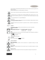
1.2.1 EDITORIAL DIAGRAMS
Service
Refers to situations where you should contact the SERVICE department in the company.
VERINE TECHNICAL SERVICE TECHNICAL PHONE 01787 472551
TECHNICAL FAX 01787 272316
Index
Paragraphs marked with this symbol contain very important information and recommendations, particularly as
regards safety
Failure to comply with them may result in:
- danger of injury to operators
- loss of warranty
- refusal of liability by the producer
Raised Hand
Refers to actions that absolutely must not be performed.
1.2.2 SAFETY DIAGRAMS
Danger of high voltage
Signals that the operation described could cause electrocution if not performed according to the safety
instructions
Generic Danger
Signals that the operation described could cause physical injury if not performed according to the safety
instructions
Danger due to heat
Signals that the operation described could cause burns if not performed according to the safety instructions.

6
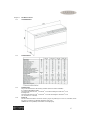
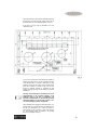
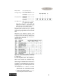
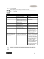
Chapter 1.3 TECHNICAL DATA
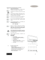
1.3.1 Overall dimensions
1.3.2 Technical features
1.3.3 Technical Notes
The powers indicated refer to the following conditions (ISO 5151 reference standards):
In cooling and dehumidifying mode:
Air entering the inside unit at 27
O
C d.b and 19
O
C w.b with air entering the outside at 35
O
C d.b
In heating mode
Air entering the inside unit at 21
O
C d.b and 19
O
C w.b with air entering the outside at 35
O
C d.b
(d.b = dry bulb w.b = wet bulb)
1.3.4 Proper use
The air-conditioner should be used for the exclusive propose of producing hot or cool air (on demand) for the
sole purpose of obtaining a comfortable temperature in the room.
VERINE will not accept liability if the machine is used improperly.

7
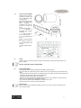
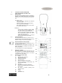
1.4 List of accessories supplied
Packaging units should be
carried by two persons, units
may be stacked three high
for transportation.
The supply includes the parts
listed in the table below.
Before beginning to
assemble the unit, make sure
all parts are within easy
reach.
A- Wall fastening bracket
B - 2 x External air
intake/outlet grids complete
with chains.
C – 2 x tubes to insert into
holes on wall, 50cm long.
D – 2 x Pipe fastening inner
flange 2
E – Kit of screws and anchor
bolts.
F – Manual of instructions
for use and maintenance, and
warranty
G – Paper template to make
holes.
1.4.1 Storage
Store the carton in an enclosed area protected against outside weather conditions and raised off the floor by
planks or a pallet
DO NOT TURN THE CARTON UPSIDE DOWN.
1.4.2 Receipt and unpacking
The packaging is made of suitable material and is packaged by expert personnel.
The units are delivered complete and in perfect condition, however we suggest that you perform the following
checks:-
- On receipt of the cartons check them for any damage and, if found, accept the goods but sign the shippers note
‘damaged’. Keep photographic evidence of any damage found.
- unpack and check the contents against the packing list.
- make sure none of the parts have been damaged during shipment, in case of damage you must report it to us
within 3 days of receipt presenting photographic evidence.
Copy of this notice must be sent to VERINE on fax number 01787 272 316
No claim can be made on Verine after 3 days from delivery.
Important note.
Keep the packaging at least through the warranty period, in case you need to ship the air-conditioner to the
service centre for repair.

8
CHAPTER 2 INSTALLATION.
CHAP 2.1
INSTRUCTIONS FOR INSTALLATION.
To obtain the best results and optimum performance,
follow the instructions for correct installation provided in
this manual. Failure to follow the instructions and apply
the rules indicated may cause malfunction of the appliance
and relieves VERINE of any form of guarantee and
liability for damages to persons, animals or
property.
The electrical system must comply with the regulations
and rating data in the technical sheet, including
an earth connection.
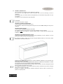
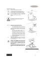
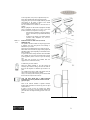
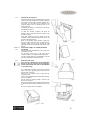
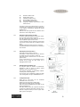
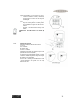
CHAP. 2.2 SELECTION OF POSITION FOR UNIT
The optimum position for the unit is as follows:-
- It is recommended that the bottom of the unit is at
least 2 metres off the floor and no more than 3 (fig 1)
(If the unit is mounted at heights less than 2m avoid siting
it where the cooled air output may cause discomfort to
people nearby).
- The wall on which the unit is installed must be
sturdy and be able to withstand its weight.
- It must be possible to leave room around the unit for
any maintenance operations that may be necessary,
- There should be no obstacles to the free circulation
of air on the intake side and, especially, on the air
outlet side. On this side in particular, there should be
no obstacles closer than 2m.
This could cause turbulence that would interfere with the
correct operation of the unit.
2.2.1 Choice of best position for installing the air conditioner
The air-conditioner must be installed on a wall that
connects to the outside.
Caution: After determining the best place for
installation as described above, check to make sure that
the wall can be drilled at that point without interfering
with other structures or installations (beams, piers,
pipes, wiring, etc.)
Check again to make sure there are no obstacles to air
circulation through the holes drilled due to plants and
their leaves, slats or panelling, blinds, gratings, grids ,
etc).

9
As far as possible, in any case, it is important to try and
reduce major thermal loads by the following means:
Large glass panes exposed to sunlight should be provided
with curtains on the inside or shades on the outside
(Venetian blinds, refracting films, etc)
The air-conditioned room should be closed as much as
possible.
Halogen spotlights or other electrical equipment with high
power consumption should not be used in the room
(toasters, steam irons, hot plates for cooking, etc.).
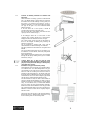
- It should not be installed in a position where the
air flow can strike the people underneath directly
(fig 2).
- It should not be directly over another appliance
(television, radio, refrigerator, etc.), or over a
heat source. (Fig 3).
CHAP 2.3 INSTALLATION OF THE UNIT (Low level)
2.3.1 Drilling the wall
This operation should be carried out using the proper tools
to facilitate your work and prevent excess damage or
disturbance to your client.
The best tools for drilling large holes in walls are special
drills called core borers with very high twisting torque and
adjustable rotation speed depending on the diameter of the
hole to be drilled.
To prevent the creation of large amounts of dust and rubble
due to drilling, the core borer can be fitted with a vacuum
system applied by means of suction cups to the drilling
zone.
Core drills and accessories are available from tool
suppliers to the construction industry.
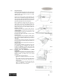
To drill holes, proceed as follows:
Fasten the drilling template to the wall leaving the
necessary space from the ceiling, floor and side walls as
shown on the template. Use adhesive tape to fasten it in
place.
Use a small drill to punch to mark, with extreme care, the
exact centre of each of the holes to be drilled.
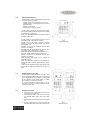
Using a core boring head measuring at least 152mm drill
the two holes for entry and exit of the air.
Note: The holes should have a slight downward
inclination to prevent any backflow of water from the
pipes (see fig 5).
Most of the removed material is expelled outwards,
therefore make sure that it does not hit any person or object
when it falls out.
In order to avoid as much as possible outer plaster
breaking, it is necessary to proceed carefully with the last
part of the hole executing decreasing pressure on the core
borers.

10
Next, drill the holes for anchoring the fastening brackets to
the wall using as a first option the 4 holes on the ends of
the bracket as shown on the drilling template (see fig. 6).
If the wall is not very solid, it is advisable to use some
extra anchor bolts.
As you can see, the bracket can be fastened in a number of
different ways and positions. The air conditioner is heavier
on the left-hand side, so it is best to make sure of a solid
anchorage on that side. The anchor bolts provided require
holes with a diameter of 10mm. In any case, the wall
should be inspected carefully to determine the best
possible anchorage and type of bolts suitable for particular
installations.
Warning: The manufacturer is not liable in the case of
underestimation of the structural integrity of the
anchorage made at the time of installation. We
therefore recommend that you perform this operation
with the maximum care. If not done properly, it can
case serious damage to persons and property.
When installing model equipped with heating pump, if no
drainage well for condensate has been provided built into
the wall (see paragraph 2.3.2), it will be necessary, to
allow drainage of the condensate, to drill a hole through
the wall measuring 16mm in diameter in the position
shown on the template (see fig 6.)

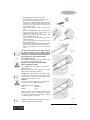
11
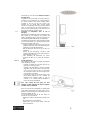
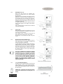
2.3.2 Provision for draining condensate for machines with
heat pump.
When the machine is heating, it produces condensate that
has to be drained through a specific drain line, otherwise
the machine will not work. Drainage occurs by gravity. For
this reason, it is essential for the drain line to have a
minimum inclination of a least 3% throughout its length.
The pipe can be rigid or not, with a minimum internal
diameter of 16mm.
If the line drains into a sewer system, it should be
provided with a trap ahead of the main outlet.
The trap should be at least 300mm lower than the inlet
opening on the air conditioner (fig. 7).
If the drainpipe drains into a vessel (tank or other
container), this container should not be sealed and the
drainpipe should not be immersed in water (see fig.8).
The correct position for the pipe inlet on the machine is
shown on the template for drilling and positioning the
machine (see also fig.6).
The air conditioner is equipped with a pipe with an
external diameter of 14mm for drainage of condensate.
This pipe protrudes from the machine for a length of about
400mm.
The pipe should be fitted inside the one provided by you
for a distance of at least 300mm, without any sharp bends
that would obstruct it.
When draining toward the outside the pipe can be inserted
through the wall (always making sure to give it a suitable
inclination) (see fig.5).
Caution: Make sure, in this case, that the water
expelled outward does not damage or disturb person or
property. During winter time this type of drainage may
cause sheets of ice to form.
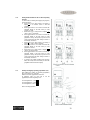
2.3.3 Installation of air pipes and external gratings.
After drilling the holes, the plastic pipes supplied with the
air conditioner have to be fitted through them. The pipe
with insulation on the inside has to be fitted in the right-
hand hole with the insulated part toward the inside as
indicated on the label applied to it. The length of the pipes
should be 55mm less that that of the wall. To cut the pipe a
normal hacksaw can be used. After cutting the pipes fit the
ends into the two internal anchoring flanges (fig,10).
The tubes diameter is nearly the same as those carried out
using the 152mm nominal diameter core drill. In order to
introduce the tubes, they must therefore be forced slightly
using, in most difficult cases, a normal rubber hammer
(fig.10.1). Having the hole internal diameter extremely
similar to the tube external diameter avoids air gaps which
may generate humidity leaks or air noises. Should it prove
difficult to insert then widen the hole slightly using the
drill and core bit.
Next, fit the pipes into the holes in the wall and fasten the
flanges with 4 screws, diameter 6mm, taking care to keep
the two fastening holes in a horizontal position.

12
To position the external grids, proceed as follows:
- Fit the small eyelet of the spring, with the long stem, on
the cap pin (on both connectors) (fig. 10.2).
- Fit the two caps (with spring) from the front part of the
external grid, on the two housings pulling until a click
is heard (fig. 10.3) and attach the two chains to the
large eyelet of the spring.
- Using one hand, grip the two chains connected to the
grid.
- Bend the external grids back, gripping these with your
free hand where the bend is and introducing your
fingers inside the single fins (fig. 10/4).
- Introduce your arm into the pipe until the grid
protrudes completely outwards.
- Allow the grid to reopen, being careful to keep your
fingers inside the fins.
- Turn the grid until the fins are fully horizontal and
tilted towards the outside.
- Pull the chain, tensioning the spring, and fasten the ring
of the chain onto the pin of the inner washer (fig,11).
- Using a pair of nippers, cut the excess chain links
(fig.12).
Warning: If the external grille is accessible , to prevent
the hazards resulting from its possible removal
(insertion of the hands into the pipes and touching the
powered parts), it is absolutely essential to fasten it to
the wall with 4 screws with a diameter of 6mm.
2.3.4
Power supply connection.
The air conditioner is equipped with a power supply cable
for connection to a switched fused outlet.
WARNING: The appliance must be EARTHED.
Refer to rating plate for voltage.
All installations and wiring must be supervised by a
qualified electrician.
Installations and wiring must conform to the current
edition of BS 7671 (IE wiring regulations)
Warning: this appliance must be connected to a double
pole fused (13A) isolating switch which can be switched
off when not in use. Switches should maintain a contact
separation of at least 3mm in all poles.
Important:
The wires in the mains lead fitted to the appliance are
coloured in accordance with the following code:
GREEN AND YELLOW = EARTH
BLUE = NEUTRAL
BROWN = LIVE
Should the mains lead ever require replacement it is
essential that this operation be carried out by a qualified
electrician. It should be replaced with a cable of adequate
size (minimum 1.5mm
2
cross section)
Caution: these operations should be performed with the
machine already positioned on the bracket.

13
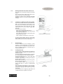
2.3.5 Fitting of the unit on bracket
After checking again that the fastening bracket is securely
fastened to the wall, and that any necessary preparations
for electrical connection and condensate drainage have
been made, you can fasten the air conditioner to its
supporting bracket. Lift it up holding the sides of the
bottom (see fig.13).
To facilitate the operation of fastening it to the bracket,
tilt it slightly toward you.
To make the electrical connection and fasten the
drainpipe, place a wedge between the air conditioner and
the wall. (see fig.14).
After these operations have been carried out the air
conditioner can be pushed firmly against the wall so that
the stud on the bracket catches.
When you are finished inspect carefully to make sure
there are no gaps at the back of the air conditioner (the
insulating gasket must fit firmly against the wall)
particularly in the zone where the air enters and leaves the
machine.
CHAP. 2.4 Preparation for High Level Assembly/Installation
2.4.1 Introduction
The air conditioner is assembled in the factory ready to be
installed low on a wall.
The air outlet, in this case, is at the top of the air
conditioner with the recycle grille and the control panel.
In order to prepare the product for installation on the top
part of the wall follow the instruction below.
2.4.2 Removal of front casing
Note: If the air conditioner has not been installed on
the wall yet, place it on its back. Do not apply heavy
pressure to the bottom of the device as this could dent
or scratch the casing.
Use a small blade screwdriver to remove the horizontal
strips on the casing, applying gentle leverage in the slits
along the sides. (see fig.15).
Take care not to scratch the strips or casing with the
screwdriver point.
Unscrew the 8 self-threading screws that fasten the casing
to the air conditioner.
Lift the casing off carefully, pulling it toward you by
about 50cm (see fig.16).
Disconnect the fastener in the centre that fastens the wires
to the airflow deviation baffle adjustment motor (see fig.
17).
Now you can remove the case completely.

14
2.4.3 Preparation of unit
Unscrew the bracket supporting the small circuit board
with display light and reinstall it on the bottom directly
opposite, where you will find two holes on a small
bracket (see fig. 18-19).
Make sure the connection plate is securely fastened on the
inside of the air conditioner and apply some insulating
tape if necessary. Remove the Styrofoam enclosure on the
lower right-hand side under the air recycle fan and fit it
against the opening above the fan. (see fig.20-21).
When performing this operation place the casing on a
secure surface so not to scratch or dent it. Remove the
plastic plate with the logo and transparent screen for
display light from the control panel by pressing on the
hooks on the rear. Turn it over (rotate by 180
O
) and
reinstall it on the panel.
Reassemble the parts in the opposite position from the
original installation, reversing the air outlet grille with the
control panel grille.
Turn the casing over so that the air outlet grille is on the
lower right-hand side of the device.
Re-connect the plug on the airflow deviation baffle
adjustment motor.
Fit the casing back on the air conditioner carefully, taking
care to hold the wires for the stepper motor to one side so
that they do not interfere with the inner part of the air
outlet grille.
Check that all the couplings on the inside of the case latch
into the rear frame so that the casing fits smoothly and
evenly all around.
Fasten the casing with its eight screws and replace the
strips in their slots.
After completing installation, the electronic parts of the
air conditioner have to be configured so as to take into
account the stratification of heat in the room. This
procedure is outlined in paragraph 2.5 ( Working tests and
identification of possible malfunctions).
CHAP. 2.5 Working Tests and identification of possible
malfunctions.
The program in the microprocessor of this device makes it
possible to run a brief self-test to ensure that the machine
functions normally by starting each of the internal
components,
To run the self-test, proceed as follows:
- Power the air conditioner and make sure it is on stand-
by.
- Use a small screw driver to press the switch located
under the hole on the left of the control panel for at
least 10 seconds.
- At the beginning and end of the self-test procedure the
status of configuration of the machine will be
displayed for a few seconds as follows:

15
Red light (filter): Off = WA210/245 units
On = WHP 210/245 units.
Green light (compr.): Off = with correction of room
temperature.
On = without correction of room
temperature
Orange light (timer): Off = with correction of room
temperature
On = without correction of room
temperature
Green light (power): Off = stand-by in case of black-
out
On = restart in case of black-out
- Check after a few seconds to see whether the
equipment heats normally ( if equipped with a heat
pump function) for about 2 minutes and then, after a
few seconds, that it cools for another 2 minutes.
Before concluding the self-test the electronic part tests
temperature probes to make sure they are operating
normally. If any of these should not be working, the
corresponding signal light remains lit for 20sec. (see table
below).
Should there be any obstruction or fault in the air
conditioner system the indicator panel will display one of
the lights codes shown in the table below. Please be ready
to tell the Service Centre which lights are flashing in
order that a diagnosis can be made.
Starting from the left:
The end of the self-test will be signaled by all the LEDs
lighting up at once and blinking ten times, as well as by
an acoustic signal.
At this time, you can adjust the temperature reading on
the room temperature sensor. This connection is
important if the air conditioner is installed high on the
wall in a room where the warm air tends to stratify
upward (as in rooms with high ceilings or other sources of
heat besides the air conditioner). The sensor will read a
temperature 3
O
C lower than the effective one, in this case,
to compensate for the difference between the lower
inhabited part of the room and the temperature at the
height of the sensor.
1. Check the status of the machine as described
previously, and if no correction has been made,
press the button on the console while the acoustic
signal is on at the end of the self-test.
2. To remove the correction, press the button while
the acoustic signal is on at the end of the test.

16
The machine is set in the factory without correction of
the temperature.
In addition to the self-test (that can be made under any
conditions of room temperature) we recommend that you
also test the product in the various operating modes
accessible to the user (see the user section). One
important test you should make concerns regular
evacuation of condensation water on the models with heat
pump. To check this, keep the machine running for at
least 4-5 hours in heating mode). If the water does not
drain, there should be an “overflow” alarm.
2.5.1 Evacuation of condensation water in case of
emergency.
If there should be a malfunction in the condensation water
drain system, the air conditioner stops working and
signals, with flashing orange, green and red lights ( the
seconds and third LEDs from the left), the alarm status.
To enable the air conditioner to work temporarily until the
service personnel arrives, you can drain the water out by
following these simple instructions:
- Grasp the rubber cap on the bottom centre of the air
conditioner behind the edge of the frame facing the
wall between your thumb and forefinger.
- Pull the rubber tube closed by the cap out by a few
centimeters.
- Remove the cap after placing a bucket or other
container underneath it (at least five litre capacity) to
collect the water (see fig, 23).
- After eliminating the malfunction the service
personnel will take care of closing the evacuation
tube.
CHAP 2.6 Periodic maintenance
Air conditioners of this type do not require any particular
routine maintenance except:
- Cleaning or washing the room filter when the red
light comes on (see user section)
- Cleaning of air inlet radiator, to be done as needed,
depending on the amount of dirt in the external air,
once or twice per year. To do this, you must isolate
the unit and then remove the front casing and the
noise insulation on the inside.
- Cleaning can be done using a vacuum cleaner or soft
brush, taking particular care not to damage the
aluminum heat exchanger baffles. It may be
necessary to use a damp cloth and detergents to
remove any heavily encrusted dirt.
Note: After cleaning the unit replace the noise
insulation carefully matching the edges and gaskets
with their reference markings.
Before you leave the site of installation you should gather
up all packing material and use a damp cloth to remove
and traces of dust that may have been deposited on the
unit during assembly (fig, 24).
To prevent unnecessary calls by the user, before you
leave the site it is a good idea to:
- Explain the contents of the Instruction Manual to the
user.
- Show him/her how to clean the filter.
- Explain when and how he/she should contact the
Service Department.

17
CHAPTER 3 USE AND MAINTENANCE (for the user)
CHAP. 3.1 Important Recommendations
Installation and connection of the air conditioner should
be carried out by a qualified or competent person.
The Instructions for installation are provided in the earlier
sections.
No structural object (furniture, curtains, plants, leaves,
blinds, etc.) should ever obstruct the normal flow of air
from either the internal or external grille.
Never lean or sit on the casing of the air conditioner as
this could cause serious damage to the external parts.
Do not turn the horizontal airflow baffles by hand.
Always use the remote control to adjust the baffle
position.
If the unit leaks water switch it off immediately and
disconnect it from the mains.
Call VERINE TECHNICAL SERVICE
Phone 01787 472551
Fax 01787 272316
When the air conditioner is heating it has to periodically
eliminate any ice that could form on the air outlet
radiator. While it is doing this the machine keeps running
but does not heat the room. This lasts for a brief period of
time, from 3 to a maximum of 10 minutes.
The air conditioner must not be installed in rooms where
excessive gasses develop or where there are conditions of
heat and humidity beyond the maximum limits indicated
in the installation section.
Clean the air filter periodically, as described in the
specific paragraph.
3.2 Names of Parts
3.2.1 List of Units
1. Air outlet grille.
2. Louvres for lateral adjustment of airflow.
3. Motor-operated air baffles for upward airflow.
4. Alarm display console.
5. Air intake grille.
6. Grips for removal of air filter.
7. Rubber hose with cap on end for evacuation of
condensation water in case of emergency.
8. Power cable.
3.2.2 Description of signal console.
1. Remote control lens.
2. Green LED indicating machine is running (When the
machine is on stand-by this light is off).
3. Orange LED indicates on/off programming is in use.
4. Green LED indicates cooling compressor is on.
5. Red LED indicates air filter is clogged.
6. Service switch (RESET).

18
3.3 CONTROLS OF AIR CONDITIONER
USING THE REMOTE CONTROL UNIT
3.3.1 Remote Control
The remote control supplied with the air conditioner is
designed to be extremely sturdy and to ensure excellent
performance in use, but it should always be handled with
care.
For example, do not:
- Leave it out in the rain, spill liquids on its keyboard
or drop it in a liquid.
- Subject it to impacts or drop it onto hard surfaces.
- Leave it exposed to direct sunlight.
- Place obstacles between the remote control and the
air conditioner while using it.
Furthermore:
- If other devices operated by remote control
(TV, radio, stereo, etc.) are located in the same
room as the unit, there may be interference.
- Electronic and florescent lighting may interfere
with communications between the remote
control and the air conditioner.
- Remove the batteries in case of prolonged
periods of disuse of the remote control.
3.3.2 Insertion of batteries
Use only two dry cell batteries type LR03 with 1.5 v
(supplied with the remote control unit). Dispose of used
batteries according to local authority regulations.
Replace both batteries at the same time.
To insert the batteries remove the spring-latch cover on
the back of the remote control.
The batteries have to be inserted according to the
positive and negative pole markings in the bottom of the
battery compartment.
Close the spring-latch cover after inserting batteries.
3.4 REMOTE CONTROL
The remote control is the interface between the user and
the air conditioner. It is therefore particularly important
to familiarize yourself with the parts of the remote
control that relate to this interface.
3.4.1 Description of the remote control
T1 On/Off
T2 Well being mode (Automatic)
T3 Night well being mode
T4 Operating mode selector
T5 Fan speed selector
T6 Button for setting timer and programs.
T7 Button for increasing (+) and decreasing (-) the
temperature/time setting
T8 Not Used.
T9 Movable baffle adjustment On/Off button
D Display: shows operating status and settings as
they are made
D1 Fan speed or automatic operating mode
indicator (AUTO)
D2 Heating
D3 Cooling
D4 Dehumidifier only

19
D5 External air intake switch
D6 Night operation switch
D7 Automatic operation switch
D8 First operating program switch
D9 Second operating program switch
D10 Temperature indicator (thermometer) or time
indicator( H M)
The remote control is also equipped with a cover with a
cursor that can be positioned so as to only permit access
to the ON/OFF, AUTOMATIC MODE and NIGHT
MODE buttons.
With the cover in this position the air conditioner can be
used but none of the settings altered.
3.4.2 Switching on and control of operation
In order to operate the machine via the remote control,
the power to the unit should be switched on.
Once this operations have been carried out, the machine
may be regulated using the remote control.
To send commands to the air conditioner, point the front
of the remote control toward the air conditioner control
panel.
The device emits a beep when it receives a command.
The maximum distance for transmission of commands is
about 8 metres.
3.4.3 Switching the unit on and off (T1)
This button turns the machine on and off.
The machine’s control system has a memory, therefore
any setting will not be lost when it is turned off.
This button serves to switch the unit on or off for brief
periods of time.
In case of prolonged non use of the machine it must be
switched off by turning the main switch off or
unplugging from the mains.
3.4.4 Well being mode (Automatic) (T2)
By using this button the machine is automatically
regulated in order to create an optimal comfort
temperature in the air-conditioned room.
The machines temperature is automatically regulated
according to the rooms temperature.
The fan speed is also automatically regulated according
to the set temperature (except in dehumidification use).
3.4.5 Cooling function (T4)
When used in this mode, the air conditioner
dehumidifies and cools the room.
Button T4 is used to select the op erating mode.
Press until the snowflake appears on the display.
First set the desired temperature and fan speed (see the
relative paragraphs)(T7)
After three minutes (max), the compressor should start
up and the air conditioner should start cooling the room.
When the compressor starts you will see a green LED
light up on the control panel.

20
3.4.6 Dehumidifier only (T4)
When used in this mode, the air conditioner only
eliminates the humidity in the room, without changing
the temperature.
This function can be extremely useful between seasons,
particularly on rainy days when the temperature in not
uncomfortable but the excess humidity feels unpleasant,
When used in this mode, the air conditioner ignores the
temperature and fan speed settings, which are not shown
on the display in this case.
To operate in this mode, press the T4 button until the
droplet symbol appears on the display with automatic
ventilation.
In this operating mode it is normal for the air conditioner
to function intermittently.
3.4.7 Fan only (T4)
When used in this mode the air conditioner does not act
on either the temperature or humidity in the room, but
only keeps the air in circulation.
This operating, mode is selected by pressing the T4
button until the fan symbol appears on the display.
At this stage you can select the fan speed ( see parag
3.4.10)
3.4.8 Heating function (Selected models only)
When used in this mode the air conditioner heats the
room. This function is only available on models with a
heating pump (WHP210 & WHP245).
To select this mode press the T4 button until the sun
symbol appears on the display. First set the desired
temperature and fan speed(T7) (see specific paragraphs).
After three minutes (max) the compressor should start
and the air conditioner begins to heat the room. When
the compressor starts you will see a green LED light up
on the control panel.
Note: The air conditioner has to defrost its condenser
periodically (about once every half hour). During this
operation (3-8 mins) the air conditioner does not heat
the room, though its internal parts remain on except
for the room air fan. When the outdoor temperature
is very low, there may be a slight delay (about three
minutes) for passage from the minimum to the
medium or maximum speed from when the command
is sent to the machine.
3.4.9 Control of airflow direction.(T9)
The airflow can be controlled in both its horizontal and
vertical direction. Control of the horizontal direction
cannot be carried out by the remote control and must be
made manually by adjusting the position of the fins on
the outlet opening.
IMPORTANT: Adjustment of the horizontal airflow
should only be made when the movable grille is not
moving.
Page is loading ...
Page is loading ...
Page is loading ...
Page is loading ...
Page is loading ...
Page is loading ...
Page is loading ...
Page is loading ...
-
 1
1
-
 2
2
-
 3
3
-
 4
4
-
 5
5
-
 6
6
-
 7
7
-
 8
8
-
 9
9
-
 10
10
-
 11
11
-
 12
12
-
 13
13
-
 14
14
-
 15
15
-
 16
16
-
 17
17
-
 18
18
-
 19
19
-
 20
20
-
 21
21
-
 22
22
-
 23
23
-
 24
24
-
 25
25
-
 26
26
-
 27
27
-
 28
28


Verine 91154AA Installation Manual And Instructions For Use
- Category
- Split-system air conditioners
- Type
- Installation Manual And Instructions For Use
Ask a question and I''ll find the answer in the document
Finding information in a document is now easier with AI
Other documents
-
Ames 2445800 Installation guide
-
Argoclima Magico 9.2 Operating instructions
-
TECHNIBEL Ulisse 13 Eco R32 Operating instructions
-
Argo Over Operating instructions
-
 Seville Classics WEB628 Assembly Instructions
-
 George Kovacs P266-1-084-L User manual
-
Trotec PAC 4600 Operating instructions
-
 Andrews Dehumidification HD 500 DV Operating Instructions & Safety Manual
-
 COLZER CFT4.0D User manual
-
Fantini Cosmi X-UNITED-A Owner's manual


