Boss Audio Systems MZ-N1 User manual
- Category
- Car audio amplifiers
- Type
- User manual
This manual is also suitable for

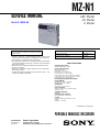
SERVICE MANUAL
PORTABLE MINIDISC RECORDER
AEP Model
UK Model
E Model
SPECIFICATIONS
MZ-N1
US and foreign patents licensed from Dolby
Laboratories.
– Continued on next page –
Model Name Using Similar Mechanism NEW
Mechanism Type MT-MZN1-171
Optical Pick-up Name LCX-5R
Ver 1.0 2002. 01
9-873-443-01 Sony Corporation
2002A0500-1 Personal Audio Company
C 2002.1 Published by Sony Engineering Corporation
•OpenMG, “MagicGate”, “MagicGate Memory Stick”, “Memory Stick”,
VAIO,MusicClip and their logos are trademarks of Sony Corporation.
•“WALKMAN” is a trademark of Sony Corporation.
•Microsoft,Windows,Windows NT and Windows Media are trademarks
or registered trademarks of Microsoft Corporation in the United States
and/or other countries.
•IBM and PC/AT are registered trademarks of International Business
Machines Corporation.
•Macintosh is a trademark of Apple Computer,Inc.in the United States
and/or other countries.
•All other trademarks are trademarks of their respective owners. ™ and
® marks are omitted in this manual.
Audio playing system
MiniDisc digital audio system
Laser diode properties
Material: GaAlAs
Wavelength: λ = 790 nm
Emission duration: continuous
Laser output : less than 44.6 µW
(This output is the value measured at a distance
of 200 mm from the lens surface on the optical
pick-up block with 7 mm aperture.)
Recording and playback time (when
using MDW-80)
Maximum 160 min. in monaural
Maximum 320 min. in stereo
Revolutions
382 rpm to 2,700 rpm (CLV)
Error correction
ACIRC (Advanced Cross Interleave Reed
Solomon Code)
Sampling frequency
44.1 kHz
Sampling rate converter
Input: 32 kHz/44.1 kHz/48 kHz
Coding
ATRAC (Adaptive TRansform Acoustic
Coding)
AT R AC 3 — LP2/LP4

2
MZ-N1
SAFETY-RELATED COMPONENT WARNING!!
COMPONENTS IDENTIFIED BY MARK 0 OR DOTTED
LINE WITH MARK 0 ON THE SCHEMATIC DIAGRAMS
AND IN THE PARTS LIST ARE CRITICAL TO SAFE
OPERATION. REPLACE THESE COMPONENTS WITH
SONY PARTS WHOSE PART NUMBERS APPEAR AS
SHOWN IN THIS MANUAL OR IN SUPPLEMENTS PUB-
LISHED BY SONY.
Modulation system
EFM (Eight to Fourteen Modula tion)
Frequency response
20 to 20,000 Hz ± 3 dB
Wow and Flutter
Below measurable limit
Inputs1)
MIC: stereo mini-jack
(minimum input level 0.25 mV)
Line in:
stereo mini-jack for anolog input
(minimum input level 49 mV)
optical (digital) mini-jack for optical
(digital) input
Outputs
i/LINE OUT
2)
: stereo mini-jack (dedicated
remote control jack)/194 mV (10 kohm )
Maximum output (DC) 2)
Headphones: 5 mW + 5 mW (16 ohm)
Power requirement
Sony AC Power Adaptor connected at the DC
IN 3V jack (country model in parentheses):
220 V AC, 50/60 Hz (Continental Europe)
230 - 240 V AC, 50 Hz (U.K. and Hong
Kong)
100 - 240 V AC, 50/60 Hz (Other countries)
Battery life
1)
When recording2)
(Unit: approxi.hours)(JEITA3))
Batteries SP
Stereo LP2
Stereo LP4
Stereo
Nickel metal
hydride
rechargeable
battery4)
12 17 21
LR6 (SG)
Sony alkaline
dry battery 5)
12 19 23
Nickel metal
hydride
rechargeable
battery 4)
+ One LR6
(SG)5)
30 43 52
The recorder:
Nickel metal hydride rechargeable battery
NH-14WM(A) 1.2V 135 0 mAh (MIN) Ni-
MH
LR6 (SG) alkaline battery
USB cradle:
AC power adaptor DC 3V
Dimensions
Approx. 77.7 × 71.4 ×16.4 mm (w/h/d)
(3
1
/
8
× 2
7
/
8
×
21
/
32
in.)
Mass
Approx. 87 g (3.0 oz) the recorder only
1)
The LINE IN (OPT) jack is used to connect
either a digital (optical) cable or a line
(analog) cable.
2)
The i/LINE OUT jack connects either
headphones/earphones or a line cable.
Design and specitications are subject to change
without notice.
Supplied accessories
AC power adaptor (1)
Headphones/earphones with a remote control (1)
Optical cable (1)
USB cable (1)
Nickel metal hydride rechargeable
battery NH-14WM(A) (1)
CD-ROM (1)*
Dry battery case (1)
Rechargeable battery carrying case (1)
Carrying pouch/carrying case with a belt clip (1)
*Do not play a CD-ROM on an audio CD player.
1)
The battery life may be shorter due to operating
conditions and the temperature of the location.
2)
When you record , use a fully charged
rechargeable battery.
Recording time may
differ according to the alkaline batteries.
3)
Measured in accordance with the JEITA (Japan
Electronics and Information Technology
Industries Association) standard.
4)
When using a 100% fully charged
nickel
metal hydride
rechargeable battery (NH-
14WM(A)).
5)
When using a Sony LR6 (SG) “STAMINA”
alkaline dry battery (produced in Japan).
When playing
(Unit
Batteries SP
Stereo LP2
Stereo LP4
Stereo
Nickel metal
hydride
rechargeable
battery2)
30 38 42
LR6 (SG)
Sony alkaline
dry battery 3)
44 52 62
Nickel metal
hydride
rechargeable
battery2)
+ One LR6
(SG)3)
79 95 110
1)
Measured in accordance woth the JEITA
(Japan Electronics and Information
Technology Industries Association) standard.
2)
When using a 100% fully charged
nickel
metal hydride
rechargeable battery (NH-
14WM(A)).
3)
When using a Sony LR6 (SG) “STAMINA”
alkaline dry battery (produced in Japan)
: approxi.hours)(JEITA1))

3
MZ-N1
TABLE OF CONTENTS
1. SERVICING NOTES............................................... 4
2. GENERAL ................................................................... 5
3. DISASSEMBLY
3-1. Disassembly Flow ........................................................... 6
3-2. Bottom Panel Assy .......................................................... 7
3-3. Upper Panel Section........................................................ 7
3-4. LCD Module, Upper Panel Assy .................................... 8
3-5. MAIN Board Section ...................................................... 8
3-6. Battery Case Assy, MAIN Board.................................... 9
3-7. MD Mechanism Deck (MT-MZN1-171),
Chassis Assy.................................................................... 9
3-8. OP Service Assy (LCX-5R)............................................ 10
3-9. Holder Assy ..................................................................... 11
3-10. DC Motor (Sled) (M602) ................................................ 11
3-11. DC SSM18B Motor (Spindle) (M601),
DC Motor (Over Write Head UP/DOWN) (M603) ....... 12
4. TEST MODE.............................................................. 13
5. ELECTRICAL ADJUSTMENTS......................... 19
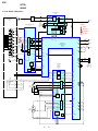
6. DIAGRAMS
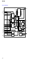
6-1. Block Diagram – SERVO/USB Section –...................... 30
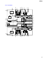
6-2. Block Diagram – AUDIO Section –............................... 31
6-3. Block Diagram – DISPLAY/KEY CONTROL/
POWER SUPPLY Section –........................................... 32
6-4. Note for Printed Wiring Board and
Schematic Diagrams ....................................................... 33
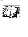
6-5. Printed Wiring Board
– MAIN Board (Component Side) –............................. 34
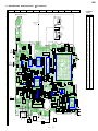
6-6. Printed Wiring Board
– MAIN Board (Conductor Side) –............................... 35
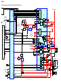
6-7. Schematic Diagram – MAIN Board (1/4) –.................. 36
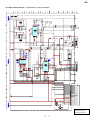
6-8. Schematic Diagram – MAIN Board (2/4) –.................. 37
6-9. Schematic Diagram – MAIN Board (3/4) –.................. 38
6-10. Schematic Diagram – MAIN Board (4/4) –.................. 39
6-11. IC Pin Function Description ........................................... 46
7. EXPLODED VIEWS
7-1. Upper Panel Section........................................................ 53
7-2. Bottom Panel Section...................................................... 54
7-3. Chassis Section ............................................................... 55
7-4. MAIN Board Section ...................................................... 56
7-5. MD Mechanism Deck Section (MT-MZN1-171) .......... 57
8. ELECTRICAL PARTS LIST ............................... 58
CAUTION
Use of controls or adjustments or performance of procedures
other than those specified herein may result in hazardous ra-
diation exposure.
Notes on chip component replacement
•Never reuse a disconnected chip component.
•Notice that the minus side of a tantalum capacitor may be dam-
aged by heat.
Flexible Circuit Board Repairing
•Keep the temperature of the soldering iron around 270 ˚C dur-
ing repairing.
•Do not touch the soldering iron on the same conductor of the
circuit board (within 3 times).
•Be careful not to apply force on the conductor when soldering
or unsoldering.
UNLEADED SOLDER
Boards requiring use of unleaded solder are printed with the lead-
free mark (LF) indicating the solder contains no lead.
(Caution: Some printed circuit boards may not come printed with
the lead free mark due to their particular size)
: LEAD FREE MARK
Unleaded solder has the following characteristics.
•Unleaded solder melts at a temperature about 40 ˚C higher than
ordinary solder.
Ordinary soldering irons can be used but the iron tip has to be
applied to the solder joint for a slightly longer time.
Soldering irons using a temperature regulator should be set to
about 350 ˚C .
Caution: The printed pattern (copper foil) may peel away if the
heated tip is applied for too long, so be careful!
•Strong viscosity
Unleaded solder is more viscous (sticky, less prone to flow) than
ordinary solder so use caution not to let solder bridges occur
such as on IC pins, etc.
•Usable with ordinary solder
It is best to use only unleaded solder but unleaded solder may
also be added to ordinary solder.
On power sources
•Use house current, nikel metal hydride
rechargeable battery, LR6 (SG) battery, or car
battery.
•
For use in your house: For the supplied battery
charging stand, use the AC power adaptor
supplied with this recorder. Do not use any other
AC power adaptor since it may cause the recorder
to malfunction.
Polarity of the
plug

4
MZ-N1
NOTES ON HANDLING THE OPTICAL PICK-UP
BLOCK OR BASE UNIT
The laser diode in the optical pick-up block may suffer electro-
static break-down because of the potential difference generated
by the charged electrostatic load, etc. on clothing and the human
body.
During repair, pay attention to electrostatic break-down and also
use the procedure in the printed matter which is included in the
repair parts.
The flexible board is easily damaged and should be handled with
care.
NOTES ON LASER DIODE EMISSION CHECK
Never look into the laser diode emission from right above when
checking it for adjustment. It is feared that you will lose your sight.
NOTES ON HANDLING THE OPTICAL PICK-UP BLOCK
(LCX-5R)
The laser diode in the optical pick-up block may suffer electro-
static break-down easily. When handling it, perform soldering
bridge to the laser-tap on the flexible board. Also perform mea-
sures against electrostatic break-down sufficiently before the op-
eration. The flexible board is easily damaged and should be handled
with care.
OPTICAL PICK-UP FLEXIBLE BOARD
SECTION 1
SERVICING NOTES
• In performing the repair with the power supplied to the set, re-
moving the MAIN board causes the set to be disabled.
In such a case, fix a convex part of the open/close detect switch
(S804 on MAIN board) with a tape in advance.
Handle the FLEXIBLE board (overwrite head) with care, as it
has been soldered directly to the MAIN board.
In repairing the component side of MAIN board, connect the
FLEXIBLE board (overwrite head) and the MAIN board with
the lead wires in advance. (See page 8)
laser-tap
upper panel assy
MAIN boar
d
Tape
S804
FLEXIBLE board
(Over write head)
• Replacement of CXD2677-202GA (IC801) used in this set re-
quires a special tool.
• The shipment data will be cleared when the NV is reset. There-
fore, change the NV adjusted values following the Change of
NV Adjusted Values immediately after the NV was reset. (See
page 19)
• This set requires the patch data in the nonvolatile memory
(IC802) to be rewritten using the application, when the MAIN
board or nonvolatile memory (IC802) was replaced. (See page
27)
System requirements
• IBM PC/AT or Compatible (The software does not run on Macintosh.)
CPU: MMX™ Pentium® 233 MHz or higher (Pentium® II 400 MHz or higher is
recommended.)
Hard disk drive space: 60 MB or more (The amount of necessary space depends on
the version of the Windows OS or the size of your audio files.)
RAM: 64 MB or higher (128 MB or higher is recommended for Windows® XP Home
Edition/Windows® XP Professional.)
CD-ROM drive (capable of digital playback by WDM)
Sound Board
USB port (supports USB 2.0 Full Speed (previously USB 1.1))
• Operating System: Windows® 98/Windows® 98 Second Edition/Windows® 2000
Professional/Windows® Me/Windows® XP Home Edition/Windows® XP
Professional (manufacturer installed)
The NTFS format of Windows® 2000 Professional, Windows® XP Home Edition, or
Windows® XP Professional (manufacturer-installed) is supported only when used
with the standard (factory) settings.
This software is not supported by the following environments.
– Windows® 95, Windows® NT, or other versions of Windows® NT (such as Server)
– An environment that is an upgrade of the original manufacturer-installed
operating system, as in the following examples:
Windows® 3.1/Windows® 95 t Windows® 98 (or Windows® 98 Second Edition/
Windows® Me)
Windows® Me/Windows® 2000 Professional t Windows® XP
– Multi-boot environment with Windows® 2000 (or Windows® XP) and Windows®
98 (or Windows® 98 Second Edition/Windows®Me)
• Display: High (16bit) Color or more (800 × 480 dot or more)
• Internet access: for Web registration and EMD services
• Windows Media Player (version 7.0 or higher) installed for playing WMA files.
Notes
• Trouble-free operation is not assured within a multiple-monitor environment.
• We do not assure trouble-free operation for all computers satisfying the system requirements.
• Trouble-free operation is not guaranteed following the self-conducted upgrade of home-built
PCs or operating systems.
• We do not assure trouble-free operation of the system suspend, sleep, or hibernation function on
all computers.
• For details, refer to “Net MD Help” of the online help.
Note
The optical digital output connector (on computers provided with one) may be disabled
during playback for the protection of copyrights.
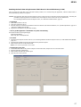
Notes on using OpenMG Jukebox with Windows
2000/Windows XP
If your computer is Windows 2000 Professional, Windows XP Home Edition, or
Windows XP Professional, please be aware of the following before instaling OpenMG
Jukebox.
1 With Windows 2000 Professional, you must log on as “Administrators” (or with the
user name “Administrator”) to install OpenMG Jukebox.
2With Windows XP Home Edition or Windows XP Professional, you must log on
with user name “Computer Administrator” to install OpenMG Jubebox. To check
whether a user name has the attribute of “Computer Administrator” or not, go to
[Control Panel] - [User Account].
Notes on using OpenMG Jukebox with Windows XP/
Windows Me
If Windows XP/Windows Me is installed in your computer, and you perform the
“System Restore” function of the Windows “System Tools,” the songs managed by
OpenMG Jukebox may become corrupted and rendered unplayable.
Therefore, before executing “System Restore,” back up the songs using “OpenMG
Jukebox Backup Tool” first.
Then, after the “System Restore” function is finished, restore the songs using
“OpenMG Jukebox Backup Tool” to ensure the integrity and reliability of song
playback.
For more information about backup, refer to the online Help for OpenMG Jukebox.
Note
When songs become unplayable by executing “System Restore,” an error dialog box may be
displayed. In this case, follow the displayed messages.

5
MZ-N1
SECTION 2
GENERAL This section is extracted from
instruction manual.
12
Looking at controls
The recorder
AEND SEARCH button
BDisplay window
CVOLUME +/– buttons
The VOLUME + button has a tactile dot.
DBattery compartment
ET MARK button
FHOLD switch (at the rear)
GTerminals for attaching dry battery
case
HDC IN 3V jack
IUSB cradle connecting jack
JControl bar
•Moves the cursor in the display.
•Other operations
KGROUP/CANCEL button
LOPEN switch
MCharge lamp
NJog dial (MENU/ENTER)
OLINE IN (OPT) jack
J
1
2
3
5
4
6
qj
qk
qh
qd
qa
qf
qg
qs
8
9
7
Operation Function
Press N 1)
1) The N button has a tactile dot.
play/enter
Press . rewind
Press> fast forward
Flip towards X pause
Flip towards x stop
Turn to select Push to enter
13
PMIC (PLUG IN POWER) jack
There is a tactile dot beside the MIC
(PLUG IN POWER) jack.
QREC (record) switch
Ri (headphones/earphones)/LINE
OUT jack
The display window of the recorder
ACharacter information display
Displays the disc and track names,
date, error messages, track numbers,
etc.
BGroup indication
CDisc indication
Shows that the disc is rotating for
recording, playing or editing an MD.
DREC indication
Lights up while recording. When
flashing, the recorder is in record
standby mode.
ESYNC (synchro-recording) indication
FPlay mode indication
Shows the play mode (shuffle play,
program play, repeat play, etc.) of the
MD.
GLevel meter
HLP2 (LP2 stereo), LP4 (LP4 stereo),
MONO (monaural) indication
ISound indication
Lights up when Digital Sound Preset
is on.
JBattery indication
Shows approximate battery condition.
KMelody timer indication
1342 56
qa9 q;87
14
The headphones/earphones with a remote control
ADISPLAY button
BPLAY MODE button
CRPT/ENT (repeat/enter) button
DSOUND button
EClip
F X (pause) button
GControl (./N>)
N> : play, AMS, FF
. : REW
Turn or turn and hold to play, fast
forward or rewind.
You can quickly fast forward or
rewind without listening to the
playback sound.
HControl (VOLUME +/–)
Pull and turn to adjust the volume.
IDisplay window
JHOLD switch
Kx (stop) button
May be used as the “Enter” button,
depending on the function.
The display window of the remote control
ATrack number display
BCharacter information display
CDisc indication
DMelody timer indication
EPlay mode indication
FBattery level indication
GREC indication
HSOUND indication
+
–
A B C DE
K
F
IJ
G
H
F
HG
ABCDE

6
MZ-N1 SECTION 3
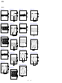
DISASSEMBLY
• This set can be disassembled in the order shown below.
3-1. DISASSEMBLY FLOW
3-2. BOTTOM PANEL ASSY
(Page 7)
3-3. UPPER PANEL SECTION
(Page 7)
SET
3-5. MAIN BOARD SECTION
(Page 8)
3-4. LCD MODULE, UPPER PANEL ASSY
(Page 8)
3-6. BATTERY CASE ASSY, MAIN BOARD
(Page 9)
3-7. MD MECHANISM DECK (MT-MZN1-171),
CHASSIS ASSY
(Page 9)
3-8. OP SERVICE ASSY (LCX-5R)
(Page 10)
3-9. HOLDER ASSY
(Page 11)
3-10. DC MOTOR (SLED) (M602)
(Page 11) 3-11. DC SSM18B MOTOR
(SPINDLE) (M601),
DC MOTOR (OVER WRITE
HEAD UP/DOWN) (M603)
(Page 12)

7
MZ-N1
Note: Follow the disassembly procedure in the numerical order given.
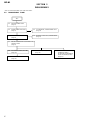
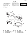
3-2. BOTTOM PANEL ASSY
S801
1
Open the battery
case lid.
4
Close the battery terminal (plus).
6
Remove the bottom panel assy
in the direction of arrow
A
.
knob (hold)
3
Remove the battery
case lid.
2
claw
A
Note : On installation, adjust the position of
both switch (S801) and knob (hold).
5
two screws
(M1.4)
5
three screws (M1.4)
3-3. UPPER PANEL SECTION
6
upper panel section
4
1
flexible board (CN801)
2
Slide the lever (open) in the direction of the arrow,
and open the upper panel section.
3
two screws (M1.4)
3
two screws (M1.4)
5
two convex holes
for screws

8
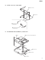
MZ-N1
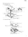
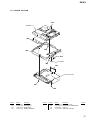
3-4. LCD MODULE, UPPER PANEL ASSY
3-5. MAIN BOARD SECTION
1
four screws (1.7)
3
upper panel section
2
Remove the LCD module
in the direction of the arrow.
1
Remove two solders of the
flexible board (over write head).
2
flexible board (motor) (CN502)
6
flexible board (optical pick-up) (CN501)
7
holder (terminal)
5
3
four screws (M1.4)
8
main board section
4
screw
(M1.4)

9
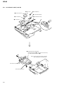
MZ-N1
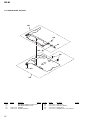
3-6. BATTERY CASE ASSY, MAIN BOARD
3-7. MD MECHANISM DECK (MT-MZN1-171), CHASSIS ASSY
2
battery case assy
3
main boar
d
1
Remove the solder of
terminal (plus).
1
Remove the solder of
terminal (minus).
2
boss
4
spring (POP)
5
chassis assy
1
screw (M1.4)
1
screw
(M1.4)
3
MD mechanism deck (MT-MZN1-171)
2
boss

10
MZ-N1
3-8. OP SERVICE ASSY (LCX-5R)
4
rack spring
3
screw (M1.4)
1
washer (0.8-2.5)
2
gear (SA)
5
screw (M1.4)
6
thrust detent spring
8
Pull off lead screw.
7
over write head section
OP service assy (LCX-5R)
9
Opening the over write head
toward the direction
A
, remove the OP service assy
(LCX-5R) toward the direction
B
.
A
B
Note: Do not open the entire assy forcibly,
when opening the over write head.

11
MZ-N1
3-9. HOLDER ASSY
3-10. DC MOTOR (SLED) (M602)
5
Remove the holder assy
in the direction of arrow
D
.
2
Push the convex portion toward the
direction
B
and open the holder assy
toward the direction
A
to erect uprightly.
3
Remove the concave portion
in the direction of arrow
C
.
4
convex portion
1
Open the holder assy.
A
B
C
D
2
washer (0.8-2.5)
5
DC motor (sled) (M602)
4
two screws (M1.4)
3
gear (SA)
1
Remove six solders
of the motor flexible board.

12
MZ-N1
3-11. DC SSM18B MOTOR (SPINDLE) (M601), DC MOTOR (OVER WRITE HEAD UP/DOWN) (M603)
4
three screws
(M1.4)
6
two screws (M1.4)
9
screw
(M1.2
×
1.5)
qs
gear chassis assy
q;
gear (HA)
gear (HA)
8
gear (HB)
3
gear (HC)
7
washer (0.8-2.5)
2
washer (0.8-2.5)
1
Remove six solders of
the motor flexible board.
qa
DC motor
(over write head up/down)
(M603)
5
DC SSM18B motor
(spindle) (M601)
2.65mm
gear chassis assy
DC motor
(over write head up/down)
(M603)
Note : Press-fit the gear (HA) up to the
position of the DC motor (over write
head up/down) (M603) as shown below.

13
MZ-N1
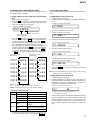
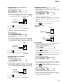
Operation in Setting the Test Mode
• When the test mode becomes active, first the display check mode
is selected.
• Other mode can be selected from the display check mode.
• When the test mode is set, the LCD repeats the following dis-
play.
Remote commander LCD display
•When the Xkey is pressed and hold down, the display at that
time is held so that display can be checked.
Releasing the Test Mode
For test mode set with the method 1:
Turn off the power and open the solder bridge on SL801 (TEST)
on the MAIN board.
Note: Remove the solders completely. Remaining could be shorted with
the chassis, etc.
For test mode set with the method 2 or 3:
Turn off the power.
888
001 V1.000
Microcomputer
version
display
All off
All lit
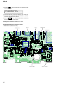
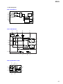
C510
C511
R842
R841
C509
FB802
FB801
C821
C818
C813
C850
C820
+
C810
+
195 199 178 174 170 166 164 158 1
203 180 176 172 168 162 160 1
175 171 169 167 163 159 1
197193
191189
185187
173 179 177 201 165 161 1183182
207 181184186
215 188209190
SL506
SL801
(TEST)
SL801
(TEST) S801
[HOLD]
switch
OFF
t
ON (HOLD)
– MAIN Board (Conductor Side) –
2In the normal mode, turn on the [HOLD] switch. While press-
ing the [VOLUME --] key press the following order:
>t>t.t.t>t
.t > t.tXtX
3In the normal mode, turn on the [HOLD] switch. While
pressing the x/CHG key, press the keys on the remote
commander with the following order:
N > tN > t.t.tN > t
.t N > t.tXtX
Note: If electrical adjustment (CD and MO overall adjustment) has not
been finished completely, “NV Error” is displayed on LCDs of the
set and the remote commander.
SECTION 4
TEST MODE
Outline
• This set provides the Overall adjustment mode that allows CD
and MO discs to be automatically adjusted when in the test mode.
In this overall adjustment mode, the disc is discriminate between
CD and MO, and each adjustment is automatically executed in
order. If a fault is found, the system displays its location. Also,
the manual mode allows each individual adjustment to be auto-
matically adjusted.
• Operation in the test mode is performed with the set. A key
having no particular description in the text, indicates a set key.
• For the LCD display, the LCD on the remote commander is
shown, but the contents of LCD display on the set are same.
Setting Method of Test Mode
There are three different methods to set the test mode:
1Short SL801 (TEST) on the MAIN board with a solder bridge
(connect pin <zvn of IC801 to the ground) and turn on the [HOLD]
switch. Then, turn on the power.

14
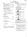
MZ-N1
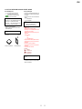
Configuration of Test Mode
Manual Mode
Mode to adjust or check the operation of the set by function.
Normally, the adjustment in this mode is not executed.
However, the Manual mode is used to clear the memory, power
supply adjustment, and laser power check before performing
automatic adjustments in the Overall Adjustment mode.
• Transition method in manual mode
1. Set the test mode (see page 13).
2. Press the >or[VOLUME +] key activates the manual mode
where the LCD display as shown below.
3. During each test, the optical pick-up moves outward or in-
ward while the >or .key is pressed for several sec-
onds respectively.
4. Each test item is assigned with a 3-digit item number;
100th place is a major item, 10th place is a medium item, and
unit place is a minor item.
The values adjusted in the test mode are written to the
nonvolatile memory (for the items where adjustment was
made).
Press the
x/CHG key
[Manual Mode]
[Servo Adjustment]
[Audio Adjustment]
[Power Supply Adjustment]
[OP Alignment Adjustment]
[Overall Adjustment Mode]
[Sound Skip Check Result Display Mode]
[Key Check Mode]
[Test Mode $Display Check Mode%]
Press the
x/CHG key
Press the
. or [VOLUME --] key
Press the
N or [REC] key
Press the
> or [VOLUME +] key
[Electrical Offset Adjustment]
Power Supply Adjustment
Auto Item Feed
CD Overall Adjustment/
MO Overall Adjustment
[Self-Diagnosis Result Display Mode]
Turn the jog dial (down),
or press the
[DISPLAY]
key on the remote commander
Press the
[T MARK]
key, or
[DISPLAY]
key
on the remote commander for several
seconds (about 3 seconds)
The key check quits, or open the upper panel
Press the
x/CHG key
Press the
x/CHG key
x/CHG key
x/CHG key
[VOLUME +] key: 100th place of item
number increase.
[VOLUME --] key: 100th place of item
number decrease.
[Major item switching]
[VOLUME +] key: 10th place of item
number increase.
[VOLUME --] key: 10th place of item
number decrease.
[VOLUME +] key: Increases the adjusted
value of the 1st digit
[VOLUME --] key: Decreases the adjusted
value of the 1st digit
[Medium item switching]
N
key
N
key
[Minor item switching]
[Adjusted value variation]
X key: When adjusted value is
changed:
Adjusted value is written.
When adjusted value is
not changed:
That item is adjusted
automatically.
[Adjusted value write]
> key: Unit place of item number
increase.
. key:Unit place of item number
decrease.
[PLAY MODE] key of
the remote commander:
Increase the adjusted value
of the 2nd digit
[SOUND] key of the remote commander:
Decrease the adjusted value
of the 2nd digit
Remote commander LCD display
Manual
000

15
MZ-N1
Self-Diagnosis Result Display Mode
This set uses the self-diagnostic function system in which if an
error occurred during the recording or playing, the mechanism
control block and the power supply control block in the
microcomputer detect it and record its cause as history in the
nonvolatile memory.
By checking this history in the test mode, you can analyze a fault
and determine its location.
Total recording time is recorded as a guideline of how long the
optical pickup has been used, and by comparing it with the total
recording time at the time when an error occurred in the self-
diagnosis result display mode, you can determine when the error
occurred.
Clear both self-diagnosis history data and total recording time, if
the optical pickup was replaced.
• Self-diagnosis result display mode setting method
1. Set the test mode (see page 13).
2. In the display check mode, turn the jog dial (down) or press the
[DISPLAY] key on the remote commander activates the self-
diagnosis result display mode where the LCD display as shown
below.
3. Then, each time the >key is pressed, LCD display descends
by one as shown below. Also, the LCD display ascends by one
when the .key is pressed.
If the jog dial (down) is turned or the [DISPLAY] key on remote
commander is pressed with this display, the LCD switches to the
simple display mode.
4. Quit the self-diagnosis result display mode, and press the x/
CHG key to return to the test mode (display check mode).
5. The display changes a shown below each time the jog
dial (down) is turned or the [DISPLAY] key on the remote
commander is pressed.
However in the power mode (item number 700’s), only the
item is displayed.
6. Quit the manual mode, and press the x/CHG key to return to
the test mode (display check mode).
Overall Adjustment Mode
Mode to adjust the servo automatically in all items.
Normally, automatic adjustment is executed in this mode at the
repair.
For further information, refer to “SECTION 5 ELECTRICAL
ADJUSTMENTS” (see page 19).
item numberaddress adjusted value
item number
jitter value adjusted value
item number
block error
value adjusted value
item number
ADIP error
value
Focus drive
value
adjusted value
item number adjusted value
item numberitem title adjusted value
• Address & Adjusted Value Display
Remote commander LCD display
• Jitter Value & Adjusted Value Display
Remote commander LCD display
C68S01
011
• Block Error Value & Adjusted Value Display
Remote commander LCD display
• ADIP Error Value & Adjusted Value Display
Remote commander LCD display
• Focus Drive Value & Adjusted Value Display
Remote commander LCD display
• Item Title Display
Remote commander LCD display
063B01
011
059A01
011
015F01
011
OFFJ01
011
LrefPw 01
011
Remote commander LCD display
history code
Total recording time
when error occurred
error display code
1 0000
0XX
0XX 1 ****
0XX N ****
0XX N1****
0XX N2****
0XX R_****
1
1
XX
: Error code
****
: Total recording time

16
MZ-N1
• Description of indication history
History code number Description
1 The first error
N The last error
N1 One error before the last.
N2 Two errors before the last.
R_ Total recording time
Reset the Error Display Code
After servicing, reset the error display code.
• Setting method of reset the error display code
1. Set the test mode (see page 13).
2. Turn the jog dial (down) or press the [DISPLAY] key on the
remote commander activates the self-diagnosis result display
mode.
3. To reset the error display code, press the Xkey (twice) when
the code is displayed (except “R_****”).
(All the data on the 1, N, N1, and N2 will be reset)
• Description of error indication codes
Problem Indication code Meaning of code Simple display Description
No error 00 No error --- No error
01 Illegal access target Adrs Attempt to access an abnormal address
address was specified
Servo system error 02 High temperature Temp High temperature detected
03 Focus error Fcus Disordered focus or can not read an address
04 Spindle error Spdl Abnormal rotation of disc
TOC error 11 TOC error TOC Faulty TOC contents
12 Data reading error Data Data could not be read at SYNC
Power supply system error 22 Low battery LBat Momentary interruption detected
31 Offset error Ofst Offset error
32 Focus error ABCD ABCD Focus error ABCD offset error
offset error
Offset system error 33 Tracking error TE Tracking error Offset error
Offset error
34 X1 tracking error X1TE X1 tracking error Offset error
Offset error

17
MZ-N1
Jog and Key Check Mode
This set can check if the set and remote commander function nor-
mally.
• Setting method of jog check mode
1. Set the test mode (see page 13).
2. Press the jog button to activate the jog check mode and display as
below.
3. Turn the jog dial downwards one click.
4. Turn the jog dial downwards three more clicks.
5. Turn the jog dial upwards one click.
6. Turn the jog dial upwards three more clicks.
7. When the x/CHG key is pressed, it changes over to the key
check mode.
Note: To enter the key check mode, it is not necessary to enter via the jog
dial check mode. (Refer to next item)
• Setting method of key check mode
1. Set the test mode (see page 13).
2. Press the [T MARK] key or [DISPLAY] key on the remote com-
mander for several seconds (about 3 seconds) activates the key
check mode. (At the last two digits, AD value of remote com-
mander key line is displayed in hexadecimal)
3. When each key on the set and on remote commander is pressed,
its name is displayed on the remote commander LCD. (The
operated position is displayed for 4 seconds after the slide
switch is operated. If any other key is pressed during this dis-
play, the remote commander LCD switches to its name dis-
play)
Sound Skip Check Result Display Mode
This set can display the count of errors that occurred during the
recording/playing for checking.
• Setting method of sound skip check result display
mode
1. Set the test mode (see page 13).
2. Press the Nkey or [REC] key, and the playing or recording
sound skip result display mode becomes active respectively
where the LCD displays the following.
3. When the Nkey is pressed, total error count is displayed on
the LCD, and each time the >key is pressed, the display
item moves down by one as shown below. Also, if the .key
is pressed, the display item moves up by one, then if the [REC]
key is pressed, the display in the record mode appears.
When the [REC] key is pressed, total error count is displayed
on the LCD, and each time the >key is pressed, the display
item moves down by one as shown below. Also, if the .key
is pressed, the display item moves up by one, then if
the Nkey is pressed, the display in the play mode appears.
• Cause of sound skip error
Cause of error Description of error
EIB Sound error correction error
Play Stat Decoder status error
Adrs Address access error
BEmp Buffer is empty
BOvr Buffer is full, and sounds were
dumped
Record Bful Buffer capacity becomes less,
and forcible writing occurred
Rtry Retry times over
4. To quit the sound skip check result display mode and to return
to the test mode (display check mode), press the x/CHG key.
Remote commander LCD display
Total count of play
system errors (hex.)
Total count of record
system errors (hex.)
P**R**
000
000 P**R**
000 EIB **
000 Stat**
000 Adrs**
000 BEmp**
000 ######
000 P**R**
000 BOvr**
000 Bful**
000 Rtry**
000 ######
P**R**
: Total play/record errors (hex.)
**
: Counter of sound skip check each item (hex.)
######
: 6-digit address where sound was skipped last (hex.)
Playing sound skip
result display Recording sound skip
result display
Remote commander LCD display
PUSH
000
Remote commander LCD display
JOG+ 1
000
Remote commander LCD display
JOG+OK
000
Remote commander LCD display
JOG- 1
000
Remote commander LCD display
JOG OK
000
Remote commander LCD display
**
000
**
: AD value of the remote commander key
(hexadecimal 00 to FF)

18
MZ-N1
Example1: When the >key on the set is pressed:
Example2: When the N >key on the remote commander
is pressed:
4. When all the keys on the set and on the remote commander are
considered as OK, the following displays are shown for 4 sec-
onds.
Example1: When the keys on the set are considered as OK:
Example2: When the keys on the remote commander are con-
sidered as OK:
5. When all keys were checked or if the upper panel is opened,
the key check mode quits and the test mode (display check
mode) comes back.
Remote commander LCD display
**
: AD value of the remote commander key
(hexadecimal 00 to FF)
FF **
000
Remote commander LCD display
**
: AD value of the remote commander key
(hexadecimal 00 to FF)
rPLAY **
000
Remote commander LCD display
**
: AD value of the remote commander key
(hexadecimal 00 to FF)
SET OK **
888
Remote commander LCD display
**
: AD value of the remote commander key
(hexadecimal 00 to FF)
RMC OK **
888

19
MZ-N1
SECTION 5
ELECTRICAL ADJUSTMENTS
Outline
• In this set, automatic adjustment of CD and MO can be per-
formed by entering the test mode.
However, before starting automatic adjustment, the memory
clear, power supply adjustment, and laser power check must be
performed in the manual mode.
• A key having no particular description in the text, indicates a
set key.
• For the LCD display, the LCD on the remote commander is
shown, but the contents of LCD display on the set are same.
Precautions for Adjustment
1. Adjustment must be done in the test mode only.
After adjusting, release the test mode.
2. Use the following tools and measuring instruments.
• Test CD disc TDYS-1
(Part No. : 4-963-646-01)
• SONY MO disc available on the market
• Digital voltmeter
• Laser power meter LPM-8001
(Part No. : J-2501-046-A)
• Thermometer (using the Temperature Correction)
3. Unless specified otherwise, supply DC 3V from the DC IN
3V jack (J601).
4. Switch position
HOLD switch ............................................... ON
Adjustment Sequence
1. NV Reset (EEPROM clear) Manual Mode
r
2. Power Supply Manual Adjustment Manual Mode
r
3. Temperature Correction (item number: 015)
rManual Mode
4. Laser Power Check
r
5. Electrical Offset Adjustment
Caution: This adjustment must be made with
no disc loaded.
rOverall Mode
6. CD Overall Adjustment
r
7. MO Overall Adjustment
rManual Mode
8. RESUME Clear
Note: If the version of the microcomputer is 1.000 or later, “3. Tempera-
ture Correction” and “2. Power Supply Manual Adjustment” can
be performed continuously in reverse order with pressing the [PLAY
MODE] key on the remote commander in the overall adjustment
mode.
NV Reset
Caution: The shipment data will be cleared when the NV is reset.
Therefore, change the NV adjusted values following the
Change of NV Adjusted Values immediately after the
NV was reset.
Change the NV adjustment values according to the mi-
crocomputer version.
• Setting method of NV reset
1. Select the manual mode of the test mode, and set item number
021 NV Reset (see page 14).
2. Press the Xkey.
3. Press the Xkey once more.
4. Press the x/CHG key to quit the manual mode, and return
the test mode (display check mode).
• Change of NV adjusted values (version 1.000)
Caution: Change the NV adjustment values according to the mi-
crocomputer version.
In this set, some adjusted values were set in the manual mode at
the shipment, but these will be cleared when the NV is reset. There-
fore, modify the NV adjusted values through the following proce-
dure immediately after the NV was reset.
1. Item numbers in which the NV adjusted values are to be modi-
fied
– Change ABCD gain [Hpit] initial value (item number 336)
Caution:The ABCD gain [Hpit] initial value must be
changed before the overall adjustment.
– Change DFTC threshold value (item number 151)
– Turn off sound generation speed-up (item numbers 861 to
864)
– Change CLV drive voltage limiter (item numbers 865, 866)
– Change x2 CLV speed gain, +6dB compared to conventional
(item numbers 867, 868)
– Change x2 CLV phase gain, +3dB compared to conventional
(item numbers 871, 872)
– Change x2/x1 switching temperature threshold value
(+10°C t +5°C) (item numbers 873, 874)
Remote commander LCD display
NV reset (after several seconds)
Res***
021
Reset!
021
Remote commander LCD display
ResNV CC
021
Remote commander LCD display
ResOK?
021

20
MZ-N1
2. NV adjusted values modifying procedure
1) Select manual mode of the test mode, and set item number
336 (see page 14).
2) Adjust with the [VOLUME +] key (adjusted value up) or [VOL-
UME --] key (adjusted value down) so that the adjusted value
becomes 8.
3) Press the Xkey to write the adjusted value.
4) Select manual mode of the test mode, and set item number
149 (see page 14).
5) Press the >key to set item number 151.
6) Adjust with the [VOLUME +] key (adjusted value up) or [VOL-
UME --] key (adjusted value down) so that the adjusted value
becomes 07.
7) Press the Xkey to write the adjusted value.
8) Select manual mode of the test mode, and set item number
861 (see page 14).
9) Adjust with the [VOLUME +] key (adjusted value up) or [VOL-
UME --] key (adjusted value down) so that the adjusted value
becomes 79.
10) Press the Xkey to write the adjusted value.
11) Select manual mode of the test mode, and set item number
862 (see page 14).
12) Adjust with the [VOLUME +] key (adjusted value up) or [VOL-
UME --] key (adjusted value down) so that the adjusted value
becomes 00.
13) Press the Xkey to write the adjusted value.
14) Select manual mode of the test mode, and set item number
863 (see page 14).
15) Adjust with the [VOLUME +] key (adjusted value up) or [VOL-
UME --] key (adjusted value down) so that the adjusted value
becomes EA.
16) Press the Xkey to write the adjusted value.
17) Select manual mode of the test mode, and set item number
864 (see page 14).
18) Adjust with the [VOLUME +] key (adjusted value up) or [VOL-
UME --] key (adjusted value down) so that the adjusted value
becomes 01.
19) Press the Xkey to write the adjusted value.
20) Select manual mode of the test mode, and set item number
865 (see page 14).
21) Adjust with the [VOLUME +] key (adjusted value up) or [VOL-
UME --] key (adjusted value down) so that the adjusted value
becomes 2C.
22) Press the Xkey to write the adjusted value.
23) Select manual mode of the test mode, and set item number
866 (see page 14).
24) Adjust with the [VOLUME +] key (adjusted value up) or [VOL-
UME --] key (adjusted value down) so that the adjusted value
becomes B9.
25) Press the Xkey key to write the adjusted value.
26) Select manual mode of the test mode, and set item number
867 (see page 14).
27) Adjust with the [VOLUME +] key (adjusted value up) or [VOL-
UME --] key (adjusted value down) so that the adjusted value
becomes C9.
28) Press the Xkey to write the adjusted value.
29) Select manual mode of the test mode, and set item number
868 (see page 14).
30) Adjust with the [VOLUME +] key (adjusted value up) or [VOL-
UME --] key (adjusted value down) so that the adjusted value
becomes 80.
31) Press the Xkey to write the adjusted value.
32) Select manual mode of the test mode, and set item number
871 (see page 14).
33) Adjust with the [VOLUME +] key (adjusted value up) or [VOL-
UME --] key (adjusted value down) so that the adjusted value
becomes CA.
34) Press the Xkey to write the adjusted value.
35) Select manual mode of the test mode, and set item number
872 (see page 14).
36) Adjust with the [VOLUME +] key (adjusted value up) or [VOL-
UME --] key (adjusted value down) so that the adjusted value
becomes 2D.
37) Press the Xkey to write the adjusted value.
Remote commander LCD display
**
: Adjusted value
V1 dat **
862
Remote commander LCD display
**
: Adjusted value
V2 num **
863
Remote commander LCD display
**
: Adjusted value
V3 dat **
864
Remote commander LCD display
**
: Adjusted value
V3 num **
865
Remote commander LCD display
**
: Adjusted value
V3 dat **
866
Remote commander LCD display
**
: Adjusted value
V4 num **
867
Remote commander LCD display
**
: Adjusted value
V4 dat **
868
Remote commander LCD display
**
: Adjusted value
V5 num **
871
Remote commander LCD display
**
: Adjusted value
V5 dat **
872
Remote commander LCD display
**
: Adjusted value
AbcdGn **
336
Remote commander LCD display
**
: Adjusted value
Dfct 1 **
151
Remote commander LCD display
**
: Adjusted value
V1 num **
861
Page is loading ...
Page is loading ...
Page is loading ...
Page is loading ...
Page is loading ...
Page is loading ...
Page is loading ...
Page is loading ...
Page is loading ...
Page is loading ...
Page is loading ...
Page is loading ...
Page is loading ...
Page is loading ...
Page is loading ...
Page is loading ...
Page is loading ...
Page is loading ...
Page is loading ...
Page is loading ...
Page is loading ...
Page is loading ...
Page is loading ...
Page is loading ...
Page is loading ...
Page is loading ...
Page is loading ...
Page is loading ...
Page is loading ...
Page is loading ...
Page is loading ...
Page is loading ...
Page is loading ...
Page is loading ...
Page is loading ...
Page is loading ...
Page is loading ...
Page is loading ...
Page is loading ...
Page is loading ...
Page is loading ...
Page is loading ...
Page is loading ...
Page is loading ...
-
 1
1
-
 2
2
-
 3
3
-
 4
4
-
 5
5
-
 6
6
-
 7
7
-
 8
8
-
 9
9
-
 10
10
-
 11
11
-
 12
12
-
 13
13
-
 14
14
-
 15
15
-
 16
16
-
 17
17
-
 18
18
-
 19
19
-
 20
20
-
 21
21
-
 22
22
-
 23
23
-
 24
24
-
 25
25
-
 26
26
-
 27
27
-
 28
28
-
 29
29
-
 30
30
-
 31
31
-
 32
32
-
 33
33
-
 34
34
-
 35
35
-
 36
36
-
 37
37
-
 38
38
-
 39
39
-
 40
40
-
 41
41
-
 42
42
-
 43
43
-
 44
44
-
 45
45
-
 46
46
-
 47
47
-
 48
48
-
 49
49
-
 50
50
-
 51
51
-
 52
52
-
 53
53
-
 54
54
-
 55
55
-
 56
56
-
 57
57
-
 58
58
-
 59
59
-
 60
60
-
 61
61
-
 62
62
-
 63
63
-
 64
64


Boss Audio Systems MZ-N1 User manual
- Category
- Car audio amplifiers
- Type
- User manual
- This manual is also suitable for
Ask a question and I''ll find the answer in the document
Finding information in a document is now easier with AI