
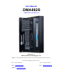
DMA882S Digital Stepper Drive User Manual
Table of Contents
1.Introduction......................................................................................................................................................................1
1.1 Features...................................................................................................................................................................1
1.2 Applications............................................................................................................................................................ 1
2.Specifications....................................................................................................................................................................2
2.1 Electrical Specifications......................................................................................................................................... 2
2.2 Environment............................................................................................................................................................2
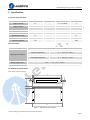
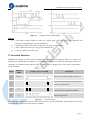
2.3 Mechanical Specifications......................................................................................................................................2
2.4 Elimination of Heat.................................................................................................................................................3
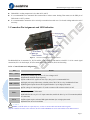
3. Connection Pin Assignments and LED Indication...................................................................................................... 3
3.1 P1 - Control Connector Configurations..................................................................................................................3
3.2 P2 - Fault Output Connector...................................................................................................................................4
3.3 P3 - Motor and Power Connector...........................................................................................................................4
3.4 P4 - Tuning Port......................................................................................................................................................4
3.5 Status LED Lights...................................................................................................................................................4
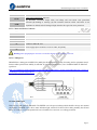
4. Control Signal and Fault Output.................................................................................................................................. 5
4.1 Control Signal Connection..................................................................................................................................... 5
4.2 Fault Output Connection........................................................................................................................................ 5
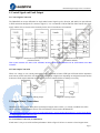
5. Stepper Motor Connections........................................................................................................................................... 5
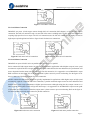
5.1 4-lead Motor Connection (recommended)............................................................................................................. 5
5.2 6-lead Motor Connection........................................................................................................................................6
5.3 8-lead Motor Connection........................................................................................................................................6
6.Power Supply Selection................................................................................................................................................... 7
6.1 Regulated or Unregulated Power Supply............................................................................................................... 7
6.2 Power Supply Sharing............................................................................................................................................ 7
6.3 Selecting Supply Voltage........................................................................................................................................7
7.DIP Switch Configurations............................................................................................................................................. 7
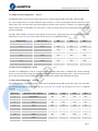
7.1 Output Current Configuration (SW1-3).................................................................................................. 8
7.2 Idle Current Configuration (SW4).................................................................................................. 8
7.3 Micro Step Configuration (SW5-8).................................................................................................. 8
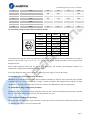
7.4 Auto-tuning and Motor Model Selection (Rotary Switch).....................................................................................9
7.5 Smoothing Filter Time Configuration (ProTuner)................................................................................................. 9
7.6 Activated Pulse Edge Configuration (ProTuner)....................................................................................................9
7.7 Control Mode Configuration (ProTuner)............................................................................................................... 9
8. Wiring Notes..................................................................................................................................................................10
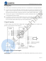
9. Typical Connection....................................................................................................................................................... 10
10. Sequence Chart of Control Signals........................................................................................................................... 10
11. Protection Functions................................................................................................................................................... 11
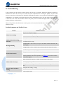
12. Troubleshooting...........................................................................................................................................................12
13. Warranty......................................................................................................................................................................13


 1
1
 2
2
 3
3
 4
4
 5
5
 6
6
 7
7
 8
8
 9
9
 10
10
 11
11
 12
12
 13
13
 14
14
 15
15
 16
16


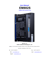 Leadshine EM882S User manual
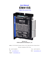 Leadshine EM415S User manual
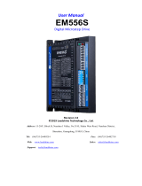 Leadshine EM556S User manual
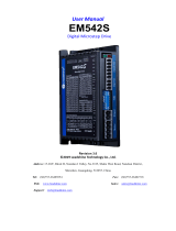 Leadshine EM542S User manual
 Leadshine DMA860E User manual
 Leadshine CS1-D507S User manual
 Leadshine DM1182 User manual
 Leadshine DM Series Installation guide
 Leadshine DM442 User manual
 Leadshine iES Installation guide


