Page is loading ...

® U.S. Registered Trademark
Copyright © 1999 Honeywell Inc. • All Rights Reserved
INSTALLATION INSTRUCTIONS
66-1099
Integrated Valve Train
APPLICATION
These Integrated Gas Valve Train component installation
instructions are for small valves (3/4 in. to 2 in.) and large
valves (2 in. to 3 in.) are identical except where noted.
INSTALLATION
When Installing this product...
1. Read these instructions carefully. Failure to follow them
could damage the product or cause a hazardous
condition.
2. Check ratings given in these instructions and on the
product to make sure the product is suitable for your
application.
3. Make sure the installer is a trained, experienced service
technician.
4. Use these instructions to check out product operation
after installation.
WARNING
Fire or Explosion Hazard.
Can cause property damage, serious injury or
death.
Perform the safety shutdown test any time work is
done on a gas system.
Make sure gas is turned off before starting installation.
Bolt Torque Specifications
Torque specifications for the two bolt sizes are:
•3/8 in. 16 bolts: 13 lb-ft.
•1/2 in.-13 bolts: 25 lb-ft.
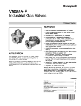
Valve Assembly Precautions (Fig. 1)
1. Use new, properly reamed, pipe, free from chips.
2. Do not thread pipe too far into pipe adapter. Valve
distortion or malfunction can result from excess pipe in
the valve.
3. Do not attach valve actuator until valve body installation
is complete.
4. Make sure O-ring sealing surfaces are clean.
5. Apply moderate amount of good quality pipe dope,
resistant to the action of liquid propane (LP) gas only
on the pipe threads.
6. Make sure the gas flow is in the direction of the arrow
on the gas valve casting.
NOTE: Gas flow in the V4297S Normally Open Vent Valve
can be in either direction.
Fig. 1. Preparing pipes.
Connecting Upstream or Downstream Pipe
Adapter to Valve (Fig. 2)
1. Using the grease packet provided (or equivalent,
general purpose, lithium grease), grease the O-ring.
Make sure the grease is applied evenly around the
entire O-ring.
2. Insert the O-ring into the O-ring groove.
3. Assemble the pipe adapter to the valve using the three
bolts, nuts and lock washers as shown in Fig. 2.
INCORRECT:
CORRECT:
TWO CLEAN
THREADS
WITH
MODERATE
AMOUNT
OF DOPE
EXCESS DOPE CAN BLOCK
DISK FROM
VALVE
SEAT
LOOSE
CHIPS
CORRECT:
NORMAL
FULL
THREAD
REAM PIPE AND BLOW
OUT CHIPS (TO AVOID
LODGING ON SEAT)
TOO LONG,
DISTORTS
VALVE SEAT
TOO LONG,
DISTORTS
VALVE SEAT
M16410
1
1
USE PIPE DOPE RESISTANT TO ACTION OF LP GAS.
INCORRECT:
PIPE
ADAPTER
PIPE
ADAPTER

2
INTEGRATED VALVE TRAIN
66-1099
Fig. 2 Connecting the pipe adapter to the valve.
Connecting V4297S Normally Open Vent
Valve (NOVV) Between Two Valves (Fig. 3)
1. Using the grease packet provided (or equivalent,
general purpose, lithium grease), grease the O-ring of
the first valve. Make sure the grease is applied evenly
around the entire O-ring.
2. Insert the O-ring into the O-ring groove.
3. Assemble the NOVV to the first valve using the three
bolts, nuts and lock washers as shown in Fig. 3.
4. Using the grease packet provided (or equivalent,
general purpose lithium grease), grease the O-ring of
the second valve. Make sure the grease is applied
evenly around the entire O-ring.
5. Insert the O-ring into the O-ring groove.
6. Assemble the NOVV to the second valve using the
three bolts, nuts and lock washers as shown in Fig. 3.
IMPORTANT
All bolts should be pointing out of the NOVV.
Fig. 3. Connecting the normally open vent valve between
two valves.
Connecting Normally Open Vent Valve
Adapter Between Two Valves (Fig. 4)
1. Using the grease packet provided (or equivalent,
general purpose, lithium grease), grease the O-ring of
the first valve. Make sure the grease is applied evenly
around the entire O-ring.
2. Insert the O-ring into the O-ring groove.
3. Assemble the NOVV adapter to the first valve using the
three bolts, nuts and lock washers as shown in Fig. 4.
4. Using the grease packet provided (or equivalent,
general purpose lithium grease), grease the O-ring of
the second valve. Make sure the grease is applied
evenly around the entire O-ring.
5. Insert the O-ring into the greased O-ring groove.
6. Assemble the NOVV adapter to the second valve using
the three bolts, nuts and lock washers as shown in Fig.
4.
NOTE: Use the three smaller bolts provided with the large
NOVV Adapter to connect the downstream side of
the NOVV adapter with the second valve.
IMPORTANT
Be sure that all bolts point out of the NOVV adapter.
GREASE
PACKET
O-RING
PIPE ADAPTER
M16407
O-RING
O-RING
M16402
GREASE
PACKET
GREASE
PACKET
FIRST
VALVE
SECOND
VALVE
V4297
3 BOLTS ON
EACH SIDE
O-RING
O-RING
M16403
SECOND
VALVE
FIRST
VALVE
3 BOLTS ON
EACH SIDE
NOVV ADAPTER
LOCKWASHER
NUT
GAS FLOW
Fig. 4. Connecting the normally open vent valve adapter
between two valves.
Connecting Two Valves in Series (Fig. 5)
1. Using the grease packet provided (or equivalent,
general purpose lithium grease), grease the O-ring of
the first valve. Make sure the grease is applied evenly
around the entire O-ring.
2. Insert the first O-ring into the O-ring groove.
3. Using the grease packet provided (or equivalent,
general purpose lithium grease), grease the O-ring of
the second valve. Make sure the grease is applied
evenly around the entire O-ring.
4. Insert the second O-ring into the O-ring groove.
5. Assemble the first valve to the second valve using the
three bolts, nuts and lock washers as shown in Fig. 5.

INTEGRATED VALVE TRAIN
366-1099
IMPORTANT
Point the top two bolts upstream and the third bolt
downstream when connecting two valves in series.
Connecting a C6097 Pressure Switch to a
Valve (Fig. 6)
1. Remove the 1/4 in. (6 mm) NPT plug from the side of
the valve.
2. Remove the label holding the O-ring in place on the
C6097 and make sure the O-ring seal is in place.
3. Remove the C6097 Cover by removing the cover
screws.
4. Mount the C6097 Pressure Switch on the valve using
the two screws provided.
5. Replace the C6097 Cover.
Fig. 5. Connecting two valves in series.
O-RINGS
M16409
SECOND
VALVE
FIRST
VALVE
GAS FLOW
M16408
VALVE
REMOVE PLUG
(1/4 IN. SOCKET HEAD)
C6097
BODY
C6097
COVER
Fig. 6. Connecting C6097 Pressure Switch to Valve.
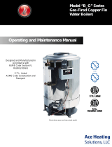
Completing the Assembly (Fig. 7):
1. Assemble the upstream and downstream pipes to the
valve train.
2. Apply a parallel jaw wrench only to the pipe adapter flat
next to the pipe being inserted (Fig. 7). A wrench
applied to the valve body itself, or to the end farthest
from the pipe being inserted, can distort the casting,
causing a malfunction. Do not use the valve as a lever.
3. Make sure the gas flow is in the same direction as the
arrow on the valve body.
4. Paint the pipe adapters and valve train components
with a rich soap and water solution to check for bubbles
that indicate a gas leak at the pipe adapter and valve
mating surfaces.
5. Make sure the power supply is disconnected from the
powered components. Mount the actuators on the valve
bodies and complete the electrical and linkage
connections by following the instructions packed with
the actuators and solenoid valves.
CORRECT:
VISE GRIPS END
NEXT TO PIPE
BEING INSERTED
CORRECT:
WRENCH
CORRECTLY
APPLIED NEXT
TO PIPE BEING
INSERTED INCORRECT:
WRENCH APPLIED
HERE STRAINS
VALVE BODY
M11684
Fig. 7. Completing the valve train.

4
INTEGRATED VALVE TRAIN
66-1099
66-1099 G. R. 4-99 customer.honeywell.com
Automation and Control Solutions
Honeywell International Inc. Honeywell Limited—Honeywell Limitée
1985 Douglas Drive North 35 Dynamic Drive
Golden Valley, MN 55422 Scarborough, Ontario M1V 4Z9
/