Page is loading ...

OPERATOR’S MANUAL
WARNING: OPERATOR MUST READ AND UNDERSTAND THIS MANUAL
COMPLETELY BEFORE OPERATING THIS EQUIPMENT.
©
Tacony Corporation, All rights reserved
Save These Instructions
175 RPM, 1 HP models - C131-7 C171, C201
175 RPM, 1.5 HP models - C171HD, C201HD
Sander, 175 RPM, 1.5 HP models - C171SD
175 - 320 RPM, 1.5 HP models - C202
X8692 11/2018

2
Your new Powr-Flite floor machine will afford you many years of trouble-free operating
satisfaction provided it is given proper care. Prior to packaging, your Powr-Flite floor machine
was inspected by a Quality Control Technician.
UNCRATING
Your Powr-Flite floor machine was protectively packed to prevent damage in shipment. We
suggest that upon removing the unit from its carton, you carefully inspect it for any possible
damage in transit. If damage is discovered, immediately notify the transportation company who
delivered your machine. As a manufacturer, we are unable to act upon any claim for concealed
damage; you must originate the claim.
IMPORTANT SAFEGUARDS
This machine is designed to be safe when used to perform the
functions specified in this Operator’s Manual. Should damage occur to electrical or mechanical
parts, Prior to further use, the machine should be repaired by the manufacturer or competent
service center to avoid further damage to the machine or physical injury to user. Your floor
machine is equipped with a safety switch lockout device designed for your safety. Do not attempt
to bypass or defeat the safety lockout device. Never use any device to lock the power switch
triggers in the ON position.
WARNINGS
WARNING: The operator must have training in the operation of this machine before using
it.
WARNING: Machines can burn flammable materials and vapors. Do not use this machine
with or near fuels, grain dust, solvents, thinners or other flammable materials.
WARNING: Do not operate this machine unless it is completely assembled.
WARNING: Do not use this machine as a step or to move furniture.
WARNING: When disconnecting power cord from electrical outlet, grasp the plug. Pulling
it out by the cord itself can damage cord insulation and internal connection to plug. To
prevent electric shock, always remove the electrical plug from the electrical outlet before
doing any repairs or maintenance to this machine.
WARNING: To prevent injury, always remove the electrical plug from the electrical outlet
before changing the polishing pad and before leaving the machine.
WARNING: To prevent injury, keep hands, feet and loose clothing away from the rotating
pad.
WARNING: Maintenance and repairs must be done by authorized personnel only.
WARNING: Keep all fasteners tight. Keep adjustments according to specifications.
WARNING: Keep the electrical parts of the machine dry. For storage, keep the machine in
a building.
WARNING: Always use a three-wire electrical system connected to the electrical ground.
For maximum protection against electric shock, use a circuit that is protected by a ground
fault circuit interrupter. Consult with your electrical contractor.
WARNING: To prevent damage to the power cord, do not let the pad, pad driver or wheels
touch the power cord when the machine is running. Always lift the power cord over the
machine.
WARNING: Make sure all labels, decals, warning, cautions and instructions are fastened
to the machine.
WARNING: Do not leave machine running unattended.

3
FLOOR MACHINE APPLICATIONS
• Spray buffing with red spray buff pad and spray buff chemical.
•
• Dry buffing a buffable finish with a tan, beige or white pad or brush.
•
• Scrubbing with green or blue pad or scrubbing brush.
•
• Stripping with a black pad and a stripping chemical.
1.5 HP MODELS ON CARPET
• Bonnet cleaning with a yarn bonnet and carpet maintainer chemical.
•
• Shampooing using a showerfeed shampoo brush and solution tank mounted to the handle
tube containing carpet shampoo.
1.5 HP MODELS
• Scraping with an attachment tool to remove heavy industrial deposits and residue or to
prepare a foundation for installation of carpet.
•
• Wire brushing of concrete floors.
•
• Sanding with very aggressive sandpaper or sand screen discs.
•
• Carpet restoration where shampooing & pile lifting require very stiff brush bristles.
This appliance must be grounded. If it should malfunction or breakdown, grounding provides
a path of least resistance for electric current to reduce the risk electric shock. This machine is
equipped with a cord having an equipment -grounding conductor and grounding plug. The plug
must be inserted into an appropriate outlet that is properly installed and grounded in accordance
with all local codes and ordinances.
WARNING: Improper connection of the equipment-grounding conductor can result in a risk
of electric shock. Check with a qualified electrician or service person if you are in doubt as to
whether the outlet is properly grounded. Do not modify the plug provided with the appliance - if it
will not fit the outlet, have a proper outlet installed by a qualified electrician.
This appliance is for use on a nominal 120-volt circuit, and has a grounding plug that looks like
the plug illustrated in sketch A
METAL SCREW
COVER OF GROUNDED
OUTLET BOX
( B )
( A )
GROUNDING PIN
GROUNDING
MEANS
ADAPTER
( C )
A

4
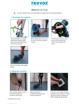
PREPARING THE MACHINE
To attach the drive block or brush or other attachment, be sure the
handle is “locked” in the upright position. Lay the floor machine on its
back with the handle lying on the floor, this exposes the driving plate
on the underside of the floor machine. Holding the drive block, brush
or attachment in both hands and straddling the motor with your back
to the handle box, bend over and fit the three slots of the clutch plate
(build into the back of the brush) over the three lugs of the driving plate.
Turn the drive block, brush or attachment counter-clockwise as far as
it will go until it is seated in the ready-to-use position. CAUTION: This
is the only proper way to install a drive block, brush or attachment.
NEVER put a drive block, brush or attachment on the machine by placing it on the floor and
moving the running machine over it, or by placing the machine over the block or attachment
and then starting the motor. Return the floor machine to upright position and adjust handle to
operating position. Recommended handle position is close to the waist with arms extended
down. Lock the cam release lever into position.
NOTE: The hardened steel cam release lever does not require extreme tightening to effectively
hold the handle in position. Over-tightening will shorten the functional life of the lever. To remove
drive block, brush or attachment: Lay the floor machine on it’s back again and disengage clutch
plate slots from driving plate lugs by turning clockwise.
HOW TO OPERATE THE MACHINE
First install the pad driver and pad, brush or other attachments to
be used. Plug the machine in as directed and lower the handle to
the desired operating height and lock in place using the cam lever
handle. Push the safety switch forward and squeeze the switch triggers
beneath the handle grips. This activates the motor and starts the
block, brush or attachment in operation. Each time you release the triggers the safety switch will
reset. You will need to follow the direction above to restart the machine. CAUTION: When leaving
the machine unattended, disconnect the wall plug and return the handle to the “locked” upright
position to prevent accidental starting.
TO GUIDE YOUR FLOOR MACHINE
To Right: raise handle slightly. The higher the handle is lifted, the faster the machine will move to
the right. To Left: to change direction, lower the handle until the machine travels to the left. The
more the handle is lowered, the faster the movement to the left.
TRANSPORTING THE MACHINE
Place the handle in the upright position. Lock the handle cam release lever. Tip the machine back
and transport on the wheels.
MAINTENANCE
Once a month remove the motor cover and vacuum out any dust or debris which has
accumulated on the motor. Replace the motor cover by setting it over the holes in the housing
and replace all of the screws. Check and maintain the tightness of all the fasteners.
WARNING: Do not over-tighten the switch housing screws.
Keep the machine clean especially at the handle tube and collar so the handle tube will move
freely through the collar. Inspect the cord for cuts, gashes, or loose prongs; replace as needed.
Disassembly of this motor voids the warranty. Improper disassembly and assembly of this motor
can permanently damage the field or rotor.

5
TROUBLESHOOTING
Machine does not run.
• The circuit breaker has tripped. Allow the circuit breaker 2 minutes to cool before resetting.
• Plug is broken or has loose contact. Replace.
Machine will not start.
• Circuit breaker is not reset. Reset breaker.
• Plug is broken or has a loose contact. Replace.
• Circuit breaker is defective or weak. Replace.
• Switch is defective. Replace switch.
Machine will not reach operating speed.
Unplug anything else other than the machine from the circuit or locate another circuit.
Motor runs but pad or brush does not turn.
Coupling is broken. Replace.
Coupling is not covered under warranty. Do not attempt to place a running machine over a block
or brush. Always install and remove the block or brush by hand.
Prevent circuit overload.
Check the pad and change it if it is rough or dirty. Spray buffing or spray cleaning is not a
substitute for scrubbing or mopping a floor. Prepare the floor surface before spray buffing.
Eliminate any extension cord that is smaller than 12/3 wire or greater than 25 feet in length.
Unplug anything other than the machine from the circuit or locate another circuit.

6

7
Ref Part# Description
1 X8911 Handle, All Metal
M8600-3 Handle assembled (includes #1 through #7)
2 X8941 Handle grip 1” diameter
3 X8914 Thumb switch actuator
4 X8927 Label Logo, Metal handle
5 X8923 Insulation sheet 2.5 x 2 x .015
6 F5P Switch 25 amp sp momentary w/nuts
7 X8013 Cord hook, plated
8 X8023 Circuit breaker, 15 amp. C131-7, C171, C201
X8023A Circuit breaker, 17 amp. C171HD, C201HD
9 X8266 Screw 10-32 x 3/4 fmhs ss
10 X8412-C Label 13” 1hp 175 rpm
X8982 Label 17” 1hp 175 rpm
X8983 Label 20” 1hp 175 rpm
X8984 Label 17” 1-1/2hp 175 rpm
X8985 Label 20” 1-1/2hp 175 rpm
X9101 Label dual speed classic C202
11 X8965 Motor cover
12 X8106 Spacer, motor cover, metal floor machines
13 X8265 Screw 1/4-20 x 3/4 flat phillips
14 X8020 Washer, Countersunk, axle
15 X8024 Wheel, black, 5” x 1-1/4”
16 X8101 Washer, spring, 1” OD x 1/2” ID
17 X8980 Motor 1-1/2 hp 120/240v 60hz C171HD, C201HD
X8981 Motor 1 hp 120/240v 60hz C131-7, C171, C201
X8071-TI Motor assembly 2 speed w/ 10:1 gearbox C202
18 X8400A Powr-Flite Label
19 X8966 Motor base, metal
20 X1149
X8967A Brush cover 17” metal w/ bumper
X8968A Brush cover 20” metal w/ bumper
21 X8212 Washer 1/4 med split lock zinc
22 X8218 Washer 5/16 sae flat zinc
23 X8219 Washer 3/8 sae falt zinc
24 72455A Screw 1/4-20 x 1-3/4 hex cap
25 X8977 Pivot pin metal floor machine
26 X9575 Axle, wheel
27 X8107 Spacer, handle, metal floor machine only
28 X8807L Handle brace, left w/ slot
29 X8807R Handle brace, right w/ hole
30 X8989 Cord 14/3 SJTW 51.25 black (in handle)
31 X8016 Knob, plastic, handle clamp
32 X8012 Clamp, collar, handle
33 X1184 Cam lever assembly (includes X8016 and washers)
NOT ILLUSTRATED
X9049 Motor screen 2 speed classic C202
X9050 Motor screen spring 2 speed classic C202
PX7 Toggle switch 20a/125v classic 2 speed C202
PX28 Boot rubber toggle switch C202 classic 2 speed
X8530 2-speed motor control
X8034-2 Rectifier (2-speed machine)
PX7 2-speed toggle switch
MS1369AS Power Cord Assembly STW 14/3 50’

A Tacony Company
3101 Wichita Court • Fort Worth, TX 76140-1755
1-800-880-2913 • Fax: 1-817-551-0719 • www.Powr-Flite.com
X8692 11/2018
Powr-Flite Warranty Statement
All Powr-Flite equipment has been tested and inspected at the factory and is guaranteed
to be free from defects in material and workmanship for the duration described below. For
full details, contact your authorized Powr-Flite Distributor, Service Center, or the Powr-Flite
Technical Service Department.
IMPORTANT WARRANTY CONDITIONS:
Warranty starts from the date of sale to the consumer or, at Powr-Flite’s discretion, six
months after the dealer has purchased the unit from Powr-Flite, whichever comes first.
All non-wear parts purchased after machine warranty expiration are warrantied for one
year. Proof of purchase is required to process all claims. Powr-Flite sales and service
representatives are not authorized to waive, alter, or increase the terms of this warranty.
Warranty DOES NOT cover the following:
• Routine wear and tear items such as brushes, filters, points, plugs, bulbs, switches,
brooms, wheels/tires, casters, fuses, belts, hoses, and sheer pins/motor couplings.
• Damage that occurs during shipping. A claim should be filed directly with the carrier to
collect damages.
• Unauthorized machine modifications or parts not purchased directly from Powr-Flite or an
authorized reseller.
• Failure to properly inspect, maintain, operate, and store the machine. Misuse/abuse is
determined at Powr-Flite’s sole discretion and examples include damage from pressure
washing the machine, exposing the machine to rain, cold, or snow, and damage to the
vacuum motor caused by failure to use defoamer.
• Cleaning and refinishing charges or machine downtime. Rentals and other replacement
machines are not available from Powr-Flite during the repair period.
5 Years - Tanks
2 years - Motors
1 Year - Parts/Labor
/