Page is loading ...

PC-HELPER
No-Isolated RS-232C Micro Converter
for USB2.0
COM-1(USB)H
Isolated RS-232C Micro Converter
for USB2.0
COM-1P(USB)H
User’s Guide
CONTEC CO., LTD.

COM-1(USB)H, COM-1P(USB)H
i
Check Your Package
Thank you for purchasing the CONTEC product.
The product consists of the items listed below.
Check, with the following list, that your package is complete. If you discover damaged or missing
items, contact your retailer.
Product Configuration List
- Micro converter (One of the following)
[COM-1(USB)H + gender changer …1] *1
[COM-1P(USB)H + gender changer …1] *1
- First step guide …1
- COM Setup Disk (Disk *2) …1
- Warranty Certificate …1
- Serial Number Label …1
*1: The converter is packed with the gender changer attached.
*2: The bundled disk contains the driver software and User’s Guide (this guide).
First step guide
First step guide
Serial Number LabelWarranty Certificate
Warranty Certificate
Micro converter Disk

ii
COM-1(USB)H, COM-1P(USB)H
Copyright
Copyright 2013 CONTEC CO., LTD. ALL RIGHTS RESERVED
No part of this document may be copied or reproduced in any form by any means without prior written
consent of CONTEC CO., LTD.
CONTEC CO., LTD. makes no commitment to update or keep current the information contained in this
document. The information in this document is subject to change without notice.
All relevant issues have been considered in the preparation of this document. Should you notice an
omission or any questionable item in this document, please feel free to notify CONTEC CO., LTD.
Regardless of the foregoing statement, CONTEC assumes no responsibility for any errors that may
appear in this document or for results obtained by the user as a result of using this product.
Trademarks
MS, Microsoft, Windows and Windows NT are trademarks of Microsoft Corporation. Other brand and
product names are trademarks of their respective holder.

COM-1(USB)H, COM-1P(USB)H
iii
Table of Contents
Check Your Package .................................................................................................................................... i
Copyright ..................................................................................................................................................... ii
Trademarks .................................................................................................................................................. ii
Table of Contents ....................................................................................................................................... iii
1. BEFORE USING THE PRODUCT 1
About the Product........................................................................................................................................ 1
Features ................................................................................................................................................. 1
Support Software.................................................................................................................................. 2
Customer Support ........................................................................................................................................ 2
Web Site................................................................................................................................................ 3
Limited One-Year Warranty ...................................................................................................................... 3
How to Obtain Service ................................................................................................................................ 3
Liability ........................................................................................................................................................ 3
Safety Precautions ....................................................................................................................................... 4
Safety Information ............................................................................................................................... 4
Handling Precautions ........................................................................................................................... 4
Environment ......................................................................................................................................... 6
Inspection.............................................................................................................................................. 6
Storage .................................................................................................................................................. 6
Disposal ................................................................................................................................................ 6
2. SETUP 7
What is Setup? ............................................................................................................................................. 7
Installing the driver .............................................................................................................................. 7
Step 1 Setting the Hardware ....................................................................................................................... 8
Name of each parts .............................................................................................................................. 8
Step 2 Installing the Software .................................................................................................................... 9
Step 3 Installing the Hardware ................................................................................................................. 10
Connecting the converter .................................................................................................................. 10
Setting with the Found New Hardware Wizard .............................................................................. 11
Windows Vista ................................................................................................................................... 11
Windows XP....................................................................................................................................... 13
Step 4 Initializing the Software ................................................................................................................ 15
Step 5 Checking Operations with the Diagnosis Program ..................................................................... 16
What is the Diagnosis Program?....................................................................................................... 16
Check Method .................................................................................................................................... 16
Using the Diagnosis Program ........................................................................................................... 17
Step 6 Uninstalling the Driver Libraries ................................................................................................. 19

iv
COM-1(USB)H, COM-1P(USB)H
If your problem cannot be resolved ......................................................................................................... 19
3. EXTERNAL CONNECTION 21
Interface connectors .................................................................................................................................. 21
Directly Connecting the Product ...................................................................................................... 21
Connecting the Product with a Cable ............................................................................................... 22
Gender changer .................................................................................................................................. 22
4. FUNCTION 23
Communication Function ......................................................................................................................... 23
Serial Data Transmission .................................................................................................................. 23
RS-232C Control Lines ..................................................................................................................... 23
Setting the Baud Rate ........................................................................................................................ 23
Bus isolation [COM-1P(USB)H] ..................................................................................................... 23
Surge protection [COM-1P(USB)H] ................................................................................................ 23
5. ABOUT HARDWARE 25
LED display ............................................................................................................................................... 25
Hardware specifications ........................................................................................................................... 26
Physical dimension ................................................................................................................................... 27

1. Before Using the Product
COM-1(USB)H, COM-1P(USB)H
1
1.
Before Using the Product
This chapter provides information you should know before using the product.
About the Product
COM-1(USB)H is a micro converter for converting the USB port of PC into RS-232C serial
communications.
COM-1P(USB)H is an isolated micro converter for converting the USB port of PC into RS-232C serial
communications. COM-1P(USB)H is higher noise-resistant models with isolation between a PC and
bus line as well as a surge protection circuit for communication ports.
This product has one channel RS-232C communication port.
These products support a baud rate of up to 921,600bps and has separate 128-byte / 384-byte buffer
memory for transmit and receive. It also comes with a Windows driver, which allows boards to be
used as OS-standard COM ports.
This product supports CONTEC-defined driver library “API-PAC(W32)” that provide local routines.
Features
- Max. 921,600bps RS-232C Serial Communication
This product has one channel RS-232C-standard serial ports. Baud rates from 300 to 921,600 bps can
be set by software. When data is transferred at the high speed, it may not be transferred normally,
depending on the use environment such as the external device and cable length used.
- Compatible to USB1.1/USB2.0 and not necessary to power this product externally as the bus power
is used.
Compatible to USB1.1/USB2.0 and capable to achieve high speed transfer at Full Speed (12Mbps).
Not necessary to power this product externally as the bus power of USB is used.
- Possibly used as Windows-standard COM ports, using the bundled driver library
Comes with a driver software that allows the products to be used under Windows in the same way as
COM ports on the PC. Under Windows, the product supports the OS-standard Win32 API
communication function as well as Visual Basic MSComm. In addition, supplies a diagnostic program
to confirm hardware operation and to perform a communication test with equipment.
- Isolation between channels and between PCs, surge protection for all signal lines
(For COM-1P(USB)H only)
Electric isolation is provided between channels and between PCs. This prevents electric noise between
PCs and external circuits. As surge protection is provided on all signal lines, you can safely use the
products in environments where you are concerned about surges causing incorrect operation or damage
to the PC.

1. Before Using the Product
2
COM-1(USB)H, COM-1P(USB)H
- Max. 127 converters can be installed as configured in the range COM1 - COM256.
Using a USB hub allows you to install up to 127 converters to a single PC.
COM1 - COM256 can be set using the device manager.
- Each channel is equipped with separate 128-byte / 384-byte FIFO buffers for transmit and receive.
These are FIFO format, useful for high speed communications and to reduce the load to the CPU when
transmitting/receiving.
As the device manager can be used to enable/disable the use of FIFO and set the FIFO trigger size, you
can build an optimum system according to your use.
- 9-pin D-SUB connector (female type) can be connected directly to a device such as a modem.
Use of a 9-pin D-SUB connector (female type) allows you to connect it to a device such as a modem
directly. It can also be connected to the cable of another 9-pin D-SUB connector (female type), if the
gender changer is connected. (*Installed before shipment)
- To suit your application, cables and connectors are available as optional
Straight cables (1.8m), cross cables (1.8m) and 9-pin D-SUB connectors (male or female type) for your
own cables are available as optional.
- The control line for RS-232C can be controlled and monitored by software.
The control lines for RTS, CTS, DTR and DSR can be controlled and monitored using software.
Support Software
Standard COM Driver Software
COM Setup Disk
(Bundled)
Under Windows, this software allows you to use the serial ports on the converter as if they were
standard COM ports on the PC. You can add additional micro converters up to a maximum of 127
COM ports.
Under Windows, the serial ports can be accessed using the standard Win32 API communication routines
(CreateFile( ), WriteFile( ), ReadFile( ), and SetCommState( ), etc.) The serial ports are also
compatible with the Visual Basic communication control (MSComm).
* API-SIO(98/PC) is not used.

1. Before Using the Product
COM-1(USB)H, COM-1P(USB)H
3
Customer Support
CONTEC provides the following support services for you to use CONTEC products more efficiently
and comfortably.
Web Site
Japanese http://www.contec.co.jp/
English http://www.contec.com/
Chinese http://www.contec.com.cn/
Latest product information
CONTEC provides up-to-date information on products.
CONTEC also provides product manuals and various technical documents in the PDF.
Free download
You can download updated driver software and differential files as well as sample programs available in
several languages.
Note! For product information
Contact your retailer if you have any technical question about a CONTEC product or need its price,
delivery time, or estimate information.
Limited One-Year Warranty
CONTEC products are warranted by CONTEC CO., LTD. to be free from defects in material and
workmanship for up to one year from the date of purchase by the original purchaser.
Repair will be free of charge only when this device is returned freight prepaid with a copy of the
original invoice and a Return Merchandise Authorization to the distributor or the CONTEC group
office, from which it was purchased.
This warranty is not applicable for scratches or normal wear, but only for the electronic circuitry and
original products. The warranty is not applicable if the device has been tampered with or damaged
through abuse, mistreatment, neglect, or unreasonable use, or if the original invoice is not included, in
which case repairs will be considered beyond the warranty policy.
How to Obtain Service
For replacement or repair, return the device freight prepaid, with a copy of the original invoice. Please
obtain a Return Merchandise Authorization number (RMA) from the CONTEC group office where you
purchased before returning any product.
* No product will be accepted by CONTEC group without the RMA number.
Liability
The obligation of the warrantor is solely to repair or replace the product. In no event will the
warrantor be liable for any incidental or consequential damages due to such defect or consequences that
arise from inexperienced usage, misuse, or malfunction of this device.

1. Before Using the Product
4
COM-1(USB)H, COM-1P(USB)H
Safety Precautions
Understand the following definitions and precautions to use the product safely.
Safety Information
This document provides safety information using the following symbols to prevent accidents resulting
in injury or death and the destruction of equipment and resources. Understand the meanings of these
labels to operate the equipment safely.
DANGER indicates an imminently hazardous situation which, if not avoided, will
result in death or serious injury.
WARNING indicates a potentially hazardous situation which, if not avoided, could
result in death or serious injury.
CAUTION indicates a potentially hazardous situation which, if not avoided, may
result in minor or moderate injury or in property damage.
Handling Precautions
Do not use the product where it is exposed to flammable or corrosive gas. Doing so may result in
an explosion, fire, electric shock, or failure.
- Do not strike or bend these products.
Otherwise, these products may malfunction, overheat, cause a failure or breakage.
- Do not touch these product's metal plated terminals (USB connector, D-SUB connector) with your
hands.
Otherwise, these products may malfunction, overheat, or cause a failure.
If these products are touched by someone's hands, clean these products with industrial alcohol.
- Make sure that your PC can supply ample power to all these products installed.
Insufficiently energized products could malfunction, overheat, or cause a failure.
- The specifications of these products are subject to change without notice for enhancement and
quality improvement.
Even when using these products continuously, be sure to read the manual and understand the
contents.
- Do not modify these products. CONTEC will bear no responsibility for any problems, etc.,
resulting from modifying these products.
- Regardless of the foregoing statements, CONTEC is not liable for any damages whatsoever
(including damages for loss of business profits) arising out of the use or inability to use these
CONTEC products or the information contained herein.
- It may cause a trouble in recognizing and operating the device according to the kind of USB hub.
If you use the USB hub, we encourage you to take advantage of the CONTEC’s product loan
service to confirm operation before purchasing.
DANGER
WARNING
C
AUTION
DANGER
CAUTION

1. Before Using the Product
COM-1(USB)H, COM-1P(USB)H
5
- COM-1P(USB)H Regarding “FCC PART 15 Class A Notice”
These products have acquired the above-mentioned standard.
However, a sufficient margin may not be secured for the standard. In this case, use a ferrite core
(SEIWA E04SR301334 or a compatible product) for the COM cable (this product’s side).
When attaching the ferrite core, coil it around once near the connector while leaving it open, and
then close it.
- Regarding “CE EMC Directive Notice”
The ferrite core must be installed in interface connecting cable so that this product may suit the
above-mentioned standard.
Name
Maker
Turn
Quantity
Installation Site
E04SR301334 SEIWA 2 1
on
t
he COM cable at product side and
device’s side
E04SR170730A
SEIWA
1
1
on USB cable at PC side
* Equivalent product can also be used.
Image diagram
FCC PART 15Class A Notice
This equipment has been tested and found to comply with the limits for a Class A digital device,
pursuant to part 15 of the FCC Rules. These limits are designed to provide reasonable protection
against harmful interference when the equipment is operated in a commercial environment.
This equipment generates, uses, and can radiate radio frequency energy and, if not installed and
used in accordance with the instruction manual, may cause harmful interference to radio
communications. Operation of this equipment in a residential area is likely to cause harmful
interference in which case the user will be required to correct the interference at his own expense.
NOTE
FCC WARNING
Changes or modifications not expressly approved by the party responsible for compliance could void
the user's authority to operate the equipment.
Ferrite core
Cable
TURN: 1
TURN: 2
TURN: 3
TURN: 4

1. Before Using the Product
6
COM-1(USB)H, COM-1P(USB)H
Environment
Use this product in the following environment. If used in an unauthorized environment, the board may
overheat, malfunction, or cause a failure.
Operating temperature
0 - 50°C
Operating humidity
10 - 90%RH (No condensation)
Corrosive gases
None
Floating dust particles
Not to be excessive
Inspection
Inspect the product periodically as follows to use it safely.
Storage
When storing this product, keep it in its original packing form.
(1) Put the product in the storage bag.
(2) Wrap it in the packing material, then put it in the box.
(3) Store the package at room temperature at a place free from direct sunlight, moisture, shock,
vibration, magnetism, and static electricity.
Disposal
When disposing of the product, follow the disposal procedures stipulated under the relevant laws and
municipal ordinances.
- The connection part o
f c
onne
cto
r
have no stain or corr
osi
on.

2. Setup
COM-1(USB)H, COM-1P(USB)H
7
2.
Setup
This chapter explains how to set up the converter.
What is Setup?
Setup means a series of steps to take before the product can be used.
Different steps are required for software and hardware.
Installing the driver
This section enables you to prepare the software and hardware by operating in accordance with each
step in this chapter using the bundled disk. Taking the following steps sets up the software and
hardware. You can use the diagnosis program later to check whether the software and hardware
function normally.
Step 1 Setting the Hardware
Step 2 Installing the Hardware
Step 3 Initializing the Software
Step 4 Checking Operations with the Diagnosis Program
If Setup fails to be performed normally, see the “Setup Troubleshooting” section at the end of this
chapter.

2. Setup
8
COM-1(USB)H, COM-1P(USB)H
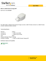
Step 1 Setting the Hardware
This section describes how to setup the converter and connect it to your PC.
Name of each parts
COM-1(USB)H, COM-1P(USB)H
Figure 2.1. Name of each parts
In
te
rf
ace
c
o
nn
ec
t
or
D-
S
U
B
9
p
i
n
(F
e
m
al
e
)
Interf
ace connec
tor
U
SB
T
ype
A

2. Setup
COM-1(USB)H, COM-1P(USB)H
9
Step 2 Installing the Software
Install software.
Run [\USB\Com1Usb\Setup.exe] from the supplied bundled disk
(1)
The screens below show the installation. Click [next].
(2)
Accept the license agreement, then click [Next>].
(3)
The setup is completed

2. Setup
10
COM-1(USB)H, COM-1P(USB)H
Step 3 Installing the Hardware
Under Windows, information about the converter needs to be detected by the OS. This is called
hardware installation.
When using multiple converters, install one at a time and complete setup for the previous
converter before starting to install the next converter.
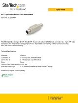
Connecting the converter
(1)
Turn on the power to the PC before connecting the product.
(2)
When the PC has been up and running, plug the USB interface connector to a USB port in the PC.
The converter can also be connected to the PC via a USB hub.
Figure 2.2. Connecting the converter
It may cause a trouble in recognizing and operating the device according to the kind of USB hub.
If you use the USB hub, we encourage you to take advantage of the CONTEC’s product loan
service to confirm operation before purchasing.
U
SB p
ort
s
CAUTION

2. Setup
COM-1(USB)H, COM-1P(USB)H
11
Setting with the Found New Hardware Wizard
Windows Vista
(1)
“Found New Hardware” Wizard is open. Click “Locate and install driver software”.
(2)
When the “Found New Hardware” windows is displayed, insert the accompanying bundled
disk ”COM Setup Disk” into the CD-ROM drive. After a while, the device installation process
begins.

2. Setup
12
COM-1(USB)H, COM-1P(USB)H
(3)
Click “Browse my computer for driver software (advanced)”.
(4)
Click “Next”
You have now finished installing the hardware.

2. Setup
COM-1(USB)H, COM-1P(USB)H
13
Windows XP
(1) The “Found New Hardware Wizard” will be started.
(2) Select “Install from a list or specific location[Advanced]”, then click on the [Next] button.
(3) Specify that folder on the bundled disk which contains the setup information (INF) file to register
the converter.
Source folder is “(CD-ROM drive letter)\USB\COM1USB”.
* Be sure to uncheck [Search removable media (floppy, disk)].
* COM-1(USB)H
or
COM-1P(USB)H
is displayed.

2. Setup
14
COM-1(USB)H, COM-1P(USB)H
(4) In Windows XP, the Hardware Wizard displays the following alert dialog box when you have
located the INF file. This dialog box appears, only indicating that the relevant driver has not
passed Windows Logo testing, and it can be ignored without developing any problem with the
operation of the terminal.
In this case, click on the [Continue Anyway] button.
When completing the installation, push the completion button and close the wizard.
(5) After that, do the same operation so that you can confirm the COM port.
You have now finished installing the hardware.
* COM-1(USB)H
or
COM-1P(USB)H
is displayed.

2. Setup
COM-1(USB)H, COM-1P(USB)H
15
Step 4 Initializing the Software
The COM ports are already assigned by the hardware installation step.
Run Device Manager as described below if you wish to view or modify the COM port settings.
Start Device Manager
(1) Select "System" from "Control Panel" and start [Device Manager].
(2) Make sure that the detected USB device is listed in the "Universal Serial Bus controllers" folder.
(3) Check that the new COM ports are displayed in the [Ports] folder.
Updating the Settings
(1) If you wish to change a port number, open the properties page for the port and click the
[Advanced…] button under [Port Settings].
(2) Use the [COM Port Number] combo box to modify the COM port number.
You have now finished installing the initial setting of Software.
* COM-1(USB)H
or
COM-1P(USB)H
is displayed.
* COM-1(USB)H
or
COM-1P(USB)H
is displayed.
/