3 Instrum
ent selection
VEGAMET 381
The VEGAMET 381 is a universal signal conditioning and indicating in-
strument for simple control tasks in all industries. It is designed for con-
nection of an individual 4 … 20 mA sensor and optionally takes over the
function of a power supply unit.
Via an adjustment, the measured value can be scaled individually and
indicated on the integrated display. The measured value can be also
transferred via the current output to an external indication or a higher-
ranking control system. For control tasks, two operating relays are avail-
able as level signallers for the control of pumps or other actors. The instru-
ment is suitable for rail, front panel and surface mounting.
VEGAMET 391
The VEGAMET 391 is a universal signal conditioning instrument for a
number of control tasks such as level, gauge and process pressure meas-
urement. Inventory management, VMI (Vendor Managed Inventory) and
remote enquiry are additional application possibilities. It is designed for
connection of any 4 … 20 mA sensor and can optionally function as a
power supply unit.
Comprehensive adjustment functions allow an individual adaptation to
the respective application. The measured value can be scaled/linearized
individually and indicated on the integrated display. In addition, the meas-
ured value can be transferred via the current output to an external indica-
tion or higher-ranking control system. For control tasks, six operating
relays are available as level signallers for control of pumps or other ac-
tuators. When the fail safe relay is used, the number of level relays is
reduced to five. The instrument is suitable for carrier rail, front panel
and surface mounting.
On instruments with one of the optionally available interfaces (RS232/
Ethernet), the measured values can be retrieved via modem or network
and displayed through a web browser or WEB-VV. A measured value and
message transmission is also possible via e-mail/SMS.
VEGAMET 624
The VEGAMET 624 is a universal signal conditioning instrument for a
number of control tasks such as level, gauge and process pressure meas-
urement. Inventory management, VMI (Vendor Managed Inventory) and
remote enquiry are additional application possibilities. It is designed for
connection of any 4 … 20 mA sensor and can optionally function as a
power supply unit.
Comprehensive adjustment functions allow an individual adaptation to
the respective application. The measured value can be scaled/linearized
individually and indicated on the integrated display. In addition, the meas-
ured value can be transferred via the current output to an external indica-
tion or higher-ranking control system. For control tasks, three operating
relays are available as level signallers for control of pumps or other ac-
tuators. The instrument is suitable for carrier rail, front panel and surface
mounting.
On instruments with one of the optionally available interfaces (RS232/
Ethernet), the measured values can be retrieved via modem or network
and displayed through a web browser or WEB-VV. A measured value and
message transmission is also possible via e-mail/SMS.
VEGAMET 625
The VEGAMET 625 is a universal signal conditioning instrument for a
number of control tasks such as level, gauge, interface, differential and
process pressure measurement. Inventory management, VMI (Vendor
Managed Inventory) and remote enquiry are further application possibil-
ities. It is designed for connection of two independent HART sensors and
optionallytakes over the function of a power supply unit. Two independent
measurements can be carried out at the same time, a third measurement
loop calculates on request the difference of the two input values.
Comprehensive adjustment functions allow an individual adaptation to
the respective application. The measured values can be scaled/linear-
ized individually and indicated on the integrated display. In addition, the
measured values can be transferred via the current outputs to an external
indication or higher-ranking control system. For control tasks, three oper-
ating relays are available as le vel signallers for control of pumps or other
actuators. The instrument is suitable for carrier rail, front panel and sur-
face mounting.
On instruments with one of the optionally available interfaces (RS232/
Ethernet), the measured values can be retrieved via modem or network
and displayed through a web browser or WEB-VV. A measured value and
message transmission is also possible via e-mail/SMS.
VEGASCAN 693
VEGASCAN 693 is a universal signal conditioning instrument for many
different regulatory and control tasks such a s level, gauge, interface,
differential and process pressure measurement. Inventory management,
VMI (Vendor Managed Inventory) and remote enquiry are the main appli-
cations. It is designed for connection of 15 independent VEGA HART
sensors (5 with Ex applications) and can optionally function as a power
supply unit. Up to 15 (5 with Ex) separate measurements can be carried
out at the same time.
Comprehensive adjustment functions allow an individual adaptation to
the respective application. The measured values can be scaled/linear-
ized individually and shown on the integrated display. The instrument is
suitable for carrier rail and surface mounting.
On instruments with one of the optionally available interfaces (RS232/
Ethernet), the measured values can be retrieved via modem or network
and displayed through a web browser or WEB-VV. A measured value and
message transmission is also possible via e-mail/SMS.
Measured value enquiry/Visualisation/VMI
For visualisation or remote enquiry, the signal conditioning instruments
VEGAMET 391/624/625 and VEGASCAN 693 can be optionally equip-
ped with an RS232 or Ethernet interface. These interfaces are integrated
in the instrument and cannot be retro-installed.
RS232 interface
The RS232 interface is suitable for simple modem connection to
PACTware or WEB-VV. External analogue, ISDN and GSM modems
can be used for this purpose.
Ethernet interface
With the Ethernet interface, the signal conditioning instruments can be
connected directly to an existing PC network. Each instrument gets its
own IP address under which it can be reached from everywhere in the
network. As an alternative, addressing via DHCP and network name is
also possible.
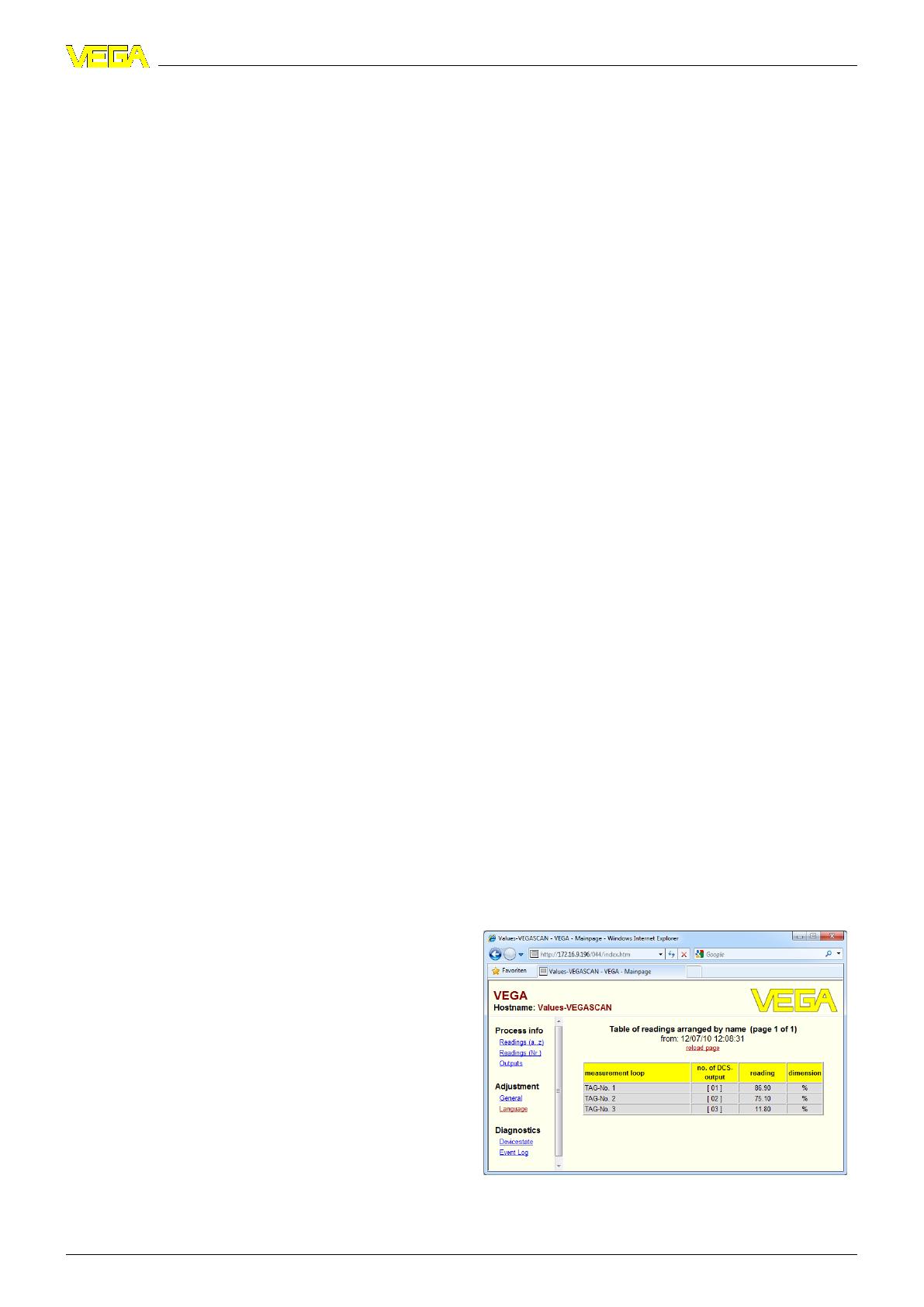
Web browser
The integrated web server can make the measured values available to
any individual user in the company network. The data is presented as an
HTML chart in a standard browser (e.g. Internet Explorer).
Instrumen
t selection
6 Signal
conditioning instruments and communications – Auswertgeräte für Grenzschalter
29251-EN-100805


