Page is loading ...

OPERATOR'S
MANUAL
Model 60/62
Shake Freezers
Original Operating Instructions
051059-M
4/00 (Original Publication)
Updated 9/26/16

Complete this page for quick reference when service is required:
Taylor Distributor:
Address:
Phone:
Service:
Parts:
Date of Installation:
Information found on the data label:
Model Number:
Serial Number:
Electrical Specs: Voltage Cycle
Phase
Maximum Fuse Size: A
Minimum Wire Ampacity: A
E 2000 Taylor Company
051059−M
Any unauthorized reproduction, disclosure, or distribution of copies by any person of any portion of this work may be
a violation of Copyright Law of the United States of America and other countries, could result in the awarding of Statutory
Damages of up to $250,000 (17 USC 504) for infringement, and may result in further civil and criminal penalties. All
rights reserved.
Taylor Company
750 N. Blackhawk Blvd.
Rockton, IL 61072

Models 60 & 62 Table of Contents
Table of Contents
Section 1 To the Installer 1............................................
Installer Safety 1........................................................
Site Preparation 1.......................................................
Water Connections (Water Cooled Units Only) 2............................
Air Cooled Units 2.......................................................
Electrical Connections 2.................................................
Beater Rotation 3.......................................................
Refrigerant 3...........................................................
Section 2 To the Operator 4...........................................
Compressor Warranty Disclaimer 4.......................................
Section 3 Safety 5....................................................
Section 4 Operator Parts Identification 7...............................
Section 5 Important: To the Operator 11.................................
Control Switch 11........................................................
Dial Light 11.............................................................
Indicator Light (“Mix Low”) 11..............................................
Indicator Light (“Mix Out”) 11..............................................
Reset Mechanism 12.....................................................
Consistency Control* 12..................................................
Spinner Rinse Switch* 12.................................................
Auto Lift Switch (Model 60 Only)* 12........................................
Foot Pedal (Model 60 Only) 12............................................
Flavor Selector Switch* 12................................................
Section 6 Operating Procedures 13.....................................
Assembly 13............................................................
Sanitizing 18............................................................
Priming 19..............................................................
Syrup System 21.........................................................
Drawing Product 23......................................................

Table of Contents Models 60 & 62
Table of Contents − Page 2
Closing Procedures 24...................................................
Draining Product From The Freezing Cylinder 24............................
Rinsing 24..............................................................
Cleaning 25.............................................................
Disassembly 25..........................................................
Brush Cleaning 26.......................................................
Sanitizing Syrup System 26...............................................
Section 7 Important: Operator Checklist 29..............................
During Cleaning and Sanitizing: 29.........................................
Troubleshooting Bacterial Count: 29........................................
Regular Maintenance Checks: 29..........................................
Winter Storage 30........................................................
Section 8 Troubleshooting Guide 31....................................
Section 9 Parts Replacement Schedule 35...............................
Section 10 Limited Warranty on Equipment 36............................
Section 11 Limited Warranty on Parts 38.................................
Note: Continuing research results in steady improvements; therefore, information
in this manual is subject to change without notice.
Note: Only instructions originating from the factory or its authorized translation
representative(s) are considered to be the original set of instructions.
E 2000 Taylor Company (Original Publication)
(Updated September, 2016)
051059−M
Any unauthorized reproduction, disclosure, or distribution of copies by any person of any portion of this
work may be a violation of Copyright Law of the United States of America and other countries, could result
in the awarding of Statutory Damages of up to $250,000 (17 USC 504) for infringement, and may result
in further civil and criminal penalties. All rights reserved.
Taylor Company
750 N. Blackhawk Blvd.
Rockton, IL 61072

1
Models 60 & 62 To the Installer
131108
Section 1 To the Installer
The following information has been included in the
manual as safety and regulatory guidelines. For
complete installation instructions, please see the
Installation Checklist.
Installer Safety
In all areas of the world, equipment should be
installed in accordance with existing local codes.
Please contact your local authorities if you have any
questions.
Care should be taken to ensure that all basic safety
practices are followed during the installation and
servicing activities related to the installation and
service of Taylor equipment.
S Only authorized Taylor service personnel
should perform installation and repairs on
the equipment.
S Authorized service personnel should consult
OSHA Standard 29CFRI910.147 or the
applicable code of the local area for the
industry standards on lockout/tagout
procedures before beginning any installation
or repairs.
S Authorized service personnel must ensure
that the proper PPE is available and worn
when required during installation and
service.
S Authorized service personnel must remove
all metal jewelry, rings, and watches before
working on electrical equipment.
The main power supply(s) to the machine
must be disconnected prior to performing any repairs.
Failure to follow this instruction may result in personal
injury or death from electrical shock or hazardous
moving parts as well as poor performance or damage
to the equipment.
Note: All repairs must be performed by an
authorized Taylor Service Technician.
This unit has many sharp edges that can
cause severe injuries.
Site Preparation
Review the area where the unit will be installed before
uncrating the unit. Make sure that all possible hazards
to the user and the equipment have been addressed.
For Indoor Use Only: This unit is designed to operate
indoors, under normal ambient temperatures of
70_-75_F (21_-24_C). The freezer has successfully
performed in high ambient temperatures of
104_(40_C) at reduced capacities.
This unit must NOT be installed in an area
where a water jet or hose can be used. NEVER use a
water jet or hose to rinse or clean the unit. Failure to
follow this instruction may result in electrocution.
This unit must be installed on a level surface
to avoid the hazard of tipping. Extreme care should be
taken in moving this equipment for any reason. Two or
more people are required to safely move this unit.
Failure to comply may result in personal injury or
equipment damage.
Uncrate the unit and inspect it for damage. Report any
damage to your Taylor Distributor.
This piece of equipment is made in the USA and has
USA sizes of hardware. All metric conversions are
approximate and vary in size.

2
Models 60 & 62To the Installer
110620
Water Connections
(Water Cooled Units Only)
An adequate cold water supply must be provided with
a hand shut−off valve. On the underside rear of the
base pan, two 3/8” I.P.S. water connections for inlet
and outlet have been provided for easy hook−up. 1/2”
inside diameter water lines should be connected to the
machine. (Flexible lines are recommended, if local
codes permit.) Depending on local water conditions, it
may be advisable to install a water strainer to prevent
foreign substances from clogging the automatic water
valve. There will be only one water “in” and one water
“out” connection. DO NOT install a hand shut−off valve
on the water “out” line! Water should always flow in this
order: first, through the automatic water valve; second,
through the condenser; and third, through the outlet
fitting to an open trap drain.
A back flow prevention device is required
on the incoming water connection side. Please
refer to the applicable National, State, and local codes
for determining the proper configuration.
Air Cooled Units
DO NOT obstruct air intake and discharge openings:
Air cooled units require adequate clearance around
the sides of the freezer to allow for adequate air flow
across the condenser.
Counter Models: 6” (152 mm) minimum air space on
both sides. It is recommended to place the rear of the
unit against the wall to prevent recirculation of warm
air.
Console Models: 3” (76 mm) minimum air space on
each side and rear of unit when air deflector is
employed.
Failure to allow adequate clearance can reduce the
refrigeration capacity of the freezer and possibly
cause permanent damage to the compressor.
Electrical Connections
Each unit requires one power supply for each data
label on the unit. Check the data label(s) on the freezer
for branch circuit overcurrent protection or fuse, circuit
ampacity, and other electrical specifications. Refer to
the wiring diagram provided inside the control box for
proper power connections.
In the United States, this equipment is intended to be
installed in accordance with the National Electrical
Code (NEC), ANSI/NFPA 70−1987. The purpose of
the NEC code is the practical safeguarding of persons
and property from hazards arising from the use of
electricity. This code contains provisions considered
necessary for safety. Compliance therewith and
proper maintenance will result in an installation
essentially free from hazard!
In all other areas of the world, equipment should be
installed in accordance with the existing local codes.
Please contact your local authorities.
FOLLOW YOUR LOCAL ELECTRICAL CODES!
CAUTION: THIS EQUIPMENT MUST BE
PROPERLY GROUNDED! FAILURE TO DO SO
CAN RESULT IN SEVERE PERSONAL INJURY
FROM ELECTRICAL SHOCK!
This unit is provided with an equipotential
grounding lug that is to be properly attached to the rear
of the frame by the authorized installer. The installation
location is marked by the equipotential bonding
symbol (5021 of IEC 60417-1) on both the removable
panel and the equipment’s frame.

3
Models 60 & 62 To the Installer
131105
S Stationary appliances which are not
equipped with a power cord and a plug or
another device to disconnect the appliance
from the power source must have an all-pole
disconnecting device with a contact gap of
at least 3 mm installed in the external
installation.
S Appliances that are permanently connected
to fixed wiring and for which leakage
currents may exceed 10 mA, particularly
when disconnected, not used for long
periods, or during initial installation, shall
have protective devices such as a GFI to
protect against the leakage of current and
be installed by authorized personnel to the
local codes.
S Supply cords used with this unit shall be
oil-resistant, sheathed, flexible cable, not
lighter than ordinary polychloroprene or
other equivalent synthetic
elastomer-sheathed cord (Code designation
60245 IEC 57) installed with the proper cord
anchorage to relieve conductors from strain,
including twisting, at the terminals and
protect the insulation of the conductors from
abrasion.
If the supply cord is damaged, it must be
replaced by the manufacturer, its service
agent, or similarly qualified person, in order
to avoid a hazard.
Beater Rotation
Beater rotation must be clockwise as viewed
looking into the freezing cylinder.
Note: The following procedures must be
performed by an authorized Taylor service
technician.
To correct the rotation on a three−phase unit,
interchange any two incoming power supply lines at
freezer main terminal block only.
To correct rotation on a single−phase unit, change the
leads inside the beater motor. (Follow the diagram
printed on the motor.)
Electrical connections are made directly to the
terminal block provided in the main control box.
Refrigerant
In consideration of our environment, Taylor
proudly uses only earth friendly HFC refrigerants. The
HFC refrigerant used in this unit is R404A. This
refrigerant is generally considered non-toxic and
non-flammable, with an Ozone Depleting Potential
(ODP) of zero (0).
However, any gas under pressure is potentially
hazardous and must be handled with caution. NEVER
fill any refrigerant cylinder completely with liquid.
Filling the cylinder to approximately 80% will allow for
normal expansion.
Use only R404A refrigerant that conforms to
the AHRI standard 700 specification. The use of any
other refrigerant may expose users and operators to
unexpected safety hazards.
Refrigerant liquid sprayed onto the skin may
cause serious damage to tissue. Keep eyes and skin
protected. If refrigerant burns should occur, flush
immediately with cold water. If burns are severe, apply
ice packs and contact a physician immediately.
Taylor reminds technicians to be cautious of
government laws regarding refrigerant recovery,
recycling, and reclaiming systems. If you have any
questions regarding these laws, please contact the
factory Service Department.
WARNING: R404A refrigerant used in
conjunction with polyolester oils is extremely moisture
absorbent. When opening a refrigeration system, the
maximum time the system is open must not exceed 15
minutes. Cap all open tubing to prevent humid air or
water from being absorbed by the oil.

4
Models 60 & 62To the Operator
131108
Section 2 To the Operator
The freezer you have purchased has been carefully
engineered and manufactured to give you dependable
operation. The Taylor Models 60 and 62, when
properly operated and cared for, will produce a
consistent quality product. Like all mechanical
products, these machines will require cleaning and
maintenance. A minimum amount of care and
attention is necessary if the operating procedures
outlined in this manual are followed closely.
This Operator’s Manual should be read before
operating or performing any maintenance on your
equipment. The Taylor Models 60 and 62 will NOT
eventually compensate and correct for any errors
during the set−up or filling operations. Thus, the initial
assembly and priming procedures are of extreme
importance. It is strongly recommended that
personnel responsible for the equipment’s operation,
both assembly and disassembly, sit down together and
go through these procedures in order to be properly
trained and to make sure that no misunderstandings
exist.
In the event you should require technical assistance,
please contact your local authorized Taylor Distributor.
Your Taylor warranty is valid only if the parts are
authorized Taylor parts, purchased from the local
authorized Taylor Distributor, and only if all required
service work is provided by an authorized Taylor
service technician. Taylor reserves the right to deny
warranty claims on units or parts if non−Taylor
approved parts or incorrect refrigerant were installed
in the unit, system modifications were performed
beyond factory recommendations, or it is determined
that the failure was caused by abuse, misuse, neglect,
or failure to follow all operating instructions. For full
details of your Taylor Warranty, please see the Limited
Warranty section in this manual.
If the crossed out wheeled bin symbol is
affixed to this product, it signifies that this product is
compliant with the EU Directive as well as other similar
legislation in effect after August 13, 2005. Therefore,
it must be collected separately after its use is
completed, and cannot be disposed as unsorted
municipal waste.
The user is responsible for returning the product to the
appropriate collection facility, as specified by your local
code.
For additional information regarding applicable local
laws, please contact the municipal facility and/or local
distributor.
Compressor Warranty Disclaimer
The refrigeration compressor(s) on this unit are
warranted for the term stated in the Limited Warranty
section in this manual. However, due to the Montreal
Protocol and the U.S. Clean Air Act Amendments of
1990, many new refrigerants are being tested and
developed, thus seeking their way into the service
industry. Some of these new refrigerants are being
advertised as drop−in replacements for numerous
applications. It should be noted that in the event of
ordinary service to this unit’s refrigeration system,
only the refrigerant specified on the affixed data
label should be used. The unauthorized use of
alternate refrigerants will void your Taylor compressor
warranty. It is the unit owner’s responsibility to make
this fact known to any technician he employs.
It should also be noted that Taylor does not warrant the
refrigerant used in its equipment. For example, if the
refrigerant is lost during the course of ordinary service
to this machine, Taylor has no obligation to either
supply or provide its replacement either at billable or
unbillable terms. Taylor does have the obligation to
recommend a suitable replacement if the original
refrigerant is banned, obsoleted, or no longer available
during the five year warranty of the compressor.
Taylor will continue to monitor the industry and test
new alternates as they are being developed. Should a
new alternate prove, through our testing, that it would
be accepted as a drop−in replacement, then the above
disclaimer would become null and void. To find out the
current status of an alternate refrigerant as it relates to
your compressor warranty, call the local Taylor
Distributor or the Taylor Factory. Be prepared to
provide the Model/Serial Number of the unit in
question.
Note: Constant research results in steady
improvements; therefore, information in this
manual is subject to change without notice.

5
Models 60 & 62 Safety
130507
Section 3 Safety
We, at Taylor Company, are concerned about the
safety of the operator when he or she comes in contact
with the freezer and its parts. Taylor has gone to
extreme efforts to design and manufacture built−in
safety features to protect both you and the service
technician.
IMPORTANT − Failure to adhere to the
following safety precautions may result in severe
personal injury. Failure to comply with these
warnings may damage the machine and its
components. Component damage will result in
part replacement expense and service repair
expense.
DO NOT operate the freezer without reading
this Operator Manual. Failure to follow this instruction
may result in equipment damage, poor freezer
performance, health hazards, or personal injury.
This appliance is to be used only by trained
personnel. It is not intended for use by children or
people with reduced physical, sensory, or mental
capabilities, or lack of experience and knowledge,
unless given supervision or instruction concerning the
use of the appliance by a person responsible for their
safety. Children should be supervised to ensure that
they do not play with the appliance.
This unit is provided with an equipotential
grounding lug that is to be properly attached to the rear
of the frame by the authorized installer. The installation
location is marked by the equipotential bonding
symbol (5021 of IEC 60417-1) on both the removable
panel and the equipment’s frame.
DO NOT use a water jet to clean or rinse the
freezer. Failure to follow these instructions may result
in serious electrical shock.
S DO NOT operate the freezer unless it is
properly grounded.
S DO NOT operate the freezer with larger
fuses than specified on freezer data label.
S All repairs must be performed by an
authorized Taylor service technician.
S The main power supplies to machine must
be disconnected prior to performing repairs.
S Cord Connected Units: Only Taylor
authorized service technicians may install a
plug on this unit.
S Stationary appliances which are not
equipped with a power cord and a plug or
another device to disconnect the appliance
from the power source must have an all-pole
disconnecting device with a contact gap of
at least 3 mm installed in the external
installation.
S Appliances that are permanently connected
to fixed wiring and for which leakage
currents may exceed 10 mA, particularly
when disconnected, not used for long
periods, or during initial installation, shall
have protective devices such as a GFI to
protect against the leakage of current and
be installed by authorized personnel to the
local codes.
S Supply cords used with this unit shall be
oil-resistant, sheathed, flexible cable, not
lighter than ordinary polychloroprene or
other equivalent synthetic
elastomer-sheathed cord (Code designation
60245 IEC 57) installed with the proper cord
anchorage to relieve conductors from strain,
including twisting, at the terminals and
protect the insulation of the conductors from
abrasion.
If the supply cord is damaged, it must be
replaced by the manufacturer, its service
agent, or similarly qualified person, in order
to avoid a hazard.
Failure to follow these instructions may result in
electrocution. Contact your local authorized Taylor
Distributor for service.

6
Models 60 & 62Safety
130507
S DO NOT allow untrained personnel to
operate this machine.
S DO NOT operate the freezer unless all
service panels and access doors are
restrained with screws.
S DO NOT remove any internal operating
parts (examples: freezer door, beater,
scraper blades, etc.) unless all control
switches are in the OFF position.
Failure to follow these instructions may result in severe
personal injury to fingers or hands from hazardous
moving parts.
This unit has many sharp edges that can
cause severe injuries.
S DO NOT put objects or fingers in the door
spout. This may contaminate the product
and cause severe personal injury from blade
contact.
S USE EXTREME CAUTION when removing
the beater asssembly. The scraper blades
are very sharp.
Access to the service area of the unit is
restricted to persons having knowledge and practical
experience with the appliance, in particular as far as
safety and hygiene are concerned.
This freezer must be placed on a level
surface. Failure to comply may result in personal injury
or equipment damage.
Cleaning and sanitizing schedules are
governed by your state or local regulatory agencies
and must be followed accordingly. Please refer to the
cleaning section of this manual for the proper
procedure to clean this unit.
This machine is designed to maintain product
temperature under 41_F (5_C). Any product being
added to this machine must be below 41_F (5_C).
Failure to follow this instruction may result in health
hazards and poor freezer performance.
DO NOT obstruct air intake and discharge openings:
Counter Models: 6” (152 mm) minimum air space on
both sides. Place the rear of the unit against the wall
to prevent recirculation of warm air.
Console Models: 3” (76 mm) minimum air space on
each side and rear of unit when air deflector is
employed.
Failure to allow adequate clearance can reduce the
refrigeration capacity of the freezer and possibly
cause permanent damage to the compressor.
For Indoor Use Only: This unit is designed to operate
indoors, under normal ambient temperatures of
70_-75_F (21_-24_C). The freezer has successfully
performed in high ambient temperatures of
104_(40_C) at reduced capacities.
DO NOT run the machine without product. Failure to
follow this instruction can result in damage to the
machine.
NOISE LEVEL: Airborne noise emission does not
exceed 78 dB(A) when measured at a distance of 1.0
meter from the surface of the machine and at a height
of 1.6 meters from the floor.

7
Models 60 & 62 Operator Parts Identi fication
160926
Section 4 Operator Parts Identification
Item Description Part No.
1 Cover A.- Hopper- Std. X38458 - SER
1a Knob- Mix Cover 025429
2 Tube- Feed- 1/4 Hole 015176- 5
3 Pan- Drip 19- 1/2 Long 035034
4 Shield- Splash- Wire 13- 11/16 L 046177
5 Tray- Drip 14.8 046275
6 Panel- Rear w/Louvers 026980- SP
7 Caster- 4” Swv 5/8 Stem w/Brake 034081
8 Panel - Side 067722
Item Description Part No.
9 Panel - Side 067721
10 Stud- Nose Cone 5/16 - 18 011390
11 Adaptor A.- Caster X18915
12 Panel A.- Front X46634
13 Pedal A.- Foot X48826
14 Caster- Swv 5/8 Stem 4” Wheel 018794
15 Screw- 1/4 - 20 x 3/8 Rhm- Stnls 011694
16 Tank - SYR- 4 QT 045533

8
Models 60 & 62Operator Parts Identification
160926
Model 62
Item Description Part No.
1 Cover A.−Hopper−Std. X38458−SER
1a Knob−Mix Cover 025429
2 Feed Tube 015176−5
3 Pan−Drip 19−1/2 Long 035034
4 Shield−Splash 022765
5 Tray−Drip 16−7/8 L x 5−1/8 020157
6 Panel−Rear 039021
7 Leg−4” SS w/O−ring 013458
Item Description Part No.
8 Panel−Side−Right 085411
9 Panel A.−Side Left X85409
10 Stud−Nose Cone 5/16−18 x
3/8−1
011390
11 Skirt−Air Flow 049069
12 Panel A.−Front X49996−1
13 Leg−4” SS w/O−ring 013458

9
Models 60 & 62 Operator Parts Identification
160926
Beater Assembly
ITEM DESCRIPTION PART NO.
1 SEAL−DRIVE SHAFT 032560
2 SHAFT−BEATER 035527
3 BEATER A.−7QT−1 PIN X46233
4 BEARING−FRONT 013116
5 GASKET−DOOR 016672
6 BEARING−GUIDE 014496
7 TORQUE A. X17381
8 ARM−TORQUE 014500
9 O−RING−.291 ID X .080W 018550
10 BEARING−SPINNER 017032
11 VALVE A.−DRAW X46671
12 O−RING−1−1/16 OD X.139W 084545
13 NUT−STUD 021508
*14 TUBE−VINYL 3/16ID X 1/16
WALL (MODEL 60)
020940−6
15 FITTING−QD MALE INSERT
(MODEL 60)
036296
ITEM DESCRIPTION PART NO.
16 O−RING−5/16 OD X .070W
(MODEL 60)
016272
17 DOOR A.−PARTIAL−1 SPT X17373−SER
18 HOUSING−SPINNER *4 SPIG 017269
19 BLADE−SCRAPER−PLASTIC 081094
20 BLADE A.−SPINNER (USED IN
006227CANH, 006233CANH,
006027CANH, 006033CANH,
0H6027CWMK &
0H6033CWMK ONLY)
X16961
21 BLADE A.−SPINNER 8−3/8”
(NOT USED IN 006227CANH,
006233CANH, 006027CANH,
006033CANH, 0H6027CWMK&
0H6033CWMK)
X35570
**22 FITTING−QD FEMALE PANEL
MOUNT (MODEL 60)
036295
ITEMS 14, 15, 16, & 21 USED ON MODEL 60 ONLY
*BULK PART NUMBER IS R30314
**NOT SHOWN

10
Models 60 & 62Operator Parts Identification
Syrup Tank
Item Description Part No.
1 Tank−Syr−4 Qt. 045533
1a Cover−Tank 8 Qt. w/Inlet Ftg. 035759−1
1b Tip−Nylon−White Translucent 042747
1c O−Ring−3.437 ID x .275 W 016037
1d Tube−Dip−4 Qt. Syr. Tank 015441−7
1d1 O−Ring−.291 ID x .080 W 018550
2 Plug−Q.D. CO2 1/8 MP 021077
3
Socket−Q.D. CO2 90_ 1/4 Barb
021524
4
Socket−Q.D. Liq.− 90_ 1/4 Barb
021026
Item Description Part No.
*4a Restrictor−Syrup 025816
4b Gasket−Rubber 023551
5 O−Ring−5/8 OD x .103 W 016030
6 Plug−Q.D. Liq. 3/4−18 FP 021081
6a Valve A.−Q.D. Plug 021081−2
6b Insert 021081−1
7 Decal−Set 4 Syrup Flavor 021523
8 Decal−Syrup Tank Instruction 045533−1
*Not used on chocolate

11
Models 60 & 62 Important: To the Operator
Section 5 Important: To the Operator
To better communicate in the International arena, the
words on many of our operator switches and buttons
have symbols to indicate their functions. Your Taylor
equipment is designed with these International
symbols.
The following chart identifies the symbol definitions
used on the operator switches:
= The “ON/AUTO” button.
= The “OFF” button.
= The “MIX” button.
= The “WASH” button.
= The “MIX LOW” button.
= The “MIX OUT” button.
= The “FILL” button.
= The “RINSE” button.
Control Switch
The center position is “OFF”. The left position is
“WASH”, which activates the beater motor only. The
right position is “AUTO”. It activates the beater motor
and the refrigeration system. To activate the
refrigeration system, raise the draw arm momentarily.
Dial Light
A red dial light is located on the right side of the control
switch. When the control switch is in the “AUTO”
position, this light will come on, indicating that the
refrigeration system is operable.
Indicator Light (“Mix Low”)
The mix low indicator light is located on the front of the
machine directly above the flavor selector switch.
When the light flashes, it indicates that the mix hopper
has a low supply of mix and should be refilled as soon
as possible. If mix is not added, a starved freezing
cylinder will cause damage to the beater, blades, and
drive shaft.
Indicator Light (“Mix Out”)
A mix out indicating light is located on the front of the
machine directly above the control switch. When the
light is on, the machine will shut down to prevent a
starved freezing cylinder.

12
Models 60 & 62Important: To the Operator
Reset Mechanism
The reset protects the beater motor from an overload
condition. If an overload occurs, the reset mechanism
will trip. To properly reset the freezer, set the control
switch to “OFF”. Lift up the right upper side panel and
press the reset button firmly. Turn the control switch to
“WASH” and observe the freezer’s performance.
Return the control switch to the “AUTO” position to
resume normal operation.
If the reset mechanism should trip again, contact your
authorized Taylor Distributor to resolve the problem.
Figure 1
Consistency Control*
The viscosity (thickness) of the shake is controlled by
a sensing device called the consistency control. The
consistency control switch is located below the control
switch. To achieve a thicker shake, turn the knob
clockwise and counterclockwise to achieve a thinner
shake consistency.
Allow the refrigeration system to cycle on and off two
or three times before an accurate consistency can be
evaluated.
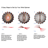
Spinner Rinse Switch*
The spinner rinse switch is located next to the
consistency control knob. To clean the spinner housing
from syrup residue:
1. Place the control switch in the “AUTO” position.
2. Hold a cup under the spinner housing.
3. Press the spinner rinse switch. Water will flow
until the switch is released.
4. Release the switch when the housing has been
thoroughly rinsed.
Auto Lift Switch (Model 60 Only)*
The auto lift switch is located below the flavor selector
switch. To draw product, the auto lift switch may be
used. Press the switch. Just before the desired level
in the cup is reached, release the switch. The draw arm
will lower the draw valve and the product will stop
flowing.
Foot Pedal (Model 60 Only)
The foot pedal is located on the lower front of the
machine. To draw product from the Model 60, the foot
pedal may be used. Press the foot pedal. Just before
the desired level in the cup is reached, release the foot
pedal. The draw arm will lower the draw valve and the
product will stop flowing.
Figure 2
Flavor Selector Switch*
The flavor selector switch consists of four flavor
buttons. The left button controls the No. 1 tank and its
lines. The second button from the left controls the No.
2 tank and its lines. The third button from the left
controls the No. 3 tank and its lines. The right selector
button (“Van”) is the “OFF” button and may be used to
dispense the unflavored product as a vanilla shake.
*See illustration, page 11.

13
Models 60 & 62 Operating Procedures
Section 6 Operating Procedures
The Models 60 and 62 have one, 7 quart (6.6 liter)
freezing cylinder. These totally automatic freezers
offer four separate flavors. Each flavor is blended and
ejected from the same spout. (Use only single strength
syrup that is free of pulp and seeds.)
We begin our instructions at the point where we enter
the store in the morning and find the parts
disassembled and laid out to air dry from the previous
night’s brush cleaning.
These opening procedures will show you how to
assemble these parts into the freezer, sanitize them,
and prime the freezer with fresh mix in preparation to
serve your first shake.
Figure 3
If you are disassembling the machine for the first time
or need information to get to this starting point in our
instructions, turn to page 25 “Disassembly”, and start
there.
Assembly
Note: When lubricating parts, use an approved food
grade lubricant (example: Taylor Lube).
MAKE SURE THE CONTROL SWITCH IS IN
THE “OFF” POSITION.
Step 1
Install the drive shaft. Lubricate the groove and shaft
portion that comes in contact with the bearing on the
beater drive shaft. Slide the seal over the shaft and the
groove until it snaps into place. DO NOT lubricate the
hex end of the drive shaft. Fill the inside portion of the
seal with 1/4” more lubricant. Lubricate the flat side of
the seal that comes in contact with the bearing.
Note: Make sure seal is not installed inside−out. The
ridge that protrudes in the center of the seal should be
on the outside.
Figure 4
Insert the drive shaft into the freezing cylinder, hex end
first, and into the rear shell bearing until the seal fits
securely over the rear shell bearing. Be certain the
drive shaft fits into the drive coupling without binding.
Figure 5

14
Models 60 & 62Operating Procedures
160926
Step 2
Before installing the beater assembly, inspect the
scraper blades.
Check the scraper blades for any signs of wear or
damage. If a scraper blade is nicked or worn, replace
both blades.
If the blades are in good condition, place the rear
scraper blade over the two rear holding pins (knife
edge to the outside).
Figure 6
Holding the rear blade on the beater, slide it halfway
into the freezing cylinder. Install the front scraper blade
over the front holding pins. Slide the beater assembly
the rest of the way into the freezing cylinder.
Figure 7
Make sure the beater assembly is in position over the
drive shaft. Turn the beater slightly to be certain that
the beater assembly is properly seated.
Figure 8
Step 3
Install the torque rotor assembly. Assemble the torque
rotor by sliding the two o−rings on the front of the shaft
and lubricate them thoroughly to prevent leaking.
Place the white plastic guide bearing on the rear of the
rotor shaft. DO NOT lubricate the plastic guide bearing
Figure 9

15
Models 60 & 62 Operating Procedures
150626
Insert the torque rotor, plastic guide bearing end first,
making sure that it fits into the hole in the beater drive
shaft. Rotate it several times to check for proper
positioning.
Figure 10
Step 4
Before assembling the freezer door, check the
following for any nicks, cracks, or signs of wear:
door bearing, door gasket, draw valve, o−rings, and all
sides of the door assembly, including the inside of the
draw valve bore. Replace any damaged parts.
Step 5
Install the draw valve. Lubricate the plastic spinner
bearing. Insert the plastic spinner bearing into the top
of the draw valve.
Figure 11
Slide the two o−rings onto the draw valve and lubricate
the draw valve.
Figure 12
Lubricate the inside of the door spout, top and bottom.
Insert the draw valve into the freezer door from the top.
It will be necessary to rotate the draw valve to the right
when assembling the door to the freezer.
Figure 13
Step 6
Place the large rubber gasket into the groove on the
back side of the freezer door. DO NOT lubricate the
gasket.
Figure 14

16
Models 60 & 62Operating Procedures
Slide the white plastic front bearing onto the bearing
hub, making certain that the flanged end of the bearing
sleeve is resting against the freezer door. DO NOT
lubricate the front bearing.
Figure 15
Install the door on the freezer by placing the torque
rotor shaft into the center hole of the freezer door.
Position the door on the four studs on the front of the
freezing cylinder.
Install the four handscrews onto the door and tighten
them equally in a criss−cross pattern.
Figure 16
Step 7
Install the drip pan. Slide the drip pan into the hole in
the front panel.
Figure 17
Step 8
Install the spinner housing. Snap the plastic spinner
housing onto the bottom of the door spout.
Figure 18
Lubricate the spinner blade shaft, and insert the
spinner blade from the bottom into the center of the
draw valve.
Figure 19
/