Page is loading ...

SPEECH JACK INSTALLATION GUIDE
PCI KEYPAD UPGRADE COMPLETED
(MODEL 96XX)
TDN 07103-08205-00
March 27, 2012
CORPORATE HEADQUARTERS:
21405 B S
TREET
LONG BEACH, MS 39560
P
HONE: (800) 259-6672
F
AX: (228) 868-9445
RMA (RETURN MATERIAL A UTHORIZATION)
RETURN ADDRESS:
21405 B S
TREET
LONG BEACH, MS 39560
© 2012 Triton. All Rights Reserved. TRITON logo is a
registered trademark of Triton Systems of Delaware, LLC

2
SPEECH INSTALLATION GUIDE
** Important **
The upgrade procedures may require removal and replacement of electrostatic
sensitive devices such as integrated circuits, boards, and assemblies. ESD
wrist straps should be worn and connected to a common ground point to
prevent hazardous electrostatic discharge to sensitive components. Failure
to follow proper handling or use of these items may result in damage from
ESD.
* NOTE *
This instruction is to be used for the installtion of the speech jack on 96xx
units that have had the PCI Keypad (oyster) kit upgrade completed. There
should be no software nor circuit board replacement requirement.
Updates:
April 4, 2011 original
September 28, 2011 picture edits
March 27, 2012 picture edits

3
SPEECH INSTALLATION GUIDE
This guide covers the steps for installing a speech (headphone jack) kit for
Model 96XX ATMs. This procedure includes a list of tools and hardware re-
quired for the upgrade as well as the steps involved.
SCOPE
INTRODUCTION
This procedure applies to all service personnel involved in the process of
maintaining or converting Triton ATMs.
REQUIRED PARTS AND TOOLS
* IMPORTANT *
The Speech upgrade for the 96XX ATM requires:
 SD04.01 EPROM or higher installed in the Memory Module (SS-2).
 The quad port multifunction board from the PCI upgrade installation
* 1 Mbyte or greater Memory Expansion module is optional.
* This item is NOT included in the kit. You may already have this installed.
DERIUQERSLOOT
)citengaM(revirdwercSspillihP2#)"61/7dna"8/1(stibllirddnallirD
revirDtuN)"61/7reluRroerus
aeMepaT
)licneP(rekraM
TIKNOITALLATSNIHCEEPSXX69
)50280-00260N/P(
DEILPPUSSTRAP
REBMUNTRAP NOITPIRCSED YTITNAUQ
01400-02190
lbaCenohpdaeH
e
1
55010-11030
ilCreniateRkcaJhceepS
p
1
20000-27020
senraHeriWdedurtxE,pilC
s
1
51070-02190
riWdnuorG
e
retpadA
1
90000-27030evisehdAtiudnaP,pilC2
01000-03010
etirreF1
10883-00070
lliarB,lebaL
e
1

4
SPEECH INSTALLATION GUIDE
Installation
Follow these steps to install the speech installation kit for the Model 96XX
ATM:
1. Unlock and open the control panel. Verify that the power switch is in the
OFF (0) position. Close the control panel.
2. Using a tape measure/ruler, mark a point 1- 1/2" from the bottom left edge
shown in Figure 1. From
that mark, measure 1-1/2” down and place another
mark (Figure 2).
This will be the drill point. Erase the previous mark. Figure
3 shows the drill point location.
Figure 3. Drill point location.
Figure 1. Measure 1-1/2" across.
Figure 2. Measure 1-1/2" down.
* Important *
When routing the headphone cables in the control panel, it is critical
that cables are isolated from the main ribbon cable that runs from the
card cage to the keypad. DO NOT ROUTE/SECURE HEADPHONE
CABLE WITH THIS RIBBON CABLE!

5
SPEECH INSTALLATION GUIDE
3. Drill a pilot hole using the 1/8” drill bit and finish using the 7/16" bit (Figures
4 and 5).
4. Open the control panel and feed the headphone cable (audio jack side first,
Figure 6) through the hole (exterior) until the headphone plug is flush in the
hole (Figure 7).
Figure 4. Drill pilot hole. Figure 5. Finish with 7/16" bit.
Figure 6. Feed cable in hole. Figure 7. Headphone plug flush.
5. (Inside control panel) Secure the headphone plug with the retainer clip
shown in Figure 8. Insert the retainer clip approximately half way.
Figure 8. Insert retainer clip to secure.

6
SPEECH INSTALLATION GUIDE
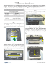
6. Using a 7/16" nutdriver, remove the bolt shown in Figure 9. Install the ground
wire adapter and secure with bolt previously removed (Figure 10). Connect
the ground wire from the headphone cable to this adapter.
Figure 9. Remove bolt.
Figure 10. Install ground wire adapter.
7. Install an extruded wire harness clip to the speaker screw shown in Figure 11.
Route the cable under and through the clip so cable has a “bow”. Next,
install the adhesive-backed clip between the 2 center-pin torx screws (figure
12). Figure 13 shows the headphone cable routing.
Figure 11. Install clip and
route cable.
Figure 12. Install flat clip and
secure cable.
Figure 13. Cable routing.
Cable routing

7
SPEECH INSTALLATION GUIDE
9. Omitted
8. Pull the Memory module from the card cage (SS-2) and verify the EPROM
version is 04.01 or higher (Figure 14). If not, install the required upgraded
EPROM (included in kit) following ESD precautions and correct orientation
of the chip. Reinstall the memory module after completion.
Figure 14. Memory module
EPROM location.

8
SPEECH INSTALLATION GUIDE
10. Open the ferrite included in kit. Wrap the headphone cable in the ferrite as
shown in Figure 17. Position the ferrite as close as possible to the headphone
jack and snap ferrite together. Plug the headphone jack into the jack provided
on the Tri-Port/Speech module shown in Figure 18.
11. Secure any excess cable to the cable
clip shown in Figure 19.
Figure 17. Install cable in ferrite.
Figure 18. Connect cable to
Multi function board.
Figure 19. Secure excess cable.
12. Affix the Braille label approximately
1/4" to the right of the headphone
plug as shown in Figure 20. Ensure
correct orientation of label .
Figure 20. Affix Braille label.
/