Page is loading ...

DC
OUT
RECALL
•
MODE
ACTIVATE
•
LOCK
SET
RUN
▲
▼
LOG
▲
▼
L
O
G
R
C
L
S
E
T
°C
°F
H
I
( )
L
O
( )
T
amb
L
A
S
E
R
Rev H
6/98
56700-1
RAYNGER
®
3i
™
SERIES
OPERATOR’S MANUAL


WARRANTY
Raytek warrants each instrument it manufactures to be free from defects in material and work-
manship under normal use and service for the period of one year from date of purchase. This
warranty extends only to the original purchaser. This warranty shall not apply to fuses, batteries,
or any product which has been subject to misuse, neglect, accident, or abnormal conditions of
operation.
In the event of failure of a product covered by this warranty, Raytek will repair the instrument
when it is returned to an authorized Service Facility within one year of the original purchase,
provided the warrantor’s examination discloses to its satisfaction that the product was defective.
The warrantor may, at its option, replace the product in lieu of repair. With regard to any instru-
ment returned within one year of the original purchase, said repairs or replacement will be made
without charge. If the failure has been caused by misuse, neglect, accident, or abnormal condi-
tions of operation, repairs will be billed at nominal cost. In such cases, an estimate will be sub-
mitted before work is started, if requested.
THE FOREGOING WARRANTY IS IN LIEU OF ALL OTHER WARRANTIES, EXPRESSED
OR IMPLIED, INCLUDING BUT NOT LIMITED TO ANY IMPLIED WARRANTY OF MER-
CHANTABILITY, FITNESS, OR ADEQUACY FOR ANY PARTICULAR PURPOSE OR USE.
RAYTEK SHALL NOT BE LIABLE FOR ANY SPECIAL, INCIDENTAL, OR CONSEQUEN-
TIAL DAMAGES, WHETHER IN CONTRACT, TORT, OR OTHERWISE.
WORLDWIDE HEADQUARTERS
Raytek Corporation
1201 Shaffer Road, PO Box 1820
Santa Cruz, CA 95061-1820 USA
Portable Products Division
800 866 5478
Phone 408 458 1110
Fax 408 425 4561
WORLD WIDE WEB
www.raytek.com
EUROPEAN HEADQUARTERS
Raytek GmbH
Arkonastrasse 45-49
D-13189 Berlin, Germany
Phone 49 30 478 0080
FAX 49 30 471 0251
Offices worldwide:
BRAZIL
Raytek do Brasil
Sorocaba, Brasil
Phone 55 152 276556
CHINA
Raytek China Company
Beijing, China
Phone 86 10 437 0284
JAPAN
Raytek Japan, Inc.
Tokyo, Japan
Phone 03 5976 1531
MEXICO
Raytek de Mexico
Puebla, Mexico
Phone 52 22 30 4380
UNITED KINGDOM
Raytek UK
Milton Keynes, UK
Phone 44 1 908 630800
® Raytek and Raynger are registered trademarks and 3i is a trademark of Raytek Corporation
© 1997 Copyright Raytek Corporation


Raynger 3i Series Operator's Manual Table of Contents
TABLE OF CONTENTS
SECTION PAGE
1.0 INTRODUCTION.............................................................................1-1
1.1 DESCRIPTION.......................................................................................................1-1
1.2 INVENTORY ..........................................................................................................1-2
1.3 MODEL IDENTIFICATION.................................................................................1-3
2.0 OPERATION......................................................................................2-1
2.1 QUICK START........................................................................................................2-2
2.2 PRINCIPLES OF OPERATION............................................................................2-3
2.3 YOUR PORTABLE INFRARED THERMOMETER...........................................2-4
2.4 OPERATION AND CONTROLS.........................................................................2-6
2.4.1 Battery/AC Adaptor Installation...................................................................2-6
2.4.2 Control Panel and Display..............................................................................2-7
2.4.3 Control System ...............................................................................................2-10
2.4.3.1 Control Loops..............................................................................................2-10
2.4.3.2 General Information....................................................................................2-11
2.4.4 RUN Loop—To Measure Temperature.......................................................2-12
2.4.5 LOG Loop—To Measure and Store Temperature......................................2-14
2.4.6 RECALL Loop—To Recall Measured Temperature ..................................2-16
2.4.6.1 RECALL Values from RUN .......................................................................2-16
2.4.6.2 RECALL Values from LOG........................................................................2-17
2.4.7 SETUP Loop—To Setup and Activate Alarms and Features...................2-19
2.4.7.1 SETUP Values for RUN ..............................................................................2-19
2.4.7.2 SETUP Values for LOG...............................................................................2-21
2.5 USING A TRIPOD...............................................................................................2-22
2.6 DATA OUTPUTS .................................................................................................2-23
2.6.1 Digital Output.................................................................................................2-24
2.6.1.1 Data Output—RUN Loop..........................................................................2-24
2.6.1.2 Data Output—SET Loop............................................................................2-25
2.6.1.3 Data Output—LOG Run Loop..................................................................2-26
2.6.1.4 Data Output—LOG SETUP Loop.............................................................2-27
2.6.2 Analog Output................................................................................................2-28
SECTION PAGE

Table of Contents Raynger 3i Series Operator's Manual
2.7 SIGHTING SYSTEMS..........................................................................................2-29
2.7.1 Single Laser Sighting .....................................................................................2-31
2.7.2 Dual Laser Sighting........................................................................................2-31
2.7.3 Crossed Laser Sighting..................................................................................2-32
2.7.4 Scope Sighting ................................................................................................2-32
3.0 SPECIFICATIONS ............................................................................3-1
3.1 THERMAL..............................................................................................................3-1
3.2 OPERATIONAL.....................................................................................................3-2
3.3 ELECTRICAL .........................................................................................................3-3
3.4 ENVIRONMENTAL..............................................................................................3-4
3.5 PHYSICAL..............................................................................................................3-4
3.6 DEFAULT VALUES ...............................................................................................3-5
3.7 REGULATORY.......................................................................................................3-6
4.0 MAINTENANCE...............................................................................4-1
4.1 BATTERY REPLACEMENT.................................................................................4-1
4.2 CLEANING ............................................................................................................4-1
4.2.1 Front Window Cleaning..................................................................................4-1
4.2.2 Cleaning the Housing......................................................................................4-2
4.3 LASER MAINTENANCE.....................................................................................4-2
SECTION PAGE

Raynger 3i Series Operator's Manual Table of Contents
APPENDIX A: OPTICAL...........................................................................A-1
HOW TO READ THE OPTICAL CHARTS...................................................................A-1
OPTICAL CHARTS ..........................................................................................................A-2
APPENDIX B: OBJECT EMISSIVITY.......................................................B-1
HOW TO DETERMINE OBJECT EMISSIVITY.............................................................B-1
TYPICAL EMISSIVITY VALUES.....................................................................................B-2
APPENDIX C: TROUBLESHOOTING ....................................................C-1
APPENDIX D: OPTIONS AND ACCESSORIES...................................
D-1
APPENDIX E: TRACEABILITY OF
INSTRUMENT CALIBRATION...............................................................E-1
APPENDIX F: CE CONFORMITY FOR THE
EUROPEAN COMMUNITY......................................................................F-1
GLOSSARY OF TERMS
INDEX

Table of Contents Raynger 3i Series Operator's Manual

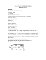
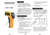
Raynger 3i Series Operator’s Manual 1-1
1.0 INTRODUCTION
1.1 DESCRIPTION
The Raynger
®
3i
™
series of instruments are portable infrared temperature measure-
ment devices. Each model is rugged and easy to use for making fast, noncontact, non-
destructive temperature measurements. They can measure operating temperatures of
mechanical, electrical, or production equipment without removing the equipment
from service. They can also measure product temperatures during manufacturing or
storage without contaminating or marring the product. Table 1-1 lists the standard
Raynger 3i models.
Table 1-1: Raynger 3i Models
TEMPERATURE OPTICAL SPECTRAL
MODEL RANGE RESOLUTION RANGE SIGHTING
LTDL2 &
LTDL3
LTSC
LTCL2 &
LTCL3
LRSC
LRSCL2
LRL2 &
LRL3
P7DL2 &
P7DL3
G5SC
1MSC
1ML2 &
1ML3
2MSC
2ML2 &
2ML3
-30 to 1200°C
(-20 to 2200°F)
-30 to 1200°C
(-20 to 2200°F)
-30 to 1200°C
(-20 to 2200°F)
-30 to 1200°C
(-20 to 2200°F)
-30 to 1200°C
(-20 to 2200°F)
-30 to 1200°C
(-20 to 2200°F)
10 to 800°C
(50 to 1450°F)
150 to 1800°C
(300 to 3275°F)
600 to 3000°C
(1100 to 5400°F)
600 to 3000°C
(1100 to 5400°F)
200 to 1800°C
(400 to 3275°F)
200 to 1800°C
(400 to 3275°F)
75:1
75:1
75:1
120:1
105:1
120:1
25:1
50:1
180:1
180:1
90:1
90:1
8-14 µ
8-14 µ
8-14 µ
8-14 µ
8-14 µ
8-14 µ
7.9 µ
5.0 µ
1.0 µ
1.0 µ
1.6 µ
1.6 µ
dual laser
scope
crossed laser
scope
single laser with scope
single laser
dual laser
scope
scope
single laser
scope
single laser

1-2 Raynger 3i Series Operator’s Manual
Each model is molded from rugged, high-strength, solvent resistant plastic and is
actuated by a two-stage trigger (second stage is used for data logging only). Each
model has the following:
• High quality optical system
• Infrared detector
• Circuit board assembly with microprocessor
• LCD display with backlighting feature
• Touch-sensitive membrane switches for changing loops and modes
• Battery compartment for four AA batteries
• Power input jack for AC adaptor
• Signal output jack (analog 1mV per degree/digital RS232)
• A rugged, padded pouch for easy carrying
There are four types of laser sighting models:
• Single laser—shows the center of the measurement area.
• Dual laser—shows the spot diameter of the measurement area.
• Crossed laser—the point where the two laser beams cross is the location of the
minimum diameter measurement spot.
• Single laser with scope
1.2 INVENTORY
Your Raynger 3i package contains the following:
• Raynger 3i
• Carrying Case
• Operator’s Manual
• Four (4) AA batteries
• Warranty card

Raynger 3i Series Operator’s Manual 1-3
1.3 MODEL IDENTIFICATION
Refer to Table 1-1 for a list of standard models along with their temperature ranges,
optical resolutions, spectral ranges, and sighting systems.
You can determine the exact model number of your unit by looking at the manufac-
turing label on the underside of the unit. On the label is an area for model designa-
tion. The model type is printed in the following format:
XXXYYYZZZZZ
where XXX is an abbreviation of the company name, YYY is the product (or abbrevia-
tion of the product name), and ZZZZZ is the model type. (Model type may be four or
five characters long. Refer to Table 1-1 to compare the label to model type.)

1-4 Raynger 3i Series Operator’s Manual

Raynger 3i Series Operator’s Manual 2-1
2.0 OPERATION
This portion of the manual contains the following sections:
• Quick Start—To use your unit right away, follow the brief instructions on basic
operating procedures in this section.
• Principles of Operation—A short introduction to infrared thermometry.
• Your Portable Infrared Thermometer—Describes and illustrates the thermome-
ter’s control panel, display, and features.
• How to Operate—A detailed user guide that describes each of the operating
modes. It includes descriptions of the RUN, RECALL, SETUP, and Data Logger
loops.
• Data Outputs—How to use the analog and digital (RS232) outputs to connect the
thermometer to a printer, chart recorder, or computer.
WARNING—LASER SAFETY
Models with laser sighting produce visible laser radiation that may be
harmful to the human eye. Be aware of the following:
• Avoid direct exposure of human eyes to laser light. Eye damage
can result.
• Use extreme caution when operating.
• Never point the unit at another person.
• Keep out of the reach of children.
• Refer to the FDA laser label on the unit for specific information.
IMPORTANT
1. If the unit is exposed to significant changes in ambient temperature
(hot to cold or cold to hot), allow 45 minutes for temperature stabi-
lization before taking measurements.
2. Do not operate the unit near large electrical or magnetic fields such
as arc welders and induction heaters. These fields can cause mea-
surement errors.
3. For the short wavelength units (e.g., 2 µm and below)—Avoid taking
temperature measurements in bright sunlight. High levels of ambi-
ent light may produce apparently valid high-temperature readings
when no target is in the thermometer’s field-of-view.

2-2 Raynger 3i Series Operator’s Manual
RUN
LOG
SET
LOG
RCL
SET
°C °F
HI
( )
LO
( )
T
amb

Raynger 3i Series Operator’s Manual 2-3
2.2 PRINCIPLES OF OPERATION
An infrared thermometer and the human eye are very similar. An infrared ther-
mometer has a lens that focuses infrared radiation from an object onto a detector. The
eye focuses light onto the retina. The detector is stimulated by the incoming infrared
energy and produces a signal that is transmitted to the circuitry. The retina is stimu-
lated by incoming light and sends a signal to the brain. The circuitry processes this
signal and computes the temperature of the object.
The intensity of an object’s emitted infrared energy increases or decreases in propor-
tion to its temperature. The higher the temperature of the target, the greater the inten-
sity of infrared radiation.
To calibrate a noncontact temperature measurement instrument, the manufacturer
uses a blackbody. A blackbody is a perfect emitter because it absorbs and emits all
radiant energy but reflects or transmits none. The emissivity value of a blackbody is
1.00. Figure 2-2 shows the radiant emittance values of a blackbody at various tem-
peratures and wavelengths.
Most objects have emissivities that are less than 1.00 but are reasonably uniform at all
wavelengths of the infrared spectrum. These are called graybodies. The non-ideal
(less then 1.00) emissivity values of different materials can be compensated for, by the
emissivity controls, so that accurate temperature readings can be obtained. Emissivity
values for many common materials (both metals and non-metals) are listed in
Appendix B.
0
123
4
56
7
8
9 10111213
14
10
10
10
10
1
10
10
2
1
-1
-2
-3
-4
Wavelength (Microns)
Blackbody Radiant Emittance (Watt/cm )
2
1500°C (2730°F)
1000°C (1830°F)
542°C (1000°F)
260°C (490°F)
20°C (70°F)
Figure 2-2: Blackbody Radiation Curves

2-4 Raynger 3i Series Operator’s Manual
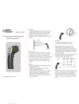
2.3 YOUR PORTABLE INFRARED THERMOMETER
Portable infrared thermometers measure surface temperatures without touching the
surface. They collect the infrared energy radiated by a target and compute its surface
temperature. They also compute the running average, maximum, minimum, and dif-
ferential temperatures and present them on a digital display in either degrees Celsius
or Fahrenheit. A digital/analog output allows data recording, instrumentation or
process control, and/or remote display of temperature and emissivity. The instru-6(. The instr)7.6contr is batmety powerared/ocan be powerared byionptatiitaAC adaprato7354.6(. he)]TJ0 -2.4158 Tg0 TwInmetiitamemoty cirart aum, anacs danalgnninfea-he

Raynger 3i Series Operator’s Manual 2-5
Your portable thermometer has the following:
• Trigger—Two-stage trigger. The first stage activates the unit to take temperature
readings. The second stage is functional only in the datalog mode. To store a tem-
perature reading, pull the trigger all the way in until you hear the tone (the tone
signals that the reading has been stored). When you release the trigger, the unit
goes to sleep.
• Control Panel and Display—All controls (except the trigger) are located on the
control panel. The display shows temperature and setup values, mode and loop
status, and operating information.
• Sighting System—Laser or scope sighting is provided with each model.
Note: Read the laser warning label before operating the laser.
• Analog Output—Connects the instrument to analog recording/printing devices
such as chart recorders and printers.
• Digital Output—An RS232 interface to connect the instrument to a computer or
directly to a printer’s RS232 port.
• DC In—AC adaptor connection.

2-6 Raynger 3i Series Operator’s Manual
2.4 OPERATION AND CONTROLS
This section instructs you in the operation of the instrument. It describes battery
and/or AC adaptor installation and the controls and functions of the different control
loops and operating modes.
2.4.1 Battery/AC Adaptor Installation
The instrument may be powered by batteries or an AC adaptor. Battery power is sup-
plied by 4 “AA” batteries. The batteries are located in the base of the handle. AC
power is supplied by an optional AC power adaptor (DIN VDE 0551 approved).
NiCad batteries can also be used, but battery life will be substantially reduced. Figure
2-3 shows the location of the battery compartment, battery orientation, and the loca-
tion of the AC adaptor power connection.
Table 2-1 shows approximate battery life (for alkaline batteries) for various operating
conditions.
Notes: Battery types and brands vary in length of usable life. The values in Table 2-1 are
approximate for new alkaline batteries. The instrument will continue to read accurate-
ly up to 4 hours after the low battery icon displays if the laser and backlight are off.
Remove the batteries if the unit is not used for long periods of time.
220 VAC adaptors must have DIN VDE 0551 approval to be used with IEC Class 2
laser units.
Table 2-1: Battery Life (Alkaline)
CONDITION
HOURS OF
CONTINUOUS USE
Laser OFF Backlight OFF
Laser ON Backlight OFF
Laser OFF Backlight ON
Laser ON Backlight ON
"Sleep" mode (trigger off)
25
12.5
12.5
10
1 year

Raynger 3i Series Operator’s Manual 2-7
RUN
LOG
SET
MODE
•
RECALL
ACTIVATE
•
LOCK
LOG
RCL
SET
°C °F
HI
( )
LO
( )
T
amb
Celsius/Fahrenheit
icons
Temperature
display
High and low
alarm icons
Ambient temperature
compensation icon
Low battery icon
Emissivity display
Mode value display
Trigger lock
icon
Backlight
icon
Mode display
Laser on/off LED
Data logger
icon
Recall
loop icon
Setup
loop icon
RUN
LOG
RECALL
•
MODE
ACTIVATE
•
LOCK
LASER
Figure 2-4: The Control Panel and Display
2.4.2 Control Panel and Display
Figure 2-4 shows the display and controls. Descriptions of these, in alphabetical
order, follow the illustration.
RUN
LOG
SET
MODE
•
RECALL
ACTIVATE
•
LOCK
LOG
RCL
SET
°C °F
HI
( )
LO
( )
T
amb
Increase/up
button
Decrease/down
button
Activate and trigger
lock button
Backlight on/off
button
Run/Log
selector switch
Setup
button
Mode and Recall
button
Laser on/off button
RUN
LOG
RECALL
•
MODE
ACTIVATE
•
LOCK
LASER

2-8 Raynger 3i Series Operator’s Manual
Activate button—Press the activate button to activate HAL, LAL, or TAM, or to tog-
gle between DIG/ANA, or °C/°F, in the SET loop.
Backlight button and icon—The display has a backlight for working in low lighting
conditions. Press the backlight button to activate or deactivate the backlight. The
backlight icon is activated when the backlight is on. To save battery power, use the
backlight only when necessary. Note that if the battery voltage falls below 4.0 V, the
backlight will automatically turn off.
Low battery icon—The instrument is powered by four “AA” batteries. When the bat-
tery voltage falls below 4.6 V, the low battery icon is activated.
Note: Turning off the backlight and laser will extend the battery life (refer to Table 2-1 for
battery life under various conditions).
Celsius/Fahrenheit icons—The °C and °F icons indicate which temperature scale has
been selected.
LOG button and icon—Press the LOG/RUN button while you have the trigger
pulled to toggle between the LOG and RUN loops. The LOG icon is activated when
the instrument is in the LOG loop.
Emissivity display—The emissivity display shows the emissivity value selected in
either the RUN, RECALL, or LOG loops.
▲▲
and
▼▼
buttons—▲ increases and ▼ decreases the emissivity settings, DOI rate,
HAL or LAL set-points, TAM, or the LOG location number.
High and Low alarm icons—These are activated when the corresponding alarms are
activated. The HAL icon flashes and the buzzer sounds when measured temperature
is greater than or equal to HAL and HAL is active. The LAL icon flashes and the
buzzer sounds when the measured temperature is less than or equal to LAL and LAL
is active. Note that when a high or low alarm condition is met and the unit is sending
out RS232 data while in the Digital Output mode, the buzzer will make two tones: a
normal tone followed by a higher pitched tone.
Laser on/off button and LED—Press the laser button to activate or deactivate the
laser (RUN and LOG loops only). The laser LED is activated when the laser is activat-
ed. (Not applicable for the scope sighting model.) Note that if the battery voltage
falls below 4.3 V, the laser will automatically turn off. Also, if the unit is in the LOCK
mode, the laser will go off when the trigger is released.
Temperature display—Shows the current temperature (while the trigger is pulled) or
the last temperature measured (when the RECALL button is pressed).
/