Page is loading ...

Specifications
Air Inlet ....................................................
1
⁄4" NPT
Average Air Consumption ........................ 4 CFM
Operating Pressure ........................... 30-100 PSI
Capacity ................... 14 oz., (400cc bulk grease)
Weight ........................................3.5 lbs. (Empty)
Inventory (Figure 1) Qty
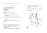
A. Grease Gun ............................................... 1
B. Hydraulic Coupler with Extension .............. 1
Operation
To improve tool lifespan, use a filter/lubricator/
regulator setup as shown in Figure 2
.
Otherwise, lubricate multiple times daily with 2–3
drops of pneumatic tool oil. Place the oil directly
into the air fitting as shown in Figure 3
.
Figure 1. Model H8223.
Figure 3. Lubricating directly into air fitting.
If you need help with your new pneumatic tool,
call our Tech Support at: (570) 546-9663.
COPYRIGHT © AUGUST, 2007 BY GRIZZLY INDUSTRIAL, INC.
WARNING: NO PORTION OF THIS MANUAL MAY BE REPRODUCED IN ANY SHAPE
OR FORM WITHOUT THE WRITTEN APPROVAL OF GRIZZLY INDUSTRIAL, INC.
#LOJM9800 PRINTED IN CHINA
EYE INJURY HAZARD!
Always wear safety glasses
during use to prevent
serious personal injury.
INJURY HAZARD!
When servicing, always dis
-
connect tool from air to pre
-
vent unexpected operation.
120 PSI
MAX AIR PRESSURE!
Exceeding this PSI may
result in injury/tool damage.
Quick
Connector
Quick
Coupler
Air Hose
Quick
Coupler
Quick
Connector
Lubricator
Filter
Regulator
Air
Compressor
Your
Tool
Figure 2. Installing a filter/lubricator/regulator to
improve the lifespan of your tool.
MODEL H8223
PNEUMATIC GREASE
GUN
INSTRUCTION SHEET
Grease Gun
Hydraulic Coupler Extension

-2-
H8223 Pneumatic Grease Gun
3. Remove the head assembly (Figure 1), from
the container body.
4. If an empty cartridge is in the gun, remove
it by carefully pushing the locking tab and
allowing the follower rod to slowly move into
the container body.
5. After ejecting the used cartridge, pull the
follower rod back until it is fully extended,
and allow the locking tab to hold it in place
(Figure 4).
6. Remove the caps from both ends of the new
grease cartridge and insert the cartridge into
the container body according to the instruc
-
tions on the cartridge body.
7. Securely fasten the head assembly to the
container body and release the follower rod
by pushing on the locking tab.
8. Push the follower rod in as far as possible.
To operate your H8223 grease gun:
1. Connect the grease gun to compressed air
regulated at a pressure between 30 and 100
PSI.
Note: For quick connection type air fittings,
a
1
/4" NPT female plug is needed (sold sepa-
rately.)
2. Wipe all fittings clean with a shop towel.
3. Pull grease gun trigger once or twice to
purge the coupler of any contaminates or old
grease.
4. Push the grease gun coupler onto the fitting
to be lubricated.
Note: It is easier to attach the coupler to the
fitting at a slight angle. Be sure to center
the coupler over the fitting when applying
grease.
5. Pull the trigger to inject grease.
6. After lubricating, turn the coupler at a slight
angle to release it from the fitting.
Installing a Grease Cartridge
To install a grease cartridge, the follower assem-
bly must be fully withdrawn, allowing room for the
new cartridge.
To properly load a new grease cartridge:
1. DISCONNECT THE TOOL FROM THE AIR
SUPPLY!
2. Pull the follower rod back until it is fully
extended; the locking tab will automatically
hold it in place (Figure 4
).
NOTICE
Some mechanical systems may only require
a small amount of grease, while others
require much more. Understand the lubri
-
cation requirements of the part you are
lubricating. Failure to follow this instruction
can damage seals or under-lubricate parts,
causing costly damage.
Figure 4. The follower rod and locking tab
Follower Rod
Locking Tab

-3-
H8223 Pneumatic Grease Gun
Filling With a Bulk Grease Pump
1. DISCONNECT THE TOOL FROM THE AIR
SUPPLY!
2. Insert the grease gun grease inlet seat (part
# 34) into the proper fitting on the pump oper
-
ated bulk grease container.
3. Operate the bulk grease pump to fill the
grease gun container.
Bleeding Air Pockets
If at any time you experience problems with the
grease gun dispensing grease, especially after
refilling, air is likely trapped in the head assem
-
bly.
To bleed air pockets from the grease gun:
1. DISCONNECT THE TOOL FROM THE AIR
SUPPLY!
2. Pull back on the follower rod until it is fully
extended (Figure 4
).
3. Release the follower rod by pushing on the
locking tab.
4. Push the follower rod all the way forward
while holding down the bleeder valve shown
in Figure 5.
5. Reconnect the grease gun to the air supply,
and pull the trigger several times to release
any air in the head assembly and verify the
grease gun works correctly.
Note
: If the grease gun does not dispense
grease correctly, repeat this procedure as
many times as necessary.
Filling from a Bulk Grease Container
1. DISCONNECT THE TOOL FROM THE AIR
SUPPLY!
2. Pull the follower rod back until it is fully
extended, the locking tab will automatically
hold it in place (Figure 4
).
3. Remove the head assembly from the con-
tainer body.
4. Remove any grease from the container body
by pushing the locking tab and carefully
releasing the follower rod, allowing it to slowly
move into the container body.
5. Without introducing bubbles, pack grease
into the head cavity and plunger assembly
until they are full (Figure 5
).
Figure 5. Grease locations and bleeder valve.
Head Cavity
Bleeder Valve
Plunger Assembly
6. Insert the open end of the container body
into the barrel or drum of bulk grease to be
added.
7. Slowly pull the follower handle back while
pushing the container body deeper into the
grease. This method will help prevent draw-
ing in air bubbles.
8. When the follower rod is fully extended, allow
the locking tab to hold it in place (Figure 4
).
9. Securely fasten the head assembly to the
container body and release the follower rod
by pushing on the locking tab.
10. Push the follower rod in as far as possible.

H8223 Parts Breakdown and List
REF PART # DESCRIPTION REF PART # DESCRIPTION
1 PH8223001 REAR HEAD ASSEMBLY 21 PH8223021 TRIGGER VALVE SPRING
2 PS14M PHLP HD SCR M6-1 X 12 22 PH8223022 TRIGGER VALVE BODY
3 PH8223003 REAR PISTON WASHER 23 PH8223023 TRIGGER
4 PH8223004 PISTON 24 PRP37M ROLL PIN 3 X 14
5 PH8223005 FRONT PISTON WASHER 25 PH8223025 HEAD SEAL
6 PH8223006 PISTON SEAT 26 PFN01M FLANGE NUT M8-1.25
7 POR0061 O-RING 6 X 1.8 27 PH8223027 FOLLOWER
8 PH8223008 CONNECTOR 28 PH8223028 FOLLOWER BACKING PLATE
9 PH8223009 POLE 29 PH8223029 FOLLOWER SPRING
10 PH8223010 PISTON SPRING 30 PH8223030 CONTAINER TUBE
11 PH8223011 FRONT HEAD ASSEMBLY 31 PH8223031 LOCKING TAB
12 PH8223012 SPRING SEAT 32 PH8223032 FOLLOWER ROD
13 PH8223013 STEEL BALL 33 PH8223033 FOLLOWER HANDLE
14 PH8223014 COUPLER SPRING 34 PH8223034 GREASE INLET SEAT
15 PH8223015 HYDRAULIC COUPLER TUBE 35 PH8223035 FILLER SPRING
16 PH8223016 TRIGGER VALVE STEM 36 PH8223036 RIVET
17 POR0004 O-RING 4 X 2 37 PH8223037 BLEEDER SPRING
18 PORP006 O-RING 5.8 X 1.9 P6 38 PH8223038 SEAT
19 PORP009 O-RING 8.8 X 1.9 P9 39 PORS004 O-RING 3.5 X 1.5 S4
20 PH8223020 SWITCH SEAT 40 PH8223040 1/4" NPT AIR INLET
/