
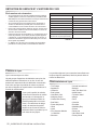
MAKE THE MOST OF YOUR
CARE & USE/INSTALLATION
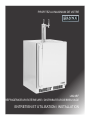
LM24BF
OUTDOOR REFRIGERATOR/BEVERAGE DISPENSER

2
CARE AND USE/INSTALLATION
NOTE
!
CAUTION
Safety information ...............................................................2
Unpacking your appliance ..................................................3
Warranty registration .....................................................3
Installing your appliance ......................................................4
Cabinet clearances .........................................................4
Leveling the appliance ....................................................4
Electrical connection ......................................................5
Product dimensions ............................................................6
Using your Electronic control .............................................8
Starting your appliance ...................................................8
Turning your appliance "ON" or "OFF" ...........................8
Adjusting the temperature ..............................................8
Beverage dispenser operation .......................................8
Alarms ............................................................................8
Door ajar ...................................................................8
Temperature sensor fault ..........................................8
High and Low temperature alarms ............................8
Alarm mute .. .................................................................9
Using your beverage dispenser........................................10
Shelving .......................................................................10
Tap equipment and assembly......................................11
CO2 regulator ................................................................15
Drain kit ........................................................................16
Care and cleaning ............................................................16
Cleaning the drain sump ...............................................16
Keg coupler cleaning ....................................................17
Faucet cleaning ............................................................17
Tap cleaning kit .............................................................18
Cleaning the beer line ...................................................18
Front grille .....................................................................18
Cabinet .........................................................................18
Interior ..........................................................................18
Long term storage / winterization .................................19
Stainless steel maintenance ............................................21
Energy saving tips ...........................................................21
Obtaining service .............................................................22
The Lynx Story .................................................................22
Troubleshooting ................................................................23
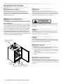
Important Safety Instructions
Contents
Warnings and safety instructions appearing in this guide
are not meant to cover all possible conditions and situa-
tions that may occur. Common sense, caution, and care
must be exercised when installing, maintaining, or operat-
ing this appliance.
Recognize Safety Symbols,
Words, and Labels.
!
WARNING
WARNING - You can be killed or seriously injured
if you do not follow these instructions.
CAUTION-Hazards or unsafe practices which could re-
sult in personal injury or property / product damage.
NOTE-Important information to help assure a problem
free installation and operation.
CONTENTS
!
WARNING
State of California Proposition 65 Warning:
This product contains one or more chemicals known
to the State of California to cause cancer.
!
WARNING
State of California Proposition 65 Warning:
This product contains one or more chemicals known
to the State of California to cause birth defects or
other reproductive harm..

3
CARE AND USE/INSTALLATION
NOTE
!
CAUTION
!
WARNING
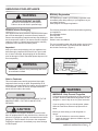
WARNING - Help Prevent Tragedies
Child entrapment and suffocation are not problems of
the past. Junked or abandoned refrigerators are still
dangerous - even if they sit out for "just a few hours".
If you are getting rid of your old refrigerator, please
follow the instructions below to help prevent acci-
dents.
Before you throw away your old refrigerator or
freezer:
• Take off the doors or remove the drawers.
• Leave the shelves in place so children may not
easily climb inside.
!
WARNING
WARNING - Dispose of the plastic bags which can
be a suffocation hazard.
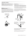
It is important you send in your warranty registration card
immediately after taking delivery of your appliance or you
can register online at
www.lynxgrills.com/support/registration
The following information will be required when registering
your appliance.
Service/Model Number
Serial Number
Date of Purchase
Dealer’s name and address
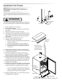
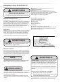
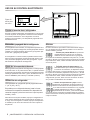
The service/model number and serial number can be found
on the serial plate which is located inside the cabinet on
the left side near the top. (Figure 1).
Figure 1
Your appliance has been packed for shipment with all parts
that could be damaged by movement securely fastened.
Remove internal packing materials and any tape holding in-
ternal components in place. The owners manual is shipped
inside the product in a plastic bag along with the warranty
registration card, and other accessory items.
Important
Keep your carton and packaging until your appliance has
been thoroughly inspected and found to be in good condi-
tion. If there is damage, the packaging will be needed as
proof of damage in transit. Afterwards please dispose of all
items responsibly.
Note to Customer
This merchandise was carefully packed and thoroughly
inspected before leaving our plant. Responsibility for its
safe delivery was assumed by the retailer upon acceptance
of the shipment. Claims for loss or damage sustained in
transit must be made to the retailer.
DO NOT RETURN DAMAGED MERCHANDISE TO THE
MANUFACTURER - FILE THE CLAIM WITH THE
RETAILER.
If the appliance was shipped, handled, or stored in other
than an upright position for any period of time, allow the ap-
pliance to sit upright for a period of at least 24 hours before
plugging in. This will assure oil returns to the compressor.
Plugging the appliance in immediately may cause damage
to internal parts.
!
WARNING
EXCESSIVE WEIGHT HAZARD
Use two or more people to move product.
Failure to do so can result in personal injury.
UNPACKING YOUR APPLIANCE
XXXXXXXXXXXXXX
XXXXXXXXXXXXXX
XXXXXXXXXXXX
Warranty Registration
Remove Interior Packaging

4
CARE AND USE/INSTALLATION
!
CAUTION
Leveling Legs
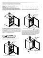
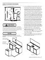
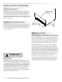
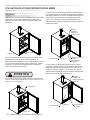
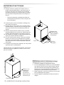
Select Location
Cabinet Clearance
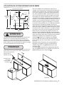
Front Grille
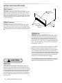
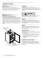
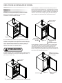
Figure 2
Front Leveling
Legs
Front Grille,
keep this area
open.
Rear
Leveling
Legs
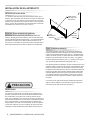
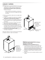
The proper location will ensure peak performance of your
appliance. We recommend a location where the unit will
be out of direct sunlight and away from heat sources. To
ensure your product performs to specications, the recom-
mended installation location temperature range is from 55
to 115°F (13 to 46°C).
Ventilation is required from the bottom front of the appli-
ance. Keep this area open and clear of any obstructions.
Adjacent cabinets and counter top can be installed around
the appliance as long as the front grille remains unobstruct-
ed.
Do not obstruct the front grille. The openings within the
front grille allow air to ow through the condenser heat ex-
changer. Restrictions to this air ow will result in increased
energy usage and loss of cooling capacity. For this reason
it is important this area not be obstructed and the grille
openings kept clean. Lynx Grills does not recommend the
use of a custom made grille as air ow may be restricted.
(See Figure 2).
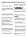
INSTALLING YOUR APPLIANCE
Adjustable legs at the front and rear corners of the appli-
ance should be set so the unit is rmly positioned on the
oor and level from side to side and front to back. The
overall height of your appliance may be adjusted between
the minimum, 33
3
⁄4" (85.7 cm), by turning the leveling leg in
(CW ↷) and the maximum, 34
3
⁄4" (88.3 cm) by turning the
leveling leg out (CCW ↶).
To adjust the leveling legs, place the appliance on a solid
surface and protect the oor beneath the legs to avoid
scratching the oor. With the assistance of another person,
lean the appliance back to access the front leveling legs.
Raise or lower the legs to the required dimension by turning
the legs. Repeat this process for the rear by tilting the appli-
ance forward using caution. On a level surface check the
appliance for levelness and adjust accordingly.
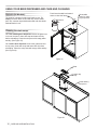
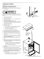
The front grille screws may be loosened and the grille ad-
justed to the desired height. When adjustment is complete
tighten the two front grille screws. (See Figure 5).

5
CARE AND USE/INSTALLATION
NOTE
Figure 6
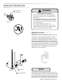
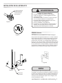
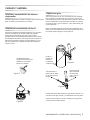
Ground Fault Circuit Interrupters (GFCI) are prone to nui-
sance tripping which will cause the appliance to shut down.
GFCI’s are generally not used on circuits with power equip-
ment that must run unattended for long periods of time, un-
less required to meet local building codes and ordinances.
A grounded 115 volt, 15 amp dedicated circuit is required.
This product is factory equipped with a power supply
cord that has a three-pronged, grounded plug. It must be
plugged into a mating grounding type receptacle in accor-
dance with the National Electrical Code and applicable lo-
cal codes and ordinances (see Figure 6). If the circuit does
not have a grounding type receptacle, it is the responsibility
and obligation of the customer to provide the proper power
supply. The third ground prong should not, under any cir-
cumstances, be cut or removed.
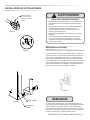
INSTALLING YOUR APPLIANCE
Front grille screw
Front grille
Figure 5
Figure 3
Figure 4
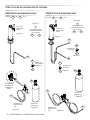
Do not remove
ground prong
Electrical Shock Hazard
• Do not use an extension cord with this appliance.
They can be hazardous and can degrade product
performance.
• This appliance should not, under any circumstanc-
es, be installed to an un-grounded electrical supply.
• Do not remove the grounding prong from the power
cord. (See Figure 3).
• Do not use an adapter. (See Figure 4).
• Do not splash or spray water from a hose on the
appliance. Doing so may cause an electrical shock,
which may result in severe injury or death.
!
WARNING
Electrical Connection

6
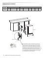
CARE AND USE/INSTALLATION
"A"
"B"
"C"
"D"
"E"
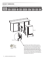
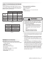
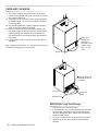
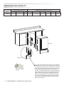
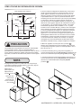
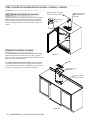
If necessary to gain clearance inside the rough-in
opening a hole can be cut through the adjacent cabi-
net and the power cord routed through this hole to a
power outlet. Another way to increase the available
opening depth is to recess the power outlet into the
rear wall to gain the thickness of the power cord plug.
Not all recessed outlet boxes will work for this applica-
tion as they are too narrow, but a recessed outlet box
equivalent to Arlington #DVFR1W is recommended for
this application, (see Figure 8).
Figure 8
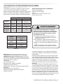
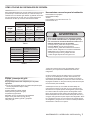
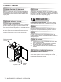
MODEL
ROUGH-IN OPENING DIMENSIONS CABINET DIMENSIONS
"A" "B" "C" "D" "E" "F" "G" "H" "J"
LM24BF
24"
(61 cm)
**34" to 35"
(86.4 to 88.9 cm)
*
23
7
⁄8"
(60.7 cm)
33
3
⁄4" to 34
3
⁄4"
(85.7 to 88.3 cm)
23
23
⁄32"
(60.2 cm)
26
3
⁄4"
(67.9 cm)
46
13
⁄32"
(117.9 cm)
26
3
⁄4"
(67.9 cm)
Figure 7
PRODUCT DIMENSIONS
Figure 7a

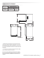
7
CARE AND USE/INSTALLATION
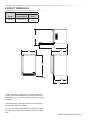
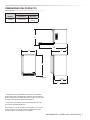
MODEL
PRODUCT DATA
ELECTRICAL
REQUIREMENTS#
PRODUCT
WEIGHT
LM24BF 115V/60Hz/15A
140 lbs
(63.6 kg)
* Depth dimension of rough-in opening may vary depend-
ing on each individual installation. To recess entire door "F"
dimension plus 1" (2.5 cm) for thickness of power cord plug
is required.
** Minimum rough-in opening required is to be larger than
the adjusted height of the cabinet.
# A grounded 15 amp dedicated circuit is required. Follow
all local building codes when installing electrical and appli-
ance.
PRODUCT DIMENSIONS
"F"
21
1
⁄2"
(54.6 cm)
"D"
"E"
"H"
"J"
"G"
Figure 9

8
CARE AND USE/INSTALLATION
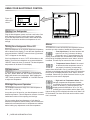
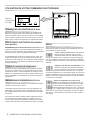
Beverage Dispenser Operation
USING YOUR ELECTRONIC CONTROL
Plug the beer dispenser power cord into a wall outlet. Your
beer dispenser will begin cooling after power is applied.
If your beer dispenser does not start, check that the beer
dispenser is turned on and the set temperature is cold
enough.
If the beer dispenser is on, the beer dispenser temperature
will be shown on the display. To turn the beer dispenser off,
press and hold the "ON/OFF" button for three (3) seconds.
"OFF" will appear on the display.
If the beer dispenser is not on, "OFF" will be shown on the
display. To turn the beer dispenser on, press and hold the
"ON/OFF" button for three (3) seconds. The beer dispenser
temperature will be shown on the display.
To set the beer dispenser temperature, press and hold
the "SET" button. When the "SET" button is pressed, the
display will show the set temperature. While holding the
"SET" button, press the "WARMER" or "COLDER" buttons
to adjust set temperature.
The available temperature range of the beer dispenser is
34° to 46°F (1° to 8° C).
It may take up to 24 hours for your beer dispenser to reach
desired temperature. This will depend on amount of content
loaded and number of door opening and closings.
For best results allow beer dispenser to "pull down" to
desired set temperature before loading. Once contents are
loaded, allow at least 48 hours for temperature to stabilize
before making any adjustments to the set temperature.
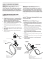
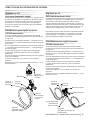
• Temperature Sensor Fault: If the control-
ler detects that the temperature sensor is
not properly functioning, a temperature
sensor alarm will sound in one (1) second intervals. "E1"
will ash on the display panel and the Alarm LED located at
the top left of the display below the word "Alarm" will be il-
luminated. Please call Lynx Grills Customer Service or your
dealer if this error code is displayed.
• High and Low Temperature Alarm: If the
storage compartment temperature deviates
excessively from the set-point temperature, the
alarm will sound in (1) second intervals. The
display panel will ash either "Hi" or "Lo" de-
pending upon the condition and the Alarm LED
light at the top left of the display below the word "Alarm" will
be illuminated. The alarm will remain active until the condi-
tion is corrected.
Set
Colder Warmer
ON/OFF
Press and Hold Press and Hold
Alarm
F
Figure 10
close-up of
control
Your electronic control will monitor beer dispenser function
and alert you with a series of audible and visual alarms.
• Door Ajar Alarm: If the door has been left
open for over ve (5) minutes, the alarm
will sound in one (1) second intervals. The
display panel will ash "do" and the Alarm LED located at
the top left of the display below the word "Alarm" will be il-
luminated. This will stop as soon as the door is closed.
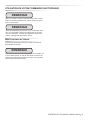
Figure 11
Starting Your Refrigerator
Turning Your Refrigerator ON or OFF
Set temperature
Alarms

9
CARE AND USE/INSTALLATION
USING YOUR ELECTRONIC CONTROL
NOTE
Press any key to mute the audible portion of an alarm.
This action will only mute the alarm. If the condition that
caused the alarm continues, the alarm code will continue to
ash and will sound for 20 seconds every 60 minutes.
NOTE
NOTE
After a high temperature alarm condition, check all perish-
ables to ensure they are safe for consumption.
The temperature alarm may occur as a result of high usage
or introduction of warm contents to the storage compart-
ment. If the temperature alarm continues to occur, your unit
may require service.
Alarm Mute

10
CARE AND USE/INSTALLATION
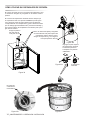
The unit is shipped with the (2) shelves taped in place in
the upper and the lower shelf positions. Remove them from
the refrigerator and arrange them as follows when setting
up your unit.
If you are not serving beer on tap, your keg dispenser can
be used as a refrigerator by placing both shelves on the
mounting brackets as shown in Figure 13. The shelves are
marked upper and lower, The upper shelf should be placed
in the top shelf position and the shelf marked lower should
be placed in the bottom shelf position.
Stored upper and
lower shelves
on side
Two shelves
installed
Figure 12
If you are using a quarter barrel of beer, you can add shelf
space for keeping your mugs chilled. The quarter barrel
must set on the oor, it cannot t on the shelf, see
Figure 14. Be sure the white oor plate is in the bottom of
the interior compartment before positioning the barrel.
Figure 14
Half barrel (keg)
Installed upper
shelf above
barrel
Figure 13
Quarter barrel
Figure 15
If you are using a half barrel (keg) or (2) 1/6 barrels, place
the two shelves on the right side of the keg dispenser on
the two mounting hooks for storage. (See Figure 15). Be
sure the white oor plate is in the bottom of the interior
compartment before positioning the barrel(s).
Two shelves
White oor plate
White oor plate
USING YOUR BEVERAGE DISPENSER
Stored lower shelf
If you are using the appliance as a refrigerator for per-
ishable foods, the set-point temperature should be set
between 34°F and 42° F (1.2° C and 5.7° C).
!
CAUTION
Shelving

11
CARE AND USE/INSTALLATION
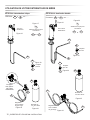
USING YOUR BEVERAGE DISPENSER
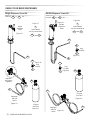
Your dispensing kit includes the following parts:
Polished stainless steel tower with clear beer line (single
or double dispense)
Tower Gasket
Phillips oval head screws
Knob for Tower (Faucet Handle)
Keg coupler(s)
CO2 regulator with red gas line(s) attached
Empty 5 pound CO2 tank
Plastic clamp(s) large and small
Faucet wrench
Tools required for installation:
Flat bladed screwdriver
Phillips screwdriver
Pliers
Adjustable wrench or a 1
1
⁄8" open end wrench
1
⁄2" open end wrench
Barrel Sizes
1/6 barrel 1/4 Barrel 1/2 Barrel
Height
23
5
⁄16"
(59.2 cm)
14
13
⁄16"
(37.6 cm)
23
5
⁄16"
(59.2 cm)
Diameter
9
1
⁄4"
(23.5 cm)
17"
(43.2 cm)
17" to 17
1
⁄4"
(43.2 to 43 cm)
Gallons 5.16 7.75 15.5
#12 ounce
Glasses
60 82 163
This beer dispensing unit will support one half (
1
⁄2) barrel
or one quarter (
1
⁄4) barrel. The double draft tower units can
support two sixth (
1
⁄6) barrels of beer. See chart below for
quantity of beer in each barrel size.
Table A
Table B
Keg Size
#of kegs per
5 pound CO2 Tank
5 gallon Corny 15 to 22
1/6 barrel 14 to 21
1/4 Barrel 10 to 14
1/2 Barrel 5 to 7
CO2 can be dangerous. If it becomes difcult to
breathe and/or your head starts to ache, a high
concentration of carbon dioxide may be present.
Leave the area immediately.
• The CO2 tank must always be connected to the
regulator. Never connect the tank to the keg.
• The CO2 tank must be securely mounted in the
upright position. Secure it with the chain pro-
vided.
• Never drop or throw the CO2 tank.
• Keep the CO2 tank away from heat.
• Ventilate the area after a CO2 leak.
!
WARNING
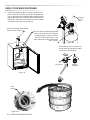
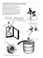
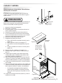
1. Remove shelving and packaged components from the
interior of the refrigerator before beginning the assem-
bly process.
2. Take your empty 5 pound CO2 tank to your local gas
supply dealer to be lled. You can usually nd them in
your "yellow pages" under "Welding Supply" or "Fire
Protection". One 5 pound tank can process many kegs
(see Table B).
3. Tower mounting (if you are installing the unit under a
counter skip to step 4). If you are mounting the tower
directly to the top of the refrigerator, rst remove the
four screws from the top of the refrigerator. Remove the
foam plug from the large hole in the top of the refrigera-
tor. Feed the clear beer line through the tower gasket
and the large hole in the refrigerator top. Align the 4
holes in the tower with the 4 holes in the refrigerator
top and secure the tower with the 4 screws removed
previously. Skip to step 5.
Tap Equipment and Assembly

12
CARE AND USE/INSTALLATION
B
B
B
B
5 Pound
CO2 Tank
5 Pound
CO2 Tank
Figure 19
Figure 25
A
A
A
A
A
A
C
C
C
C
C
C
Regulator
with red
airline
Regulator
with red
airline
Keg
Coupler
Keg
Coupler
Keg
Coupler
Single
Dispense
Tower
Double
Dispense
Tower
A
C
Hose clamps
use for connections
and
A
C
Hose clamps
use for connections
and
A A
Connect to ,etc........
A A
Connect to ,etc........
Figure 16
Figure 17
Figure 18
Figure 23
Figure 24
Figure 26
Figure 22
Figure 20
Figure 21
Optional
dual gauge
regulator
USING YOUR BEER DISPENSER
Single Dispense Tower Kit Double Dispense Tower Kit

13
CARE AND USE/INSTALLATION
A
C
B
4. If you are installing your keg refrigerator under a coun-
ter you will need to drill 5 holes in the counter top to
mount the tower. The rst hole is a 1
1
⁄2" diameter hole
located at the center of the tower for the beer line, lo-
cate approximately 13
1
⁄2" (34.3 cm) from the front edge
of the counter top (based on a counter top depth of
25
5
⁄16"). Next drill the 4 tower mounting holes per the di-
mensions in Figure 27. The hole diameter is dependent
on the counter top material and if screw anchors are
required. The screws supplied are in the literature pack
and are a #10 x 1" type AB stainless steel screw. Mark
and cut the rectangular cutout for the drain sump. After
the holes are drilled and the keg refrigerator is in place
under the counter top feed the beer line through the
tower gasket, the 1
1
⁄2" hole in the counter top and the
hole in the top of the keg refrigerator. Mount the tower
to the counter top with the 4 screws provided. Place
the counter top drain sump, from the literature pack, in
the rectangular hole with the radius cutout to the rear
around the tower and place the grate in the sump.
5. Mount the regulator to the CO2 tank (connection ).
Note that the regulator has left hand threads and has to
be turned counterclockwise to tighten. Tighten with the
adjustable wrench or the 1
1
⁄8" open end wrench.
6. Connect the red air line(s) from the regulator to the
large air line tting on the keg coupler with a large
hose clamp (connection ).
7. Connect the clear beer line from the tower to the small
air line tting on the keg coupler with a small hose
clamp (connection ).
8. Locate the CO2 tank in the corner of the refrigerator as
shown in Figure 30 and secure with the chain. Close
the faucet handle on the tower.
Diameter
to suit
Rear of counter top
6
1
⁄8"
(15.6 cm)
12
1
⁄4"
(31.1 cm)
2
7
⁄8"
(7.3 cm)
4
1
⁄4"
(10.8 cm)
6
3
⁄8"
(16.2 cm)
1
3
⁄8"
(3.5 cm)
typical
1
1
⁄2 (38 mm)
Diameter
counter
top depth
25
5
⁄16"
(64.3 cm)
1
⁄4" (6 mm)
radii,
typical
Figure 27
Figure 28
Figure 29
Grate from top of
beer dispenser
Counter top
sump from
literature pack
Tower
!
CAUTION
The cutout dimensions shown in Figure 27 are based on
a 25
5
⁄16" (64.3 cm) deep counter top. Your counter top may
be different than this and require other front to back dimen-
sioning. Refer to the product dimensions on pages 6 and 7
when determining the required dimensions.
NOTE
Your tower kit may or may not come with a "sit on top"
sump option. To use it please follow the instructions in the
tower kit.
USING YOUR BEER DISPENSER

14
CARE AND USE/INSTALLATION
Figure 31
Figure 31a
Rotate the top of the coupler coun-
ter clockwise to extend the coupler
to the to the "OFF"position.
Coupler
extended
9. Hooking up the keg coupler to the keg: Verify the cou-
pler is in the "OFF" position (see Figure 31a).Align the
lugs on the keg with the corresponding openings on the
keg coupler and turn clockwise until the coupler stops
(about 90°). Push down and twist the top of the coupler
clockwise to allow gas to enter the keg.
Figure 30
Push faucet handle back toward
tower to close the faucet
Chain-The chain is fastened and taped
to the top of the interior liner. Remove
the tape and secure the CO2 tank in
place in the back right corner. Loop
chain around top of tank and connect
with "S" hook.
Figure 30a
Connect
with "S"
hook
USING YOUR BEER DISPENSER
Lugs
on keg
Figure 31b

15
CARE AND USE/INSTALLATION
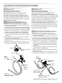
Your beer dispenser comes equipped with a 5 pound CO2
tank and a dual gauge regulator. The lower gauge should
be reading approximately 750 psi (52 bar) when the tank is
properly lled and the tank is not in the refrigerator (at room
temperature). The tank will read less when chilled. Use this
lower gauge as an indicator of how much CO � you have left
in the tank.
The upper gauge reads the pressure being supplied to the
beer keg. Follow the procedure below to adjust the pres-
sure to 12 - 14 psi (0.8 to 1 bar) for lager beer or 9 - 12 psi
(0.6 to 0.8 bar) for ale's.
1. Close the shutoff valves at the bottom of the regulator.
2. Be sure the faucet handle is closed on the tower (see
Figure 30).
3. Loosen the lock nut by turning counterclockwise us-
ing the
1
⁄2" open end wrench until loose, this will allow
adjustment of the pressure adjustment screw.
4. With the at bladed screwdriver turn the adjustment
screw clockwise to increase the pressure or counter-
clockwise to decrease the pressure.
5. Open the shutoff valve on the bottom of the regula-
tor. The gauge reading may drop but will return very
quickly.
6. Pull the ring on the keg coupler to allow the gas to ow
momentarily.
7. Make any ne adjustments if necessary with the adjust-
ment screw.
8. Tighten the locknut with the
1
⁄2" open end wrench by
turning clockwise.
Your beer dispenser comes equipped with a 5 pound CO2
tank and a single gauge regulator. The gauge reads the
pressure being supplied to the beer keg. Follow the proce-
dure below to adjust the pressure to 12 - 14 psi (0.8 to 1
bar) for lager beer or 9 - 12 psi (0.6 to 0.8 bar) for ale's.
1. Close the shutoff valve at the bottom of the regulator.
2. Be sure the faucet handle is closed on the tower (see
Figure 30).
3. Loosen the lock nut by turning ↶ counterclockwise us-
ing the
1
⁄2" open end wrench until loose, this will allow
adjustment of the pressure adjustment screw.
4. With the at bladed screwdriver turn the adjustment
screw ↷ clockwise to increase the pressure or ↶ coun-
terclockwise to decrease the pressure.
5. Open the shutoff valve on the bottom of the regula-
tor. The gauge reading may drop but will return very
quickly.
6. Pull the ring on the keg coupler to allow the gas to ow
momentarily.
7. Make any ne adjustments if necessary with the adjust-
ment screw.
8. Tighten the locknut with the
1
⁄2" open end wrench by
turning clockwise ↷.
Ring on
keg
coupler
Figure 33
(Regulator for Single
Dispense Tower)
Figure 34
(Regulator for Double
Dispense Tower)
Figure 32
(2) shutoff
valves (closed
position shown)
Upper Gauge
Pressure Gauge
Lower Gauge
Pressure
Adjustment
Screw
Lock Nut
USING YOUR BEER DISPENSER
Pressure
Adjustment
Screw
Lock Nut
shutoff valve
(closed posi-
tion shown)
CO2 Regulator (Single Dispense Tower)
To adjust the pressure (Single Gauge):
CO2 Regulator (Double Dispense Tower)
To adjust the pressure (Upper Gauge):

16
CARE AND USE/INSTALLATION
Figure 35
The drain kit is shipped in place and ready to use. To
empty: Pull drain hose out of bottle cap, remove bottle
from unit, unscrew cap and discard waste and rinse bottle.
Reinstall bottle in unit.
Unscrew
cap
Removable
grate for clean-
ing sump area
On a free standing beer dispenser remove the grate from
in front of the tower, clean with soap and water and dry
before reinstalling. Clean the sump area with soapy water
and dry. (See Figure 35).
On a built in beer dispenser remove the grate and coun-
ter top sump, clean with soap and water and dry before
reinstalling. Clean the sump area with soapy water and dry.
(See Figure 36).
Grate
Counter top
sump
Clean and dry
sump area
Figure 36
Push faucet handle back toward
tower to close the faucet
USING YOUR BEER DISPENSER AND CARE AND CLEANING
Drain kit (All Models):
Cleaning the drain sump:

17
CARE AND USE/INSTALLATION
Turn off the gas supply with the shutoff valve(s) under the
regulator (see Figure 33 or Figure 34) and open the faucet
to relieve the pressure. To remove the faucet from the tow-
er use the spanner wrench provided. Place the pin on the
wrench into the hole on the faucet collar and turn clockwise
↷ to remove the faucet. (See Figure 39).
Remove the knurled cap from the faucet body just below
the handle and pull the handle assembly from the faucet.
This will allow the shaft to be removed from the back of the
faucet, see Figure 40.
Soak all faucet parts in hot clear water or a solution of hot
water and a sanitizing solution. Do not use soap. Rinse
thoroughly with clean water.
Reassemble faucet, assemble faucet to tower (be sure
faucet is in off position), and turn on gas valve.
Figure 39
Figure 40
After removing the
handle the shaft will
slide out the back of the
faucet
Unscrew knurled
cap on faucet body
and remove handle
assembly
Place pin on
wrench into hole
in faucet collar.
CARE AND CLEANING
Remove the keg coupler from the keg if necessary. Close
the gas valve(s) below the regulator, remove both the red
gas line(s) and clear beer line(s) from the keg coupler(s) by
removing the plastic hose clamps (See Figure 37). Soak
and brush the keg coupler in hot water or a sanitizing solu-
tion. Rinse thoroughly with clean water. Dry all parts and
reassemble.
The dispensing system needs to be cleaned between
usage to prevent spoilage and/or foul taste in your beer.
Figure 38
Figure 37
Hose clamps can be
released by a lateral
movement to the head.
Cleaning and Maintaining Dispensing System
Keg Coupler Cleaning
Faucet Cleaning

18
CARE AND USE/INSTALLATION
CARE AND CLEANING
!
CAUTION
SHOCK HAZARD: Disconnect electrical power from the
appliance before cleaning with soap and water.
Figure 41
This is an optional item (part number 42242373) Kit in-
cludes everything to quickly clean tap. Includes cleaning
solution, pump, mixing bottle, brush and wrench.
Front Grille
Cabinet
Interior
Care of Appliance
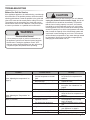
In the Event of a Power Failure
Cleaning the beer line
Tap Cleaning Kit
The stainless steel cabinet can be washed with either a
mild soap and water and thoroughly rinsed with clear water.
NEVER use abrasive scouring cleaners. Dry thoroughly
with a terry towel.
Wash interior compartment with mild soap and water. Do
NOT use an abrasive cleaner, solvent, polish cleaner or
undiluted detergent.
Avoid leaning on the door, you may bend the door hinges
or tip the appliance.
1. Exercise caution when sweeping, vacuuming or mop-
ping near the front of the appliance. Damage to the
grille can occur.
2. Periodically clean the interior of the appliance as
needed.
If a power failure occurs, try to correct it as soon as pos-
sible. Minimize the number of door openings while the
power is off so as not to adversely affect the appliance's
temperature.
Be sure that nothing obstructs the required air ow open-
ings in front of the cabinet. At least once or twice a year,
brush or vacuum lint and dirt from the front grille area (see
page 4).
(using tap cleaning kit 42242373):
With the faucet removed from the tower (see page 17) and
the keg coupler removed from the keg (see page 17), place
the end of the beer line in a pail or pan. Secure the pump
to the tower with the coupler nut provided on the pump
assembly. Pump a sanitizer / cleaner through the beer line
until clean. Rinse the pump bottle with hot water, and using
the pump, ush the beer line 2 or 3 times with clean hot
water.
Pail or pan
beer line
Pump connected
to tower

19
CARE AND USE/INSTALLATION
CARE AND CLEANING
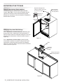
Long Term Storage/Winterization
Time to Winterize, when the daily low ambient temperature
is at or below 38° F.
1. Turn unit off, (see page 8).
2. Remove all contents.
3. If necessary, move the unit so you can gain access to
the rear of the product.
4. Unplug the unit from the power outlet.
5. It is also recommended that the power to the outlet be
turned-off if the circuit is not required for other items
during the Winter season.
6. Shut-off CO2 tank valve.
7. Drain beer line(s)
8. Disassemble faucet and clean, (see page 17).
9. Soak and clean Sankey Low-Boy tap, (see page 17).
10. When cleaning unit pay particular attention to any
cracks and crevices that may have accumulated dirt
and debris.
11. Remove the front toe-grille, (see Figure 42 and Figure
43), and use a brush and vacuum to clean dirt and
debris from beneath the unit.
12. Thoroughly clean the toe-grille and re-install on the
unit.
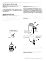
13. Remove the rear access cover, (see Figure 44), and
use a brush and vacuum to clean dirt and debris from
the machine compartment.
14. Thoroughly clean the rear access cover and re-install
on the unit.
15. Wipe down all interior surfaces with anti-bacterial
cleaner to be followed with clean rinse water to remove
any residual chemicals which could cause staining. Do
not use any abrasive cleaners or scouring pads.
16. Leave door open and allow to completely dry out be-
fore closing door.
!
CAUTION
Operating of the unit at ambient temperatures below the
recommended Winterization temperature will void your war-
ranty.
a. Remove Sankey tap (keg coupler), (see page 17).
b. Remove faucet on tower, (see page 17).
c. Beer lines will gravity drain.
d. Clean beer line tubing, (see page 18).
• If the plastic defrost drain pan located under the
compressor contains water, use a sponge to re-
move as much water as possible
• Remove plastic oor protector and stainless steel
lower edge guard to clean underneath.
Front grille screw
Front grille
Figure 42
Remove oor
protector and
edge guard
and clean
Floor protector
Edge
guard
Figure 43
Figure 43a
Grille
Spacer
Clean out
behind
grille

20
CARE AND USE/INSTALLATION
CARE AND CLEANING
Start-Up After Long-Term Storage:
1. Connect the unit to electrical power.
2. If stored outside, it is recommended that the unit again
be thoroughly inspected per the storage instructions
above to address any dirt or debris from the weather
and/or animals/insects.
3. Turn unit on and conrm your desired control settings.
4. Allow 24-hrs for the unit to stabilize before loading
contents.
17. Thoroughly clean the door gasket with anti-bacterial
cleaner to be followed with clean rinse water to remove
any residual chemicals.
18. Thoroughly clean the exterior with a cleaner approved
for stainless steel . Do not use any abrasive cleaners
or scouring pads.
19. Any mounting hardware / fasteners that are showing
signs of corrosion should be replaced.
20. Once the exterior has been thoroughly cleaned, you
may want to apply a coating of car wax to help protect
against spotting from moisture, dirt, and debris that
may accumulate on the surfaces during the Winteriza-
tion period.
21. Do not place a cover on the unit, as this can trap con-
densation.
After completion of the above, you may choose to store the
unit indoors, although this is not required.
Remove 11
screws from
around the
perimeter of the
access cover
with a
5
⁄16" nut
driver.
Figure 44
Figure 45
Soak up water from
plastic drain pan if
necessary
Clean out
debris
Access cover
Page is loading ...
Page is loading ...
Page is loading ...
Page is loading ...
Page is loading ...
Page is loading ...
Page is loading ...
Page is loading ...
Page is loading ...
Page is loading ...
Page is loading ...
Page is loading ...
Page is loading ...
Page is loading ...
Page is loading ...
Page is loading ...
Page is loading ...
Page is loading ...
Page is loading ...
Page is loading ...
Page is loading ...
Page is loading ...
Page is loading ...
Page is loading ...
Page is loading ...
Page is loading ...
Page is loading ...
Page is loading ...
Page is loading ...
Page is loading ...
Page is loading ...
Page is loading ...
Page is loading ...
Page is loading ...
Page is loading ...
Page is loading ...
Page is loading ...
Page is loading ...
Page is loading ...
Page is loading ...
Page is loading ...
Page is loading ...
Page is loading ...
Page is loading ...
Page is loading ...
Page is loading ...
Page is loading ...
Page is loading ...
Page is loading ...
Page is loading ...
Page is loading ...
Page is loading ...
-
 1
1
-
 2
2
-
 3
3
-
 4
4
-
 5
5
-
 6
6
-
 7
7
-
 8
8
-
 9
9
-
 10
10
-
 11
11
-
 12
12
-
 13
13
-
 14
14
-
 15
15
-
 16
16
-
 17
17
-
 18
18
-
 19
19
-
 20
20
-
 21
21
-
 22
22
-
 23
23
-
 24
24
-
 25
25
-
 26
26
-
 27
27
-
 28
28
-
 29
29
-
 30
30
-
 31
31
-
 32
32
-
 33
33
-
 34
34
-
 35
35
-
 36
36
-
 37
37
-
 38
38
-
 39
39
-
 40
40
-
 41
41
-
 42
42
-
 43
43
-
 44
44
-
 45
45
-
 46
46
-
 47
47
-
 48
48
-
 49
49
-
 50
50
-
 51
51
-
 52
52
-
 53
53
-
 54
54
-
 55
55
-
 56
56
-
 57
57
-
 58
58
-
 59
59
-
 60
60
-
 61
61
-
 62
62
-
 63
63
-
 64
64
-
 65
65
-
 66
66
-
 67
67
-
 68
68
-
 69
69
-
 70
70
-
 71
71
-
 72
72


Ask a question and I''ll find the answer in the document
Finding information in a document is now easier with AI
in other languages
Related papers
Other documents
-
Marvel ML24BS Owner's manual
-
Fire Magic Outdoor Rated Kegerator User manual
-
DCS RF24BTR1 Installation guide
-
DCS RF24TR1 Owner's manual
-
Marvel MO24BNSMRS Installation guide
-
-
Twin Eagles TEBK242-F User manual
-
AGA marvel 6OHK Troubleshooting guide
-
Magic Chef MCKC490B2 Owner's manual
-
Danby DKC644BLS Owner's manual