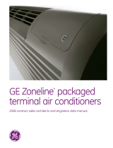
GE AZ41E12EAC User guide

Type
User guide
Zoneline
®
Packaged Terminal Air Conditioners
HIGHLY EFFICIENT.
AMAZINGLY QUIET.
2
WHY GE ZONELINE
®
TERMINAL AIR CONDITIONERS?
Engineered for year-round comfort. Easy to operate. Whisper quiet. GE Zoneline
units stand out as the premium choice for virtually any application – even in
extreme conditions. As one of the most energy-effi cient packaged terminal air
conditioners in the industry, Zoneline keeps costs low and profi ts high.
3
LOW ENERGY COSTS.
ONGOING SAVINGS.
Zonelines are some of the most
energy effi cient PTAC/PTHP in the
industry. The more energy effi cient
the unit, the lower the utility bill –
and that means a better bottom
line for you.
OVER A HALF-CENTURY
OF RELIABILITY
Since GE fi rst introduced Zonelines
in 1961, customers across the
country have depended on them
for reliable operation and long-
lasting performance.
PEACE AND QUIET
Cross-fl ow blower and two fan
motors create less noise to ensure
all-around comfort – without
all the commotion.
4
KEY FEATURES
*Available on 7000, 9000 and 12000 BTU models.
ELECTRONIC TOUCH CONTROLS
Microcomputer-touch controls with a touch pad and LED
readout give the user better control over the temperature.
ELECTRONIC TEMPERATURE LIMITING
Heating and cooling temperature can be limited to prevent
expensive over-cooling or over-heating. Heating and cooling
limits are also automatically set so seasonal adjustment is
not necessary.
CROSS-FLOW BLOWER
A unique cylindrical shape causes the air to move and
respond with equal power, but with less noise than
traditional fans.
THE DRY AIR 25*
Using GE’s exclusive patented Dinh
®
Dehumidifi er Heat
Pipe from Heat Pipe Technology, Inc., this innovative
technology removes 25% more moisture from the air than
standard GE packaged terminal air conditioners. Perfect
for high-humidity climates.
HEAT SENTINEL
If the temperature of an unoccupied room reaches 85,°
Zoneline units provide automatic protection against
over-heating by switching on the unit to cool the room.
FREEZE SENTINEL
Protects against damage caused by freezing temperatures in
unoccupied rooms, regardless of unit setting.
OPTIONAL CORROSION TREATMENT
Placed on the outdoor coil and other components to reduce
the effects of corrosive environments and extend the life of
the unit.
TWO FAN MOTORS
Separate motors for indoor and outdoor fans assure quiet
operation and comfortable conditions.
“SMARTFAN” CYCLE SELECTION
Automatically selects “fan cycle” for heat and “fan
continuous” for cooling to provide better guest comfort and
eliminate the need for changing the fan switch seasonally.
5
6
RESISTANCE HEAT LINE UP
DELUXE DRY AIR 25
AZ41E12DAP
11,200/11,000 BTU,
10.8/10.8 EER, 230/208 Volts
AZ41E09DAP
9,200/8,800 BTU,
11.5/11.5 EER, 230/208 Volts
AZ41E07DAP
6,500/6,300 BTU,
11.7/11.7 EER, 230/208 Volts
AZ41E12EAP
11,200 BTU, 10.8 EER, 265 Volts
AZ41E09EAP
9,200 BTU, 11.5 EER, 265 Volts
AZ41E07EAP
6,500 BTU, 11.7 EER, 265 Volts
DELUXE 4100 SERIES*
AZ41E15DAB
14,300/14,000 BTU,
10.3/10.3 EER, 230/208 Volts
AZ41E12DAB
11,800/11,500 BTU,
11.1/11.1 EER, 230/208 Volts
AZ41E09DAB
9,700/9,600 BTU,
12.0/12.0 EER, 230/208 Volts
AZ41E07DAB
7,200/6,900 BTU,
12.3/12.3 EER, 230/208 Volts
AZ41E15EAB
14,300 BTU, 10.3 EER, 265 Volts
AZ41E12EAB
11,800 BTU, 11.1 EER, 265 Volts
AZ41E09EAB
9,700 BTU, 12.0 EER, 265 Volts
AZ41E07EAB
7,200 BTU, 12.3 EER, 265 Volts
Specifications subject to change.
*Models with corrosion treatment are also available. BTUH, wattage and EER may vary on those models.
**Models with corrosion treatment and ICR are also available. BTUH, wattage and EER may vary on those models.
7
HEAT PUMP LINE UP
DELUXE 6100 SERIES**
AZ61H15DAB
14,500/14,200 cooling BTU,
13,500/13,400 heating BTU,
10.6/10.6 EER, 230/208 Volts
AZ61H12DAB
11,700/11,600 cooling BTU,
10,600/10,400 heating BTU,
11.6/11.6 EER, 230/208 Volts
AZ61H09DAB
9,400/9,100 cooling BTU,
8,300/8,100 heating BTU,
12.2/12.2 EER, 230/208 Volts
AZ61H07DAB
7,100/6,900 cooling BTU,
6,200/6,100 heating BTU,
13.0/13.0 EER, 230/208 Volts
AZ61H15EAB
14,400 cooling BTU,
13,500 heating BTU,
10.6 EER, 265 Volts
AZ61H12EAB
11,700 cooling BTU,
10,700 heating BTU,
11.6 EER, 265 Volts
AZ61H09EAB
9,400 cooling BTU,
8,100 heating BTU,
12.2 EER, 265 Volts
AZ61H07EAB
7,000 cooling BTU,
6,200 heating BTU,
12.8 EER, 265 Volts
ALL MODELS INCLUDE:
Tactile touchpad controls
Solid-state thermostat
3-position vent control
Automatic indoor frost control
Cross-fl ow blower
Freeze Sentinel and Heat Sentinel
Remote thermostat capability
HEAT PUMP UNITS INCLUDE:
Staged heating
Heat pump with resistance heat back-up
Heat pump with supplemental resistance heat
Electric resistance heat lockout
Reverse cycle defrost
8
Specifications subject to change.
ZONELINE
®
PTAC CHART
DELUXE SERIES –
COOLING & ELECTRIC HEAT
230/208V MODELS AZ41E07D AZ41E09D AZ41E12D AZ41E15D
Cooling BTUH 7,200/6,900 9,700/9,600 11,800/11,500 14,300/14,000
EER (BTU/Watt) 12.3/12.3 12.0/12.0 11.1/11.1 10.3/10.3
Dehumidification Pts/Hr 1.7 2.7 3.5 4.6
Refrigerant type R-410A R-410A R-410A R-410A
CFM, indoor fan high 290 340 420 409
CFM, indoor fan low 218 229 323 324
Vent CFM (full open/partial open) 50/40 70/45 75/45 75/45
Power factor 89% 93% 93% 90%/92%
Sensible heat ratio @ 230 volts 80% 75% 70% 70%
Watts 580/560 805/795 1060/1035 1370/1350
Cooling Amperes, F.L. 2.8/3.0 3.6/3.9 4.7/5.1 6.7/7.2
Amperes, L.R. 19.0 21.0 29.5 31.0
Weight (Net/Ship) 89.5/102.5 99.9/112.9 99.4/112.4 100.3/113.3
265V MODELS AZ41E07E AZ41E09E AZ41E12E AZ41E15E
Cooling BTUH 7,200 9,700 11,800 14,300
EER (BTU/Watt) 12.3 12.0 11.1 10.3
Dehumidification Pts/Hr 1.7 2.7 3.5 4.6
CFM, indoor fan high 290 340 420 406
CFM, indoor fan low 215 229 323 324
Vent CFM (full open/partial open) 50/40 70/45 75/45 75/45
Power factor 90% 91% 92% 92%
Sensible heat ratio @ 265 volts 80% 75% 70% 70%
Watts 580 805 1025 1385
Cooling Amperes, F.L. 2.4 3.2 4.1 5.7
Amperes, L.R. 12.0 16.5 23.5 26.0
Weight (Net/Ship) 91.3/104.3 101.2/114.2 99.9/112.9 101.0/114.0
4100 SERIES UNITS
9
AZ41E07DAP AZ41E09DAP AZ41E12DAP
6,500/6,300 9,200/8,800 11,200/11,000
11.7/11.7 11.5/11.5 10.8/10.8
2.3 3.4 4.4
R-410A R-410A R-410A
220 280 330
190 208 270
50/40 70/45 75/45
86%/87% 92% 92%
60% 60% 60%
555/535 790/765 1035/1015
2.8/3.0 3.6/3.9 4.7/5.1
19.0 21.0 29.5
97.0/110.0 105.2/118.2 105.4/118.4
AZ41E07EAP AZ41E09EAP AZ41E12EAP
6,500 9,200 11,200
11.7 11.5 10.8
2.3 3.4 4.4
220 280 330
190 208 270
50/40 70/45 75/45
87% 91% 92%
60% 75% 60%
555 795 1020
2.4 3.2 4.1
12.0 16.5 23.5
97.4/110.5 104.9/117.9 108.0/121.0
DRY AIR 25
10
*Corrosion model BTUH and watts may vary.
**ICR adds 3 pounds to unit weight
Specifications subject to change.
DELUXE SERIES –
HEAT PUMP UNITS*
230/208V MODELS AZ61H07D AZ61H09D AZ61H12D AZ61H15D
Cooling BTUH 7,100/6,900 9,400/9,100 11,700/11,600 14,500/14,200
EER (BTU/Watt) 13.0/13.0 12.2/12.2 11.6/11.6 10.6/10.8
Dehumidification Pts/Hr 1.7 2.7 3.5 4.5
Refrigerant type R-410A R-410A R-410A R-410A
CFM, indoor fan high 340 360 370 370
CFM, indoor fan low 194 212 284 290
Vent CFM (full open/partial open) 50/40 70/45 75/45 75/45
Power factor 91% 92% 92% 91%/92%
Sensible heat ratio @ 230 volts 85% 75% 70% 65%
Cooling Watts 545/525 755/740 985/965 1,360/1,335
Cooling Amperes, F.L. 2.6/2.8 3.5/3.8 4.6/5.0 6.3/6.8
Amperes, L.R. 19.0 21.0 29.5 31.0
Reverse cycle heat BTUH 6,200/6,100 8,300/8,100 10,600/10,400 13,500/13,400
COP 3.9/3.9 3.7/3.7 3.6/3.6 3.3/3.3
Heating Watts 465/445 650/635 855/835 1,165/1,120
Heating Amperes 2.2/2.4 3.1/3.3 4.1/4.5 5.8/6.3
Weight (Net/Ship) 94.1/107.1 101.4/114.4 102.1/115.1 100.8/113.8
265V MODELS AZ61H07E AZ61H09E AZ61H12E AZ61H15E
Cooling BTUH 7,000 9,400 11,700 14,400
EER (BTU/Watt) 12.8 12.2 11.6 10.6
Dehumidification Pts/Hr 1.7 2.7 3.5 4.5
Refrigerant type R-410A R-410A R-410A R-410A
CFM, indoor fan high 340 360 370 370
CFM, indoor fan low 194 211 284 290
Vent CFM (full open/partial open) 50/40 70/45 75/45 75/45
Power factor 94% 90% 92% 93%
Sensible heat ratio @ 265 volts 85% 75% 70% 65%
Cooling Watts 545 765 1000 1,355
Cooling Amperes, F.L. 2.2 3.1 4.0 5.4
Amperes, L.R. 12.0 16.5 23.5 26.0
Reverse cycle heat BTUH 6,200 8,100 10,700 13,500
COP 3.9 3.6 3.6 3.3
Heating Watts 450 655 870 1,165
Heating Amperes 2.0 2.7 3.6 5.0
Weight (Net/Ship)** 94.6/107.6 103.6/116.6 103.6/116.6 104.3/117.3
6100 SERIES UNITS
ZONELINE
®
PTAC CHART
11
12
ZONELINE
®
DETAILS
NOMENCLATURE
AZ61H12DAD
Chassis series
41= deluxe line cool/
electric heat
61=deluxe line heat pump
Unit type
E= cooling with electric
resistance heat
H= heat pump with electric
resistance heat
Zoneline
Nominal cooling capacity*
07=7,000 BTUH cooling
09=9,000 BTUH cooling
12=12,000 BTUH cooling
15=15,000 BTUH cooling
Special features
B=base unit
C= corrosion
treated
D= internal
condensate
removal (ICR)
system (heat
pump models
only-not
for coastal
applications)
P=Dry Air 25
Voltage/Phase/
Frequency
D= 230/208 Volt, single
phase, 60 Hz
E= 265 Volt, single phase,
60 Hz
Universal
power connection
The Zoneline chassis is identified by a model number defining the type of unit, cooling capacity,
electrical information and optional features included on the unit. When specifying or ordering
the Zoneline chassis, use of this nomenclature will assure receiving the correct unit.
*Approximate—see product specs for actual performance.
13
WARRANTY
For the period of GE will replace
One year
From the date of the
original purchase
Any part of the air conditioner which fails due to a defect in materials or workmanship. During this
limited one-year warranty, GE will provide, free of charge, all labor and related service costs to
replace the defective part.
Five years
From the date
of the original
purchase
Sealed Refrigerating System, if any part of the Sealed Refrigerating System (the compressor,
condenser, evaporator, and all connecting tubing) should fail due to a defect in materials or
workmanship. During this limited five-year warranty, GE will provide, free of charge, all labor and
related service costs to replace the defective part.
Second through
fifth year
From the date
of the original
purchase
Fan Motors, Switches, Thermostat, Heater, Heater Protectors, Compressor Overload, Solenoids,
Circuit Boards, Auxiliary Controls, Thermistors, Freeze Sentinel, Frost Controls, ICR Pump,
Capacitors, Varistors and Indoor Blower Bearing, if any of these parts should fail due to a defect in
materials or workmanship. During this additional four-year limited warranty, the customer will be
responsible for any labor and related service costs.
14
ZONELINE
®
MUST-HAVES
WALL SLEEVE
Heavy-gauge galvanized steel with
a baked enamel finish for outstanding
protection and appearance.
RAB71A wall sleeve
Heavy-gauge galvanized steel,
with insulation. A—42", B—13-3/4", C16"
RAB77A4 wall sleeve (shown below)
Molded SMC fiberglass-reinforced polyester
compound. A42-1/8", B13-7/8", C—16-1/4"
Wall opening dimensions
Add 1/4" to A and C dimensions
for all cutout sizes.
RAB71A 16-1/4" min. H x 42-1/4" min. W
RAB71A available in 16", 24", 28" and 31" depths.
RAB77A4 16-1/2" min. H x 42-3/8" min. W
B
C
A
GRILLE OPTIONS
Extruded aluminum: RAG67 (Shown)
Stamped aluminum grille: RAG60
Exterior architectural louvers
Durable polycarbonate:
RAG61 (Warm Grey Beige)
RAG62 (Maple)
RAG63 (Bittersweet Chocolate)
Retrofit kits (Not shown)
RAK901L - Wall Case Insulation kit
RAK40 - Deflector Kit to adapt
chassis for use with existing exterior
architectural louvered grilles
Requires power connection kit
ELECTRICAL CONNECTION
230/208 volt units may be plugged into a receptacle.
265 volt units are provided with a junction box and require
direct connection. (NEC Requires 265V Direct Connection.)
See Architects and Engineers Design Data Manual
for electrical connection information including use
of sub-base for direct-connected units. Installation
must comply with local electrical codes and regulations.
DUCTED APPLICATIONS
6100 and 4100 series can be used with ductwork to heat
or cool more than one room. RAK6052 Duct Adapter
is applied to top of case over air discharge. RAK601
Duct Extension is applied to right or left of adapter. For
additional information on ducted applications, including
special adapters for replacement units, refer to Architects
and Engineers Design Data Manual.
Room
cabinet
Chassis
Wall sleeve (optional)
RAB71A (Shown)
RAB77A4 (SMC) (Not shown)
Cross-flow blower
Grille
15
SUB-BASE
MODEL VOLTAGE AMPS RECEPTACLE
RAK204U N/A N/A N/A
RAK204D15P 230/208 15 NEMA6-20R
RAK204D20P 230/208 20 NEMA6-20R
RAK204D30P 230/208 30 NEMA6-30R
RAK204E15 265 15 NEMA7-15R
RAK204E20 265 20 NEMA7-20R
RAK204E30 265 30 NEMA7-30R
230/208 Volt sub-bases include appropriate power cord kit.
265 Volt units are to be direct connected. Cordset through enclosed chaseway into interior
sub-base receptacle meets the NEC requirements.
Tandem
230/208V 15 Amp
NEMA6-15R
Perpendicular
230/208V 20 Amp
NEMA6-20R
Large tandem
230/208V 30 Amp
NEMA6-30R
265V 15 Amp
NEMA7-15R
265V 20 Amp
NEMA7-20R;
receptacle used
on 265V sub-base
GE0720-3
265V 30 Amp
NEMA7-30R;
receptacle used
on 265V sub-base
GE073
RECEPTACLES/SUB-BASES
POWER CONNECTION KITS ARE REQUIRED ON ALL ZONELINE CHASSIS (SEE CHART BELOW).
The correct kit for the installation is determined by the voltage and amperage of the electrical circuit and the means of
connecting the unit to the building wiring. If the unit is to be plugged into a receptacle, a line cord kit would be used; if the
unit is to be permanently connected, a permanent connection kit would be used. 265 volt cord set units must be installed
in compliance with National Electrical Code.
®
Power connection kits
Required on all models. See specification sheet
for heater KW and branch circuit ampacity.
RAK3153A/3203A/3303A
230/208 volt line cord
connection kit
RAK4157/4207/4307
230/208 volt universal
power supply kit
RAK5157/5207/5307
265 volt universal power
supply kit
230/208 VOLT LINE CORD CONNECTED UNITS
LCDI Power
Connection Kit RAK3153A RAK3203A RAK3303A
Heater KW 2.4/2.32 3.3/3.2 4.7/4.53
Watts 2,400/2,320 3,300/3,200 4,700/4,530*
BTUH 8,150/7,900 11,200/10,900 16,000/15,450
Amps 11.0/11.6 15.1/16.0 21.2/22.4
Min. circuit amps 15 20 30
Recommended
protective device
15 amp time delay
fuse or breaker
20 amp time delay
fuse or breaker
30 amp time delay
fuse or breaker
265 VOLT PERMANENT CONNECTED UNITS** (CORD SET)
RAK5172 RAK5202 RAK5302
2.4 3.4 4.8
2,400 3,400 4,800*
8,150 11,550 16,350
9.6 13.3 18.6
15 20 30
15 amp time delay
fuse or breaker
20 amp time delay
fuse or breaker
30 amp time delay
fuse or breaker
265 VOLT DIRECT CONNECTION KIT
RAK5157 RAK5207 RAK5307
2.4 3.4 4.8
2,400 3,400 4,800*
8,150 11,550 16,350
9.6 13.3 18.6
15 20 30
15 amp time delay
fuse or breaker
20 amp time delay
fuse or breaker
30 amp time delay
fuse or breaker
230/208 VOLT DIRECT CONNECTION KIT
RAK4157 RAK4207 RAK4307
Heater KW 2.4/2.32 3.3/3.2 4.7/4.53
Watts 2,400/2,320 3,300/3,200 4,700/4,530*
BTUH 8,150/7,900 11,200/10,900 16,000/15,450
Amps 11.0/11.6 15.1/16.0 21.2/22.4
Min. circuit amps 15 20 30
Recommended
protective device
15 amp time delay
fuse or breaker
20 amp time delay
fuse or breaker
30 amp time delay
fuse or breaker
*Wattage not available with 7,000 BTU systems
**To be used with sub-base
†To be used with sub-base or connection to building wiring.
Specifications subject to change.
© 2014 General Electric Company
Pub. No. 20-X004 PC77457
GE
Appliance
s
A
pp
liance Par
k
Louisville, KY 40225
g
ea
pp
liances.co
m
GE APPLIANCES
GE’s commitment to appliances has never been stronger. Backed by an investment
of more than $1 billion, that legacy continues. We’re streamlining our manufacturing.
Conducting more consumer research. Launching new product innovations. Creating
more U.S. jobs. Advertising on a national scale. And delivering the support our partners
need to succeed well into the future. The opportunity for growth has never been so
promising. We’re not just imagining. We’re doing.
  • Page 1 1
  • Page 2 2
  • Page 3 3
  • Page 4 4
  • Page 5 5
  • Page 6 6
  • Page 7 7
  • Page 8 8
  • Page 9 9
  • Page 10 10
  • Page 11 11
  • Page 12 12
  • Page 13 13
  • Page 14 14
  • Page 15 15
  • Page 16 16

GE AZ41E12EAC User guide

Type
User guide

Ask a question and I''ll find the answer in the document

Finding information in a document is now easier with AI