Miller JE000000: Enhancing Welding Capabilities and Safety
The Miller JE000000 is a versatile interface control designed to seamlessly integrate wire feeders with welding power sources. It offers exceptional compatibility, allowing you to connect wire feeders equipped with the 115 Volts/Contactor Control combination cord to welding power sources that lack this capability.
With the Miller JE000000, you gain the flexibility to utilize various wire feeders with your existing welding power source, expanding your welding capabilities and enabling you to tackle a wider range of projects.
OWNERS
MANUAL
Interface
Control
SECTION
1
-
INTRODUCTION
1-1.
GENERAL
-
This
manual
has
been
prepared
especially
for
use
in
familiarizing
personnel
with
the
design,
in
stallation,
operation,
maintenance,
and
troubleshooting
of
this
equipment.
All
information
presented
herein
should
be
given
careful
consideration
to
assure
optimum
performance
of
this
equipment.
1-2.
RECEIVING-HANDLING
-
Prior
to
installing
this
equipment,
clean
all
packing
material
from
around
the
unit
and
carefully
inspect
for
any
damage
that
may
have
occurred
during
shipment.
Any
claims
for
loss
or
damage
that
may
have
occurred
in
transit
must
be
filed
by
the
purchaser
with
the
carrier.
A
copy
of
the
bill
of
lading
and
freight
bill
will
be
furnished
by
the
carrier
on
request
if
occasion
to
file
claim
arises.
When
requesting
information
concerning
this
equipment,
it
is
essential
that
the
Model
Description
of
the
equipment
be
supplied.
1-3.
DESCRIPTION
-
This
Interface
Control
allows
wire
feeders
with
the
115
Volts/Contactor
Control
combination
cord
to
be
used
with
welding
power
sources
that
cannot
utilize
the
combination
cord.
1-4.
SAFETY
-
Before
the
equipment
is
put
into
operation,
the
safety
section
at
the
front
of
the
welding
power
source,
welding
generator
or
wire
feeder
manual
should
be
read
completely.
This
will
help
avoid
possible
injury
due
to
misuse
or
improper
welding
applications.
SECTION
2
-
INSTALLATION
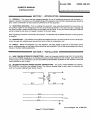
2-1.
WIRE
FEEDER-INTERFACE
CONNECTIONS
-
Insert
the
three-pole
twistlock
plug
from
the
combination
cord
into
the
POWER
receptacle
on
the
Interface
Control
and
rotate
clockwise
to
lock
in
place.
Insert
the
two-pole
twistlock
plug
from
the
combination
cord
into
the
CONTACTOR
CONTROL
receptacle
on
the
Interface
Control
and
rotate
clockwise
to
lock
in
place.
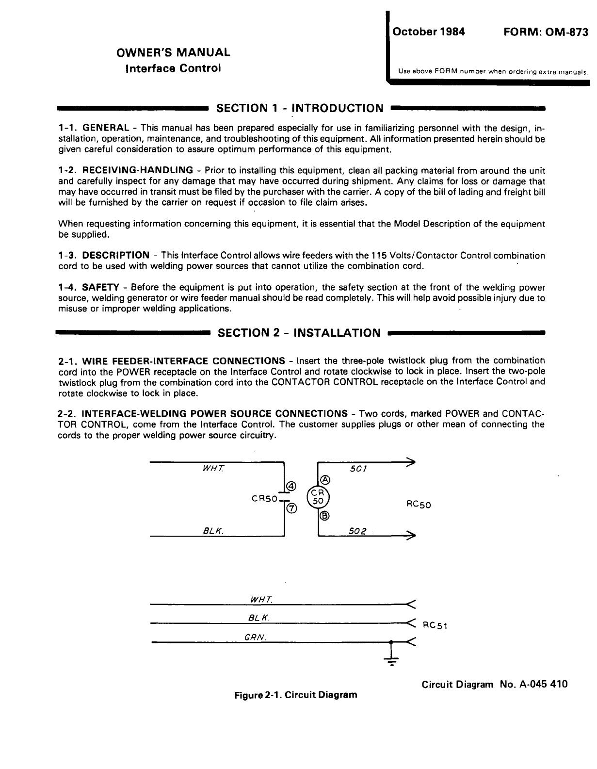
2-2.
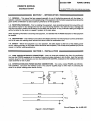
INTERFACE-WELDING
POWER
SOURCE
CONNECTIONS
-
Two
cords,
marked
POWER
and
CONTAC
TOR
CONTROL,
come
from
the
Interface
Control.
The
customer
supplies
plugs
or
other
mean
of
connecting
the
cords
to
the
proper
welding
power
source
circuitry.
WH~
I
I
501
CR5OT
L~)
RC50
'
BL/(.
________
502
14H
r
8L
K.
<
RC5~
CPN.
Circuit
Diagram
No.
A-045
410
Figure
2-1.
Circuit
Diagram
October
1984
FORM:
OM-873
Use
above
FORM
number
when
ordering
extra
manuals.

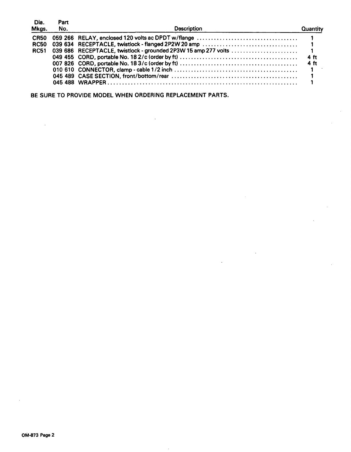
Dia.
Part
Mkgs.
No.
Description
Quantity
CR50
059
266
RELAY,
enclosed
120
voltsac
DPDTw/flange
1
RC5O
039 634
RECEPTACLE,
twistlock-flanged
2P2W20
amp
1
RC51
039
686
RECEPTACLE,
twistlock
-
grounded
2P3W
15
amp
277
volts
1
049 455
CORD,
portableNo.
182/c
(orderbyft)
4
ft
007
826
CORD,
portable
No.
183/c
(order
byft)
4
ft
010
610
CONNECTOR,
clamp
-
cable
1/2
inch
1
045
489
CASE
SECTION,
front/bottom/rear
1
045
488
WRAPPER
1
BE
SURE
TO
PROVIDE
MODEL
WHEN
ORDERING
REPLACEMENT
PARTS.
OM-873
Page
2

October
1984
FORM:
OM-87~
OWNERS
MANUAL
Interface
Control
Use
above
FORM
number
when
ordering
extra
manuals.
SECTION
1
-
INTRODUCTION
1-1.
GENERAL
-
This
manual
has
been
prepared
especially
for
use
in
familiarizing
personnel
with
the
design,
in
stallation,
operation,
maintenance,
and
troubleshooting
of
this
equipment.
All
information
presented
herein
should
be
given
careful
consideration
to
assure
optimum
performance
of
this
equipment.
1-2.
RECEIVING-HANDLING
-
Prior
to
installing
this
equipment,
clean
all
packing
material
from
around
the
unit
and
carefully
inspect
for
any
damage
that
may
have
occurred
during
shipment.
Any
claims
for
loss
or
damage
that
may
have
occurred
in
transit
must
be
filed
by
the
purchaser
with
the
carrier.
A
copy
of
the
bill
of
lading
and
freight
bill
will
be
furnished
by
the
carrier
on
request
if
occasion
to
file
claim
arises.
When
requesting
information
concerning
this
equipment,
it
is
essential
that
the
Model
Description
of
the
equipment
be
supplied.
1-3.
DESCRIPTION
-
This
Interface
Control
allows
wire
feeders
with
the
115
Volts/Contactor
Control
combination
cord
to
be
used
with
welding
power
sources
that
cannot
utilize
the
combination
cord.
1-4.
SAFETY
-
Before
the
equipment
is
put
into
operation,
the
safety
section
at
the
front
of
the
welding
power
source,
welding
generator
or
wire
feeder
manual
should
be
read
completely.
This
will
help
avoid
possible
injury
due
to
misuse
or
improper
welding
applications.
SECTION
2
-
INSTALLATION
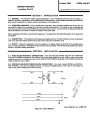
2-1.
WIRE
FEEDER-INTERFACE
CONNECTIONS
-
Insert
the
three-pole
twistlock
plug
from
the
combination
cord
into
the
POWER
receptacle
on
the
Interface
Control
and
rotate
clockwise
to
lock
in
place.
Insert
the
two-pole
twistlock
plug
from
the
combination
cord
into
the
CONTACTOR
CONTROL
receptacle
on
the
Interface
Control
and
rotate
clockwise
to
lock
in
place.
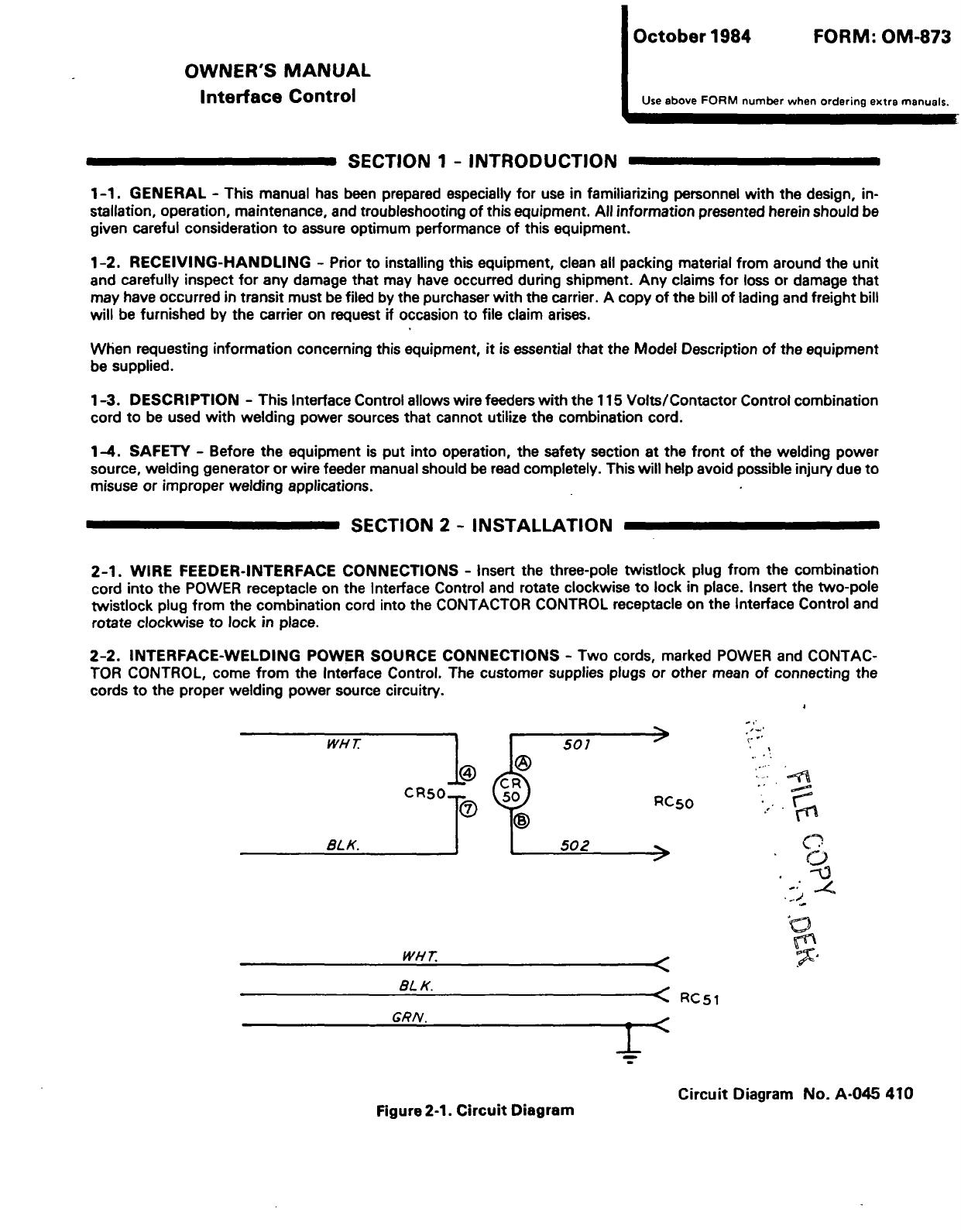
2-2.
INTERFACE-WELDING
POWER
SOURCE
CONNECTIONS
-
Two
cords,
marked
POWER
and
CONTAC
TOR
CONTROL,
come
from
the
Interface
Control.
The
customer
supplies
plugs
or
other
mean
of
connecting
the
cords
to
the
proper
welding
power
source
circuitry.
I
p
WI-fr
I
F
501
1fit~
cR5oT
~
RC5~
Ifi
BL/(.
_______
502
0
4~
0
I_-~
~
WH7
BLK.
~
RC5i
GRN.
I
Circuit
Diagram
No.
A-045
410
Figure
2-1.
Circuit
Diagram
Dia.
Part
Mkgs.
No.
Description
Quantity
CR50
059
266
RELAY,
enclosed
120
voltsac
DPDTw/flange
1
RC5O
039
634
RECEPTACLE,
twistlock
-
flanged
2P2W
20
amp
1
RC51
039
686
RECEPTACLE,
twistlock
-
grounded
2P3W
15
amp
277
volts
1
049 455
CORD,
portable
No.
182/c
(order
byft)
4
ft
007
826
CORD,
portable
No.
183/c
(order
byft)
4
ft
010
610
CONNECTOR,
clamp
-
cable
1/2
inch
1
045
489
CASE
SECTION,
front/bottom/rear
1
045
488
WRAPPER
1
BE
SURE TO
PROVIDE
MODEL
WHEN
ORDERING
REPLACEMENT
PARTS.
OM-873
Page
2
October
1984
FORM:
OM-873
OWNERS
MANUAL
Interface
Control
Use
above
FORM
number
when
ordering
extra
manuals.
SECTION
1
-
INTRODUCTION
1-1.
GENERAL
-
This
manual
has
been
prepared
especially
for
use
in
familiarizing
personnel
with
the
design,
in
stallation,
operation,
maintenance,
and
troubleshooting
of
this
equipment.
All
information
presented
herein
should
be
given
careful
consideration
to
assure
optimum
performance
of
this
equipment.
1-2.
RECEIVING-HANDLING
-
Prior
to
installing
this
equipment,
clean
all
packing
material
from
around
the
unit
and
carefully
inspect
for
any
damage
that
may
have
occurred
during
shipment.
Any
claims
for
loss
or
damage
that
may
have
occurred
in
transit
must
be
filed
by
the
purchaser
with
the
carrier.
A
copy
of
the
bill
of
lading
and
freight
bill
will
be
furnished
by
the
carrier
on
request
if
occasion
to
file
claim
arises.
When
requesting
information
concerning
this
equipment,
it
is
essential
that
the
Model
Description
of
the
equipment
be
supplied.
1-3.
DESCRIPTION
-
This
Interface
Control
allows
wire
feeders
with
the
115
Volts/Contactor
Control
combination
cord
to
be
used
with
welding
power
sources
that
cannot
utilize
the
combination
cord.
1-4.
SAFETY
-
Before
the
equipment
is
put
into
operation,
the
safety
section
at
the
front
of
the
welding
power
source,
welding
generator
or
wire
feeder
manual
should
be
read
completely.
This
will
help
avoid
possible
injury
due
to
misuse
or
improper
welding
applications.
SECTION
2
-
INSTALLATION
2-1.
WIRE
FEEDER-INTERFACE
CONNECTIONS
-
Insert
the
three-pole
twistlock
plug
from
the
combination
cord
into
the
POWER
receptacle
on
the
Interface
Control
and
rotate
clockwise
to
lock
in
place.
Insert
the
two-pole
twistlock
plug
from
the
combination
cord
into
the
CONTACTOR
CONTROL
receptacle
on
the
Interface
Control
and
rotate
clockwise
to
lock
in
place.
2-2.
INTERFACE-WELDING
POWER
SOURCE
CONNECTIONS
-
Two
cords,
marked
POWER
and
CONTAC
TOR
CONTROL,
come
from
the
Interface
Control.
The
customer
supplies
plugs
or
other
mean
of
connecting
the
cords
to
the
proper
welding
power
source
circuitry.
WH~
1
I
501
~
CR5OT
~
RC5O
BL/(
________
502
WH
T~
BL
K.
<
RC~~
GRN.
Circuit
Diagram
No.
A-045
410
Figure
2-1.
Circuit
Diagram
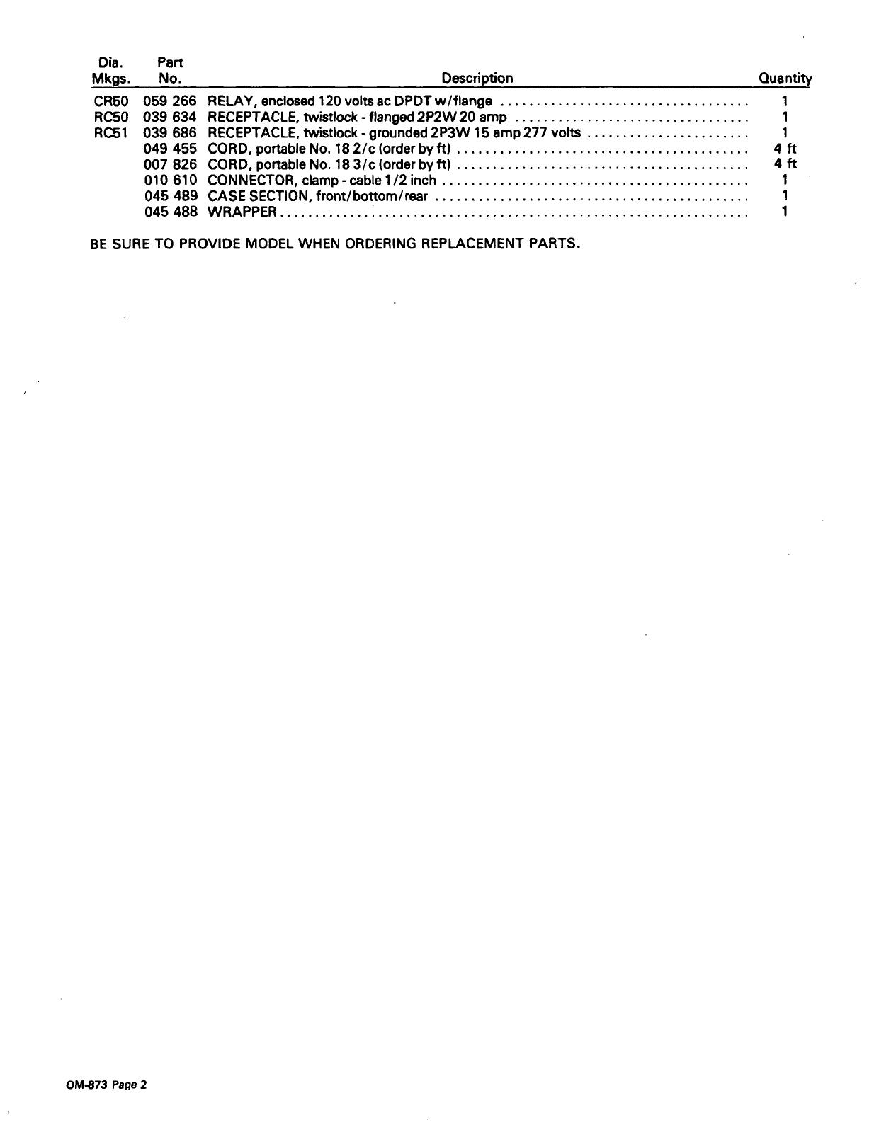
Dia.
Part
Mkgs.
No.
Description
Quantity
CR50
059
266
RELAY,
enclosed
120
voltsac
DPDTw/flange
1
RC5O
039
634
RECEPTACLE,
twistlock
-
flanged
2P2W20
amp
1
RC51
039
686
RECEPTACLE,
twistlock
-
grounded
2P3W
15
amp
277
volts
1
049
455
CORD,
portable
No.
182/c
(order
byft)
4
ft
007 826
CORD,
portable
No.
183/c
(order
by
ft)
4
ft
010
610
CONNECTOR,clamp-cablel/2
inch
1
045
489
CASE
SECTION,
front/bottom/rear
1
045
488
WRAPPER
1
BE
SURE
TO
PROVIDE
MODEL
WHEN
ORDERING
REPLACEMENT
PARTS.
OM-873
Page
2


 1
1
 2
2
 3
3
 4
4
 5
5
 6
6


Miller INTELLIMATE DW Owner's manual