
1
© Copyright 2013 Printed
Before You Start
Your Down Pressure Kit is exclusively designed for Land
Pride PD10, PD15, PD25, PD35, HD25 & HD35 Series
Post Hole Diggers. Please read these installation
instructions and your Operator’s Manual thoroughly
before beginning. Especially read information relating to
safety concerns. Also included in the Operator’s Manual
is important information on operation, adjustment,
troubleshooting, and maintenance for this attachment
(some manual sections do not apply to all accessories).
A separate Parts Manual for replacement parts can be
purchased from your dealer or available free of charge at
www.landpride.com. Have model and serial numbers
handy when placing an order.
Manual Part Numbers:
• PD10, PD15, PD25, PD35, HD25 & HD35 Series
Post Hole Digger Parts Manual . . . . . . . . . . . . . . . 317-048P
• PD10, PD15, PD25 & PD35 Series
Post Hole Digger Operator’s Manual . . . . . . . . . . . 317-048M
• HD25 & HD35 Series
Post Hole Digger Operator’s Manual . . . . . . . . . . . 317-076M
General Information
These assembly instructions apply to the optional Down
Pressure Kits listed below:
317-159A PD10 Down Pressure Kit
317-027A PD15 Down Pressure Kit
317-028A PD25/35 & HD25/35 Down Pressure Kit
The Down Pressure Kit allows for additional digging
force in hard soil conditions by use of a hydraulic cylinder
and cylinder plates. Down pressure created is between
300 and 500 lbs. depending on mounting configuration.
When you see this symbol, the subsequent
instructions and warnings are serious - follow
without exception. Your life and the lives of
others depend on it!
!
NOTE: Some tractor cabs may interfere with the
Down Pressure Kit. After installation, carefully raise
the post hole digger fully up with pressure cylinder
fully extended to check for cab interference.
IMPORTANT: Tractor hydraulics for operating the
down pressure cylinder must have float capabilities
otherwise the Post Hole Digger and Down Pressure
Kit can be damaged.
!
WARNING!
Before making any adjustments to your Post Hole Digger,
disengage PTO, shut off tractor and remove ignition key.
!
WARNING!
Be sure to relieve all hydraulic pressure before disconnecting any
lines or pipes between the Post Hole Digger and the tractor
hydraulic system.
!
DANGER!
Escaping hydraulic oil can have extremely high pressure. A
stream of high pressure oil may easily penetrate the skin as
with modern needle-less vaccination equipment - but with the
exception that hydraulic fluid may cause blood poisoning.
It is imperative that all hydraulic connections are tight and
that all lines and pipes are in good condition. Correct all
hydraulic leaks immediately. Use a piece of cardboard or
wood rather than hands when searching for hydraulic leaks.
If hydraulic fluid is injected into the skin, it must be treated
by a doctor within a few hours or gangrene may result.
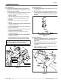
Down Pressure Kit
Figure 1
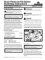
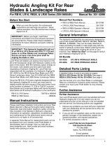
Refer to Figure 1:
The down pressure kit is ready for operating after it has
been properly installed on the Post Hole Digger (see
following pages for Assembly Instructions).
Normal digging operations are made with the tractor’s
hydraulic lever for the down pressure cylinder in neutral
position. When encountering hard soil, move control
lever in the proper direction to apply pressure and return
control lever to neutral position to continue normal digging
operations.
10133
Pressure Line
Return Line
to Sump
IMPORTANT: Relief valve (#1) is factory set at
1500 psi. and must not be changed. Exceeding this
pressure can damage the equipment.
PD10/15, PD25/35 & HD25/35 Series
Down Pressure Kit Option
Assembly Instructions
8/19/16
Manual No. 317-059M

2
Manual No. 317-059M 8/19/16
Land Pride
Assembly Instructions
Assembly Instructions
A detailed listing of parts for each accessory kit is
provided on page 6. Use the list that is for your Post Hole
Digger as a checklist to inventory parts received. Please
contact your local Land Pride dealer for any missing
hardware.
!
DANGER!
Escaping hydraulic oil can have extremely high pressure. A
stream of high pressure oil can easily penetrate the skin as
with modern needle-less vaccination equipment - but with the
exception that hydraulic fluid can cause blood poisoning.
It is imperative that all hydraulic connections are tight and
that all lines and pipes are in good condition. Correct all
hydraulic leaks immediately. Use a piece of cardboard or
wood rather than hands when searching for hydraulic leaks.
If hydraulic fluid is injected into the skin, it must be treated
by a doctor within a few hours or gangrene may result.
!
WARNING!
Before making any adjustments to your Post Hole Digger,
disengage PTO, shut tractor off and remove key.
PD10 and PD15 Down Pressure Assembly
1. Lower Post Hole Digger until auger point is resting on
the ground.
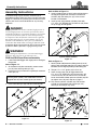
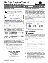
Refer to Figure 1-1:
2. At the boom and yoke connection, remove cotter
pin (#2) from existing clevis pin (#1).
3. Use new pin (#3) in one end as a guide pin to remove
clevis pin (#1).
4. Insert new clevis pin (#3) into this same location.
Boom/Yoke Pivot Pin Removal & Replacement
Figure 1-1
NOTE: PD15 boom bracket is supplied with three
mounting holes (shown) and PD10 Boom bracket is
supplied with only one mounting hole (not shown).
26821
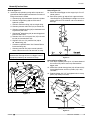
Refer to Refer to Figure 1-2:
5. Install cylinder plates (#1 & #2) with bushing tubes at
the top pointing towards each other and with flat
washers (#6) and cotter pins (#7) in the correct
location at the bottom.
6. Install spacer (#3) between cylinder plates with
1/2"-13 x 5 1/2" GR5 bolt (#4) and lock nut (#5). Draw
nut up snugly, do not tighten.
Cylinder Plate Installation
Figure 1-2
Refer to Figure 1-3:
7. Attach cylinder (#8) between cylinder plates (#1 & #2)
with pin (#8). Insert both cotter pins (#7) into pin (#8) and
bend one or more legs to prevent pin from falling out.
8. Torque 1/2" x 5 1/2" lg bolt (#5) to 76 ft. lbs.
9. Attach clamp plates (#3) to digger boom with
1/2"-13 x 2 1/4" GR5 bolts (#4) and lock nuts (#5).
Thread nuts only one or two full turns to allow for
easier attachment of down pressure cylinder (#9). Do
not tighten nuts (#5) until step 16 on page 3.
10. Fully retract hydraulic cylinder (#9) and connect
cylinder to clamp plates with cylinder pin (#11).
Secure pin with hairpin clip (#10).
Cylinder Installation
Figure 1-3
26822
26823

3
8/19/16 Manual No. 317-059M
Assembly Instructions
Land Pride
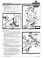
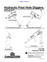
Refer to Figure 1-4:
11. Install hydraulic plumbing using teflon tape to seal
pipe threads. Do not tighten connections until after all
fittings have been installed.
a. Connect plug (#3) to rod end of hydraulic cylinder.
b. Connect straight fitting (#8) to clevis end of
hydraulic cylinder.
c. Connect shuttle tee fitting (#9) to straight fitting.
d. Connect pressure relief valve (#2) to shuttle tee.
e. Connect standard tee fitting (#5) to the bottom end
of pressure relief valve.
f. Connect 90
o
elbow fitting (#4) to remaining port of
pressure relief valve.
g. Connect 3/8" x 15 3/4" bypass line (#7) to shuttle
tee (#9) and standard tee (#5).
h. Connect 3/8" x 84 1/2" pressure line (#6) to
90
o
elbow fitting (#4).
i. Customer to provide return line. Connect Return
line to tee fitting (#5).
j. Connect pressure line (#6) to tractor hydraulic
outlet. Connect return line to reservoir or sump.
Down Pressure Cylinder Plumbing
Figure 1-4
IMPORTANT: Do not connect return line to tractor
remote outlet. Damage will occur to digger frame if
not properly hooked up to reservoir or sump.
26824
Return Line
to Sump
Pressure Line
Shuttle Tee
Nut Placement
Refer to Figure 1-5:
12. Raise Post Hole Digger so that auger tip is 6” to 12”
above ground.
13. Set tractor 3-point up-stop to limit auger maximum
raised height to 12”. Exceeding this height can cause
undue stress on PTO driveline and cause driveline
damage.
Setting Down Pressure Kit
Figure 1-5
Refer to Refer to Figure 1-6:
14. Push top of cylinder plates (#1 & # 2) forward toward
the tractor until plates have firmly contacted the
digger yoke.
15. Make sure cylinder clamp plates (#4) will move fairly
free on digger boom and that cylinder (#3) is fully
retracted.
16. Extend cylinder (#3) 1/2” and tighten bolts in clamp
plates (#4) evenly to 76 ft-lbs.
Setting Down Pressure Kit
Figure 1-6
14837
14838

4
Manual No. 317-059M 8/19/16
Land Pride
Assembly Instructions
PD25/35 & HD25/35 Down Pressure Assembly
Refer to Figure 2-1:
1. Lower Post Hole Digger unit until auger point is
resting on the ground.
2. Remove cotter pins (#2) holding boom pivot pin (#3)
in place.
3. Partially remove pivot pin to the right side until spacer
(#1) can be removed from the left side.
Boom/Yoke Pivot Pin & spacer Removal
Figure 2-1
Refer to Figure 2-2:
4. Insert spacer (#1) into hole in down pressure cylinder
plate (#5) located on the left side of Post Hole Digger.
5. Place left side cylinder plate with spacer back into pin
position. Make sure bushing tube at the top is
pointing inward as shown.
6. Push pin (#3) in until pin projects through spacer (#1)
and out through yoke mounting bracket on the left
side.
7. Repeat steps 3 to 6 for the right side spacer and
down pressure cylinder plate (#4).
8. Install spacer (#6) between cylinder plates (#4 & 5).
9. Insert bolt (#7) through cylinder plates (#4 & 5) and
spacer (#6). Draw nut up snugly, do not tighten.
Refer to Figure 2-3:
10. Attach cylinder (#9) between cylinder plates (#1 & #2)
with pin (#8). Insert both cotter pins (#7) into pin (#8) and
bend one or more legs to prevent pin from falling out.
11. Torque 1/2" x 5 1/2" lg bolt (#5) to 76 ft. lbs.
12. Attach clamp plates (#3) to digger boom with
1/2"-13 x 2 1/4" GR5 bolts (#4) and lock nuts (#6).
Thread nuts only one or two full turns to allow for
easier attachment of down pressure cylinder (#9). Do
not tighten nuts (#6) until step 19 on page 5.
13. Fully retract hydraulic cylinder (#9) and connect
cylinder to clamp plates with cylinder pin (#11).
Secure pin with hairpin clip (#10).
26826
Left Side
Right Side
Cylinder Plate Installation
Figure 2-2
Cylinder Clamp Plate Installation
Figure 2-3
26827
Bushing Tubes
Yoke Mounting
Bracket
26828

5
8/19/16 Manual No. 317-059M
Assembly Instructions
Land Pride
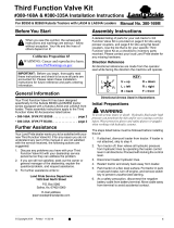
Refer to Figure 2-4:
14. Install hydraulic plumbing using teflon tape to seal
pipe threads. Do not tighten connections until after all
fittings have been installed.
a. Connect plug (#3) to rod end of hydraulic cylinder.
b. Connect straight fitting (#8) to clevis end of
hydraulic cylinder.
c. Connect shuttle tee fitting (#9) to straight fitting.
d. Remove 1/4" MNPT plug from bottom of relief
valve (#2).
e. Connect pressure relief valve (#2) to shuttle
tee (#9).
f. Connect standard tee fitting (#5) to the bottom end
of pressure relief valve.
g. Connect 90
o
elbow fitting (#4) to remaining port of
pressure relief valve.
h. Connect 3/8" x 15 3/4" bypass line (#7) to shuttle
tee (#9) and standard tee (#5).
i. Connect 3/8" x 84 1/2" pressure line (#6) to
90
o
elbow fitting (#4).
j. Customer to provide return line. Connect Return
line to tee fitting (#5).
k. Connect pressure line (#6) to tractor hydraulic
outlet. Connect return line to reservoir or sump.
Down Pressure Cylinder Plumbing
Figure 2-4
IMPORTANT: Do not connect return line to tractor
remote outlet. Damage will occur to digger frame if
not properly hooked up to reservoir or sump.
26829
Return Line
to Sump
Pressure Line
Shuttle Tee
Nut Placement
Refer to Figure 2-5:
15. Raise Post Hole Digger so that auger tip is 6” to 12”
above ground.
16. Set tractor 3-point up-stop to limit auger maximum
raised height to 12”. Exceeding this height can cause
undue stress on PTO driveline and cause driveline
damage.
Setting Down Pressure Kit
Figure 2-5
Refer to Figure 2-6:
17. Push top of cylinder plates (#1 & # 2) forward toward
the tractor until plates have firmly contacted the
digger yoke.
18. Make sure cylinder clamp plates (#4) will move fairly
free on digger boom and that cylinder (#3) is fully
retracted.
19. Extend cylinder (#3) 1/2” and tighten bolts in clamp
plates (#4) evenly to 76 ft-lbs.
Set Down Pressure Kit
Figure 2-6
14837
14838

Land Pride
Listing of Parts
Manual No. 317-059M 8/19/16
6
Qty. Part No. Part Description
1 317-022H PD25/35 DOWN PRESS CYL PLT RH
1 317-023H PD25/35 DOWN PRESS CYL PLT LH
1 317-026D TUBE RD 1 X .219 WL X 3 1/2
2 317-048D PD25/35 BOOM CLAMP PLATE
4 802-038C HHCS 1/2-13X2 1/4 GR5
1 802-046C HHCS 1/2-13X5 1/2 GR5
5 803-019C NUT LOCK 1/2-13 PLT
2 805-017C PIN COTTER 3/16 X 1 3/4 PLT
1 805-229C PIN 1 OD - 4 7/8 USEABLE
1 810-005C CYL 2X8X1.12 ROD SINGLE ACTING
1 810-297C VALVE RELIEF W/TAMP PROOF CART
1 811-019C PLUG 3/8MNPT BREATHER
1 811-063C EL 3/4MJIC 3/4MORB
1 811-077C TE 3/4MORB 3/4MJIC 3/4MJIC
1 811-258C HH3/8R2 084 1/2MNPT 3/4FJIC
1 811-949C HH3/8R2 015 3/4FJIC
1 838-094C DECAL WARNING HYD PRESS LONG
1 841-323C AD 3/4FJIC 3/8MNPT
1 891-357C TE 3/4MORB 3/4MJIC (2) SHUTTLE
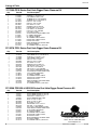
317-159A PD10 Series Post Hole Digger Down Pressure Kit
317-027A PD15 Series Post Hole Digger Down Pressure Kit
Qty. Part No. Part Description
317-028A PD25/35 & HD25/35 Series Post Hole Digger Down Pressure Kit
1 317-020H PD15 DOWN PR CYL PLT WELD RH
1 317-021H PD15 DOWN PR CYL PLT WELD LH
1 317-026D TUBE RD 1 X .219 WL X 3 1/2
2 317-046D PD15 BOOM CLAMP PLATE
4 802-038C HHCS 1/2-13X2 1/4 GR5
1 802-046C HHCS 1/2-13X5 1/2 GR5
5 803-019C NUT LOCK 1/2-13 PLT
2 804-025C WASHER FLAT 3/4 SAE PLT
4 805-017C PIN COTTER 3/16 X 1 3/4 PLT
1 805-229C PIN 1 OD - 4 7/8 USEABLE
1 805-230C PIN 3/4 OD - 4 13/32 USEABLE
1 810-005C CYL 2X8X1.12 ROD SINGLE ACTING
1 810-297C VALVE RELIEF W/TAMP PROOF CART
1 811-019C PLUG 3/8MNPT BREATHER
1 811-063C EL 3/4MJIC 3/4MORB
1 811-077C TE 3/4MORB 3/4MJIC 3/4MJIC
1 811-258C HH3/8R2 084 1/2MNPT 3/4FJIC
1 811-949C HH3/8R2 015 3/4FJIC
1 838-094C DECAL WARNING HYD PRESS LONG
1 841-323C AD 3/4FJIC 3/8MNPT
1 891-357C TE 3/4MORB 3/4MJIC (2) SHUTTLE
Qty. Part No. Part Description
1 317-026D TUBE RD 1 X .219 WL X 3 1/2
2 317-046D PD15 BOOM CLAMP PLATE
1 317-157H 10 DOWN PR CYL PLT WELD RH
1 317-158H 10 DOWN PR CYL PLT WELD LH
4 802-038C HHCS 1/2-13X2 1/4 GR5
1 802-046C HHCS 1/2-13X5 1/2 GR5
5 803-019C NUT LOCK 1/2-13 PLT
2 804-025C WASHER FLAT 3/4 SAE PLT
4 805-017C PIN COTTER 3/16 X 1 3/4 PLT
1 805-229C PIN 1 OD X 4 7/8 USEABLE
1 805-230C PIN 3/4 X 4 13/32 USEABLE
1 810-005C CYL 2X8X1.12 ROD
1 810-297C VALVE RELIEF W/TAMP PROOF CART
1 811-019C PL 3/8MNPT BREATHER
1 811-063C EL 3/4MJIC 3/4MORB
1 811-077C TE 3/4MORB 3/4MJIC 3/4MJIC
1 811-258C HH3/8R2 084 1/2MNPT 3/4FJIC
1 811-949C HH3/8R2 015 3/4FJIC
1 838-094C DECAL WARNING HYD PRESS LONG
1 841-323C AD 3/4FJIC 3/8MNPT
1 891-357C TE 3/4MORB 3/4MJIC (2) SHUTTLE
Corporate Office: P.O. Box 5060
Salina, Kansas 67402-5060 USA
www.landpride.com
-
 1
1
-
 2
2
-
 3
3
-
 4
4
-
 5
5
-
 6
6


Ask a question and I''ll find the answer in the document
Finding information in a document is now easier with AI
Related papers
-
Land Pride PD10 Series User manual
-
-
 Land Pride HD35 User manual
-
 Land Pride PD25 Series User manual
-
 Land Pride LR26 User manual
-
 Land Pride 3rd User manual
-
 Land Pride HD35 User manual
-
 Land Pride CB10 Series User manual
-
-
 Land Pride RCCM5615 User manual


Other documents
-
 Nortrac 3-Pt. PTO Post Hole Digger Owner's manual
-
Behlen Country PHD Owner's manual
-
Woods TPD35 User manual
-
 Sansen FAPT1860 User manual
-
Bush Hog Posthole Digger Owner's manual
-
-
-
FLEXIHIRE 1-Man Post Hole Digger Operating instructions
-
General 210 User manual
-
 Braber Equipment BE-PHDG User manual


