Salsbury Industries 71162GY-A Installation guide

Category
Cable clamps
Type
Installation guide
Vented Lockers – 71000 Series
Single Tier Installation Instructions
Thank you for selecting Salsbury’s vented single tier lockers. We are confident that the quality and construction of the lockers will prove to be a good
investment. These instructions are intended to assist you in assembling the lockers. The lockers should then be placed in the installed location and
anchored to the floor, wall, or to both. Individual job conditions will dictate the type of anchor fasteners.
Preliminary Note
Please read the complete assembly instructions before attempting to
assemble the lockers. Check the materials to be sure that they are
correct for the job and that there is no damage.
Be careful to use the correct hardware. Use screw no. 1 all around
with screw heads out, except where noted. Lockers should be
assembled in groups as indicated in the order of the drawings.
The essential tools required for assembling the lockers are a 5/16”
nut driver and 2 small nail punches or drift pins for hole alignment.
The lockers should be assembled on a flat level surface and installed
in position, anchoring to the floor or wall, as required.
See the illustration to the right to identify the locker parts. Note that
the sloping hood, front base, end base, and name plate are optional
items and their assembly is covered by a separate installation
instruction. Also note that the coat rod is included with the 18” deep
models only.
Assembly
1. Fasten a top, bottom, and side to a back. The top and bottom are
identical parts and should have the flanges down. Insert a rear leg
and fasten. See Illustration 1.
2. Fasten a shelf in position under the top. See Illustration 2.
For a one-wide locker, skip to Step 4.
Illustration 1
Parts Identification
Illustration 2
SALSBURY INDUSTRIES
1010 East 62
nd
Street, Los Angeles, CA 90001-1598
Phone: 1-800-562-5377 Int’l Phone: 323-846-6700
Fax: 1-800-562-5399 Int’l Fax: 323-846-6800
Installation instructions are provided as general guidelines. It is advised that a professional installer be consulted. Salsbury Industries assumes no product assembly or installation liability.
Copyright © 2010 Salsbury Industries. All rights reserved. (Rev. 06, 8/4/2010)
Vented Lockers – 71000 Series
Single Tier Installation Instructions
Assembly (continued)
3. Position additional sides, backs, tops, bottoms, and shelves and
fasten in place. See Illustration 3.
4. Add a last side (flange in) and the other leg. See Illustration 4.
5. Attach the door and frame assemblies, ensuring that the front
edges of the sides are inside a frame assembly flange and not
between frames. See Illustration 5.
Illustration 3
Illustration 4
6. Fasten the last door and frame assembly into place, ensuring that
they are all fastened correctly. See Illustration 6.
7. Finally, install coat hooks below the top and lock hole fillers into
the doors. If there are built-in locks, install locks instead of lock hole
fillers.
Illustration 5
Illustration 6
Side Panel Hole Locations for Shelves
SALSBURY INDUSTRIES
1010 East 62
nd
Street, Los Angeles, CA 90001-1598
Phone: 1-800-562-5377 Int’l Phone: 323-846-6700
Fax: 1-800-562-5399 Int’l Fax: 323-846-6800
Installation instructions are provided as general guidelines. It is advised that a professional installer be consulted. Salsbury Industries assumes no product assembly or installation liability.
Copyright © 2010 Salsbury Industries. All rights reserved. (Rev. 06, 8/4/2010)
Vented Lockers – 71000 Series
Installation Instructions - Options
Thank you for selecting Salsbury’s vented single tier lockers. We are confident that the quality and construction of the lockers will prove to be a good
investment. These instructions are intended to assist you in assembling option items into the locker. The name plates, front bases, end bases, and
sloping hoods are each separate option items and may or may not be included in your order.
Name Plates
The name plates are installed with #4 slotless screws and nuts.
Sloping Hoods
The sloping hoods are assembled and installed on the locker units
with #10 x 3/8” slotless screws and nuts. The side plates should be
installed inside the flanges of the sloping hood. Only 1 side panel
should be assembled between adjacent sloping hoods.
SALSBURY INDUSTRIES
1010 East 62
nd
Street, Los Angeles, CA 90001-1598
Phone: 1-800-562-5377 Int’l Phone: 323-846-6700
Fax: 1-800-562-5399 Int’l Fax: 323-846-6800
Front Bases and End Bases
The front bases are simply snapped into position between the two
legs in the front of the locker unit. No fasteners are required due to
the dimples on the front base flanges.
The end bases are installed and fastened with 2 screws and nuts
such that the end base front edge is inserted inside the locker front
leg with the end base rear flanges wrapped around the outside of the
locker rear leg.
Installation instructions are provided as general guidelines. It is advised that a professional installer be consulted. Salsbury Industries assumes no product assembly or installation liability.
Copyright © 2010 Salsbury Industries. All rights reserved. (Rev. 06, 8/4/2010)
Vented Lockers – Locker Benches
Assembly & Installation Instructions
Thank you for selecting Salsbury’s 77770 series locker aluminum benches. We are confident that the quality and construction of this product will
provide years of maintenance free use.
Preliminary Notes
There are two basic steps to assembly and installation:
1. The bench pedestals must be assembled to the bench top.
2. The bench assembly must be bolted to the floor.
Failure to bolt the bench assembly to the floor could result in
injury to persons sitting on the bench.
Since various types of floors require different types of fasteners, floor
installation hardware is not provided. The hardware provided is for
fastening the bench pedestals to the bench top.
Two bench pedestals are provided for each bench top. Each bench
pedestal should be installed 6” from the end of each side of the
bench top.
Assembly
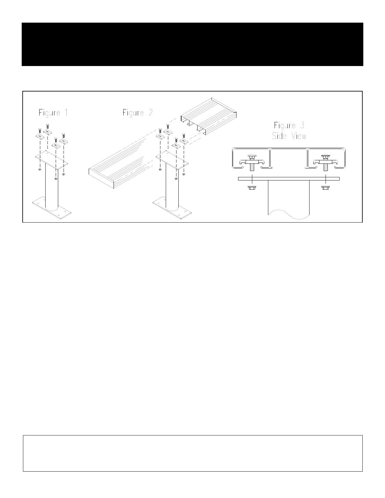
Install one of the 5/16” by 1-1/4” long carriage bolts through a
straddle clamp and loosely attach it to the bench pedestal with one of
the 5/16” serrated flange nuts as shown in Figure 1. The straddle
clamps should be installed on the end of the bench pedestal with the
smaller plate. Do this with the remaining three straddle clamps in the
first bench pedestal and repeat for the four clamps in the second
bench pedestal.
Set the bench top on a flat surface upside down. Rotate each of the
straddle clamps on a bench pedestal aligned such that they can be
inserted into the bottom of the bench top as shown in Figure 2.
Rotate them each 90 degrees so that they straddle and grip the
inside lips of the bench top when the nuts are tightened as shown in
Figure 3. Ensure that the straddle clamps are aligned with the lips.
Also ensure that the square section of the carriage bolts are inside
the square slots in the straddle clamps. Tighten the nuts until the
clamps are not quite gripping the lips inside the bench top. Slide the
bench pedestal to a position 6” from one end of the bench top.
Adjust the position of the bench pedestal so that it is centered
crosswise under the bench top and tighten the nuts securely.
Repeat for the other bench pedestal, installing it 6” from the other
end of the bench top.
Complete the installation by fastening the assembled bench to
the floor.
SALSBURY INDUSTRIES
1010 East 62
nd
Street, Los Angeles, CA 90001-1598
Phone: 1-800-562-5377 Int’l Phone: 323-846-6700
Fax: 1-800-562-5399 Int’l Fax: 323-846-6800
Installation instructions are provided as general guidelines. It is advised that a professional installer be consulted. Salsbury Industries assumes no product assembly or installation liability.
Copyright © 2008 Salsbury Industries. All rights reserved. (Rev. 02, 1/29/2008)
  • Page 1 1
  • Page 2 2
  • Page 3 3
  • Page 4 4

Salsbury Industries 71162GY-A Installation guide

Category
Cable clamps
Type
Installation guide

Ask a question and I''ll find the answer in the document

Finding information in a document is now easier with AI