
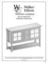
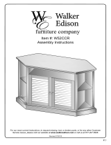
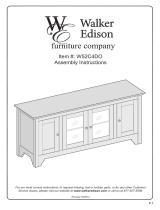
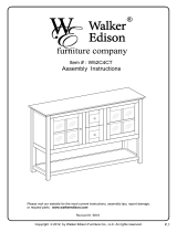
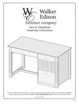
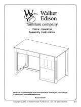
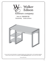
Item #: W52C2DW
Assembly Instructions
For our most current instructions, to request missing, lost or broken parts, or for any other Customer
Service issues, please visit our website at www.walkeredison.com or call us at 877-207-5906.
Revised 11/2010

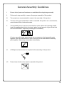
General Assembly Guidelines
I. Ensure that all parts and hardware are available before beginning assembly.
II. Follow each step carefully to ensure the proper assembly of this product.
III. Two people are recommended for ease in the assembly of this product.
IV. The four main types of hardware used to assemble this product are: wood dowels,
cam bolts and locks, bolts and screws.
V. The provided glue is to secure wood dowels in place. When first inserting dowels,
locate the appropriate hole for the dowel, place a small amount of glue in the hole
and insert the dowel. Wipe away excess glue immediately.
In future assembly steps when dowels are necessary to attach assembly parts
together, place a small amount of glue on the end of the dowel before attaching
parts together. Wipe away excess glue immediately.
VI. A Phillips head screwdriver is required for the assembly of this product.
VII. Power tools should not be used to assemble this product.
P.2

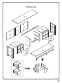
Parts List

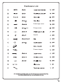
Hardware List
Extra-large screw
Flange screw
Handle
Drawer stopper

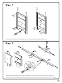
Insert large dowels (A) into side panels (1,2). Screw cam bolts (C) into side panels (1,2).
Insert small dowels (B) into panels (7,8) and slats (3,9). Insert large dowels (A) into slat (3). Attach door
stoppers (L) to slat (3) using large screws (N). Attach drawer stopper (M) to slat (9) using medium screw (P).
L
L

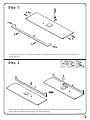
Attach slat (6) to bottom panel (4) using cam bolt and dowels as guides. Insert cam lock (D) into slat (6) and
tighten with a screwdriver. Screw leg (5) into bottom panel (4).
Insert large dowels (A) into slat (6). Insert small dowels (B) into bottom panel (4). Screw cam bolt (C) into
bottom panel (4).

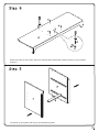
Join panels (7,8) together with slat (9). Use dowels as guides.
Screw cam bolts (C) into bottom panel (4). Attach drawer stopper (M) to bottom panel (4) using medium
screw (P).

Attach slat (3) to the assembly from the previous step using dowels as a guide.
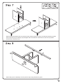
Attach the panel assembly from the previous step to bottom panel (4) using cam bolts and dowels as guides.
Insert cam locks (D) into panels (7,8) and tighten with a screwdriver. Note that two cam locks (D) will be
inserted into each panel (7,8).

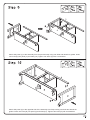
Attach side panel (2) to the opposite side of the assembly from Step 8 using cam bolts and dowels as
guides. Insert cam locks (D) into panel (4) and slats (3,6). Tighten cam locks (D) with a screwdriver.
Attach side panel (1) to the assembly from the previous step using cam bolts and dowels as guides. Insert
cam locks (D) into panel (4) and slats (3,6). Tighten cam locks (D) with a screwdriver.
4
6
3

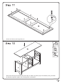
Insert cam locks (D) into the assembly from Step 10. Attach top panel (10) to the assembly using cam bolts
and dowels as guides. Tighten cam locks (D) with a screwdriver.
Screw cam bolts (C) into top panel (10).

Attach back panels (11,12) to the assembly from the previous step using flange screws (F). Note that back
panels (12) will overlap back panel (11).
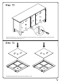
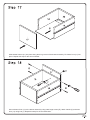
Carefully place glass panes (16) into door frames (14,15).

Attach drawer sides (18,19) to drawer back (20) using extra-large screws (E). Note that the thin grooves at
the base of each drawer piece will align along the inside of the drawer assembly. Repeat this step for the
second drawer.
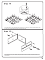
Secure glass panes (16) by attaching metal washers (K) to door frames (14,15) with small screws (Q). Note
that the curve of metal washers (K) will arc into glass panes (16).
16
16

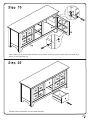
Secure drawer front (17) to the drawer assembly using extra-large screws (E). Attach handle (H) to drawer
front (17) using bolt (J). Repeat this step for the second drawer.
Slide drawer bottom (21) into place along the thin grooves of the drawer assembly. Fit drawer front (17) into
place. Repeat this step for the second drawer.

Carefully slide both drawers into the stand assembly.
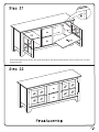
Attach doors (14,15) to the stand assembly using medium screws (P) at the hinges. Attach handles (H) to
doors (14,15) using bolts (J).

Insert shelf support pins (G) into the stand assembly at the desired shelf heights. Place shelves (13) on shelf
support pins (G).
-
 1
1
-
 2
2
-
 3
3
-
 4
4
-
 5
5
-
 6
6
-
 7
7
-
 8
8
-
 9
9
-
 10
10
-
 11
11
-
 12
12
-
 13
13
-
 14
14
-
 15
15


Walker W52C2DWWB User manual
- Type
- User manual
- This manual is also suitable for
Ask a question and I''ll find the answer in the document
Finding information in a document is now easier with AI
Related papers
-
 Walker Edison Furniture Company HD52C4TRB User manual
-
Walker WQ42BC1BL User manual
-
-
-
-
 Walker Edison Furniture Company W52CCRWH User manual
-
 Walker Edison Furniture Company WQ44CMPTB User manual
-
-
 Walker Edison Furniture Company HD44CCRAG User manual
-
Walker Edison Furniture Company HD70C25SDBL User manual


Other documents
-
Walker Edison Furniture Company WQ44CFD Operating instructions
-
ROOMS TO GO MAG-14-Natural/Black-CT Assembly Instructions
-
 Walker Edison Furniture Company W52C4DOBL Operating instructions
-
 Walker Edison Furniture Company HD8711 Operating instructions
-
 Walker Edison Furniture Company HD52C4DOAGY Operating instructions
-
 Walker Edison Furniture Company AZ42STCGW Installation guide
-
 Krosswood Doors PC-WS-W3624 Operating instructions
-
 Walker Edison Furniture Company DW48D30-DHWH Operating instructions
-
 Walker Edison Furniture Company HDW48D30GY Installation guide
-
 Walker Edison Furniture Company HD48UBC30AG Operating instructions


