Roland JD-XA Owner's manual

Category
Sequencer
Type
Owner's manual
Owners Manual
取扱説明書
Bedienungsanleitung
Mode d’emploi
Manuale dell'utente
Manual del usuario
Manual do Proprietário
Gebruikershandleiding
JD-XA Structure Diagram
Click
Master
Mute
Write the Program/
Backup the Program/
Export the SMF
Default MIDI Channel 16
Default MIDI Channel 14
Default MIDI Channel 15
Default MIDI Channel 13
Analog Part 04
Analog Part 03
Analog Part 02
Analog Part 01
Cross Mod
Ring Mod
Drive Analog Filter
LPF1
LPF2
LPF3 / HPF / BPF
HPF
AMP
LEVEL
LEVEL
AUX
White Noise
Pink Noise
Digital Part
Mic
OSC Sync
LEVEL
Analog OSC 2
Analog OSC 1
Default MIDI Channel 4
Default MIDI Channel 2
Default MIDI Channel 3
Default MIDI Channel 1
Digital Part 04
Digital Part 03
Digital Part 02
Digital Part 01
Default MIDI Channel 8
Default MIDI Channel 6
Default MIDI Channel 7
Default MIDI Channel 5
MFXRing Mod Part EQ
Digital OSC
Digital OSC
Digital Filter AMP
Digital Filter AMP
Digital Filter AMP
SuperNATURAL Synth Tone
Pitch ENV 1/2/3
LFO 1/2/3
ModLFO 1/2/3
Filter ENV 1/2/3
LFO 1/2/3
ModLFO 1/2/3
AMP ENV 1/2/3
LFO 1/2/3
ModLFO 1/2/3
Select the AUX’s
Digital Part source.
Default MIDI Channel 12
Default MIDI Channel 10
Default MIDI Channel 11
Default MIDI Channel 9
MIDI Control Part 08
MIDI Control Part 07
MIDI Control Part 06
MIDI Control Part 05
MIDI Control Part 04
MIDI Control Part 03
MIDI Control Part 02
MIDI Control Part 01
MFX Part EQ
Vocoder
Send Sw
Keyboard/
Arpeggio/
Controller
Sequencer
MIDI ch 1–16
One MIDI ch assignable
Phones Out
Click Out
Main Out
USB Audio
USB MIDI
CV Out 1/2
USB
MEMORY
MIDI Out
Master
Volume
Master
Mute
Analog Dry
Out
Program
Track 16
Track 15
Track 14
Track 13
Track 12
Track 11
Track 10
Track 9
Track 8
Track 7
Track 4
Track 3
Track 6
Track 5
Track 2
Track 1
MIDI Ch 16
MIDI Ch 15
MIDI Ch 14
MIDI Ch 13
MIDI Ch 12
MIDI Ch 11
MIDI Ch 10
MIDI Ch 9
MIDI Ch 8
MIDI Ch 7
MIDI Ch 4
MIDI Ch 3
MIDI Ch 6
MIDI Ch 5
MIDI Ch 2
MIDI Ch 1
Mod Source Sw
Partial 01
Partial 02
Partial 03
MIDI In
Select the Program/
Restore
the Program/
Import the SMF/
Copy the Part, Partial, Pattern and SuperNATURAL Synth Tone
Mic Input NS
Mic Modulation
Vocoder
Bypass
To AUX Mic
Mic Reverb
Delay
Vocoder
Reverb TFX 1 TFX 2
ON
OFF
Master EQ
Digital OSC
AMP ENV
LFO 1/2
Mod LFO
Pitch ENV 1/2
LFO 1/2
Mod LFO
Filter ENV
LFO 1/2
Mod LFO
Owners Manual
(this document)
Read this rst. It explains the basic things you need to know in order to use the JD-XA.
PDF Manual
(download from the Web)
5
Parameter Guide
(English)
This explains all parameters of the JD-XA.
5
MIDI Implementation
(English)
This is detailed information about MIDI messages.
To obtain the PDF manual
1.
Enter the following URL in your computer.
http://www.roland.com/manuals/
I
2.
Choose JD-XA as the product name.
Before using this unit, carefully read “USING THE UNIT SAFELY” and “IMPORTANT NOTES” (leaet “USING THE UNIT SAFELY” and Owners Manual (p. 18)). After reading, keep the document(s) including
those sections where it will be available for immediate reference.
© 2015 Roland Corporation
Contents
Panel Descriptions
.................................... 2
Top Panel
........................................... 2
Rear Panel
........................................... 3
Introduction
.......................................... 4
Turning On/O the Power
............................... 4
Selecting a Sound (Program)
............................. 4
Selecting a Part
....................................... 4
Editing a Sound (Program)
............................. 5
Editing an Analog Part
................................. 5
Editing a Digital Part
................................... 6
Editing the Eects
..................................... 6
Initializing a Sound (Init)
................................ 7
Copying a Sound or Pattern (Copy)
........................ 7
Saving a Program (Write)
............................... 7
Using Favorite Sounds (Programs) (Favorite)
................. 7
Recording (Pattern Sequencer)
......................... 8
Realtime Recording (Real Time REC)
....................... 8
Step Recording (Step REC)
.............................. 8
Step Recording 2 (Step REC 2)
............................ 8
Playing Patterns
...................................... 9
Erasing an Entire Pattern (Pattern Erase)
.................... 9
Pattern Utility
........................................ 9
Saving a Pattern (Write)
................................. 9
Playing an Arpeggio
................................... 9
Selecting an Arpeggio Template
.......................... 9
Editing an Arpeggio Pattern
............................. 9
Saving an Arpeggio (Write)
.............................. 9
Using the Microphone
................................. 10
Adjusting the Input Level
............................... 10
Using the Vocoder
..................................... 10
Using a Microphone to Apply Modulation
.................. 10
Outputting the Mic’s Vocal Input
.......................... 10
Controlling Your Performance
.......................... 10
Changing the Pitch/Applying Vibrato
(Pitch Bend/Modulation Lever)
. . . . . . . . . . . . . . . . . . . . . . . . . . . 10
Using an Assigned Function to Modify the Sound (WHEEL 1/2)
.. 10
Using External Pedals (HOLD/CTRL 1/CTRL 2)
................ 10
Connecting External Devices
........................... 11
Using the JD-XA as a MIDI Controller
...................... 11
Connecting an Analog Synthesizer via the CV/GATE Output
..... 11
Connecting a Computer via USB
.......................... 11
Overall Settings for the JD-XA
.......................... 12
Accessing the Menu Screens
............................. 12
Making System Settings (SYSTEM)
........................ 12
Saving the System Settings
.............................. 14
Convenient Functions (UTILITY)
.......................... 14
Formatting a USB Flash Drive (USB MEM FORMAT)
............ 14
Restoring Backup Data from a USB Flash Drive
............... 15
Returning to the Factory Settings (FACTORY RESET)
........... 15
Making the Power Automatically Turn O After a Time (Auto O )
15
Customizing the Knob and Slider Illumination (LED CUSTOMIZE)
. 15
List of Shortcut Keys
................................... 16
Error Messages
........................................ 17
Main Specications
.................................... 17
USING THE UNIT SAFELY
............................... 18
IMPORTANT NOTES
.................................... 18
Placing the JD-XA on a Stand
............................ 18
Owners Manual
2
Panel Descriptions
Top Panel
1
2
3
4
5 6 7
3
1
Common section
Here you can make the following settings for the JD-XA.
Controller Explanation
MASTER [Mute] button
Mutes the sound from the OUTPUT L/MONO and R jacks and the
ANALOG DRY jack.
MASTER [Volume] knob
Adjusts the volume of the sound that’s output from the OUTPUT L/
MONO and R jacks and the PHONES jack.
Display
Shows various information for the operation.
* The explanations in this manual include illustrations that depict
what should typically be shown by the display. Note, however, that
your unit may incorporate a newer, enhanced version of the system
(e.g., includes newer sounds), so what you actually see in the display
may not always match what appears in the manual.
Cursor [
K
] [
J
] buttons Move the cursor left/right.
[-] [+] buttons Change the value at the cursor position.
[MIDI CTRL] button
Lets you use the JD-XAs controllers to control an external MIDI device.
&
“Using the JD-XA as a MIDI Controller” (p. 11)
[Menu] button
Accesses the Menu screen.
&
Accessing the Menu Screens (p. 12)
[Write] button
Saves the edited data.
&
“Saving a Program (Write)” (p. 7)
[Shift] button
When used in conjunction with other buttons or knobs, lets you view
parameters or edit dierent parameters.
&
“List of Shortcut Keys” (p. 16)
[Exit] button
Returns you to the previous screen.
In some screens, this cancels the operation currently being executed.
When used in conjunction with a knob, lets you view the current
parameter without changing its value.
[Enter] (Manual) button
Press this to conrm a value or execute an operation.
If you press this button while holding down the [Shift] button, the
positions of all knobs and sliders are applied to the sound you’re
editing (Manual).
PROGRAM No. display
Displays the currently selected program number (
A01.
P16.
).
If the program or pattern has been edited, the decimal point is lit.
[Program Select] (Init)
button
Lets you use the [01]–[16] buttons to select programs.
If you hold down the [Shift] button and press this button, the Init
Menu screen appears.
&
“Initializing a Sound (Init)” (p. 7)
[Bank] (Copy) button
Press this button to make it blink, and then use the [01] (A)–[16]
(P) buttons to select the program bank. When you’ve selected the
program bank, the button goes dark, returning to its previous state.
If you hold down the [Shift] button and press this button, the Copy
Menu screen appears.
&
“Copying a Sound or Pattern (Copy)” (p. 7)
[USB Memory] button Lets you use programs that are stored on a USB ash drive.
[Favorite] button
Lets you register and recall frequently-used program numbers as
favorites (Favorite)
[Transpose] button
Turns the transpose function on/o.
Hold down the [Transpose] button and use the OCTAVE [Down] [Up]
buttons to specify the amount of transposition.
OCTAVE [Down] [Up]
buttons
Switch the octave of the keyboard.
[Key Hold] button Holds the notes that are currently pressed on the keyboard.
[Arpeggio] button
Turns the arpeggio function on/o.
&
“Playing an Arpeggio” (p. 9)
[Mono] button Switches the part’s mono/poly setting (only for a digital part).
[Portamento Time] knob Species the portamento time.
[Portamento On] button Turns portamento on/o.
2
Synthesizer section
ANALOG PART
Here you can select and edit an analog part.
DIGITAL PART
Here you can select and edit a digital part.
3
Controllers
Pitch bend/modulation lever
You can use this to modify the pitch or to apply vibrato.
Wheel 1/2
You can assign MIDI messages of your choice to these wheels and use them as
controllers.
&
“Making System Settings (SYSTEM)” (p. 12)
4
MIC
Controller Explanation
[Level] knob Species the volume of the microphone.
[Vocoder] button The microphone is used as a vocoder.
[Mod] button The microphone is used for modulation.
[Bypass] button The sound of the microphone is output without change.
5
[01]–[16] buttons
Use these buttons to select programs or banks, or when recording on the pattern
sequencer.
6
PATTERN SEQ (pattern sequencer)
Here you can record your keyboard performance and knob operations, and play
them back repeatedly.
7
TEMPO
Here you can specify the tempo of the arpeggio or the pattern sequencer.
Controller Explanation
TEMPO display Displays the tempo value.
[Tap] button
You can change the tempo by pressing the [Tap] button three times or
more at quarter-note intervals of the desired tempo.
[TEMPO] knob Species the tempo.
page
5
page
10
page
10
page
8
3
Panel Descriptions
Rear Panel
* To prevent malfunction and equipment failure, always turn down the volume, and turn o all the units before making any connections.
*
This instrument is equipped
with balanced (XLR/TRS)
type jacks. Wiring diagrams
for these jacks are shown
below. Make connections
after rst checking the
wiring diagrams of other
equipment you intend to
connect.
A B C D E F G H I
Amplied Speakers
Microphone
Pedal switch
(DP-2; sold separately)
Expression pedal (EV-5; sold
separately)
Here you can
connect an analog
synthesizer that is
equipped with a CV/
GATE input jack.
page
11
For connecting MIDI
device.
page
11
Computer USB ash drive
*
Place the AC adaptor so the side with the indicator (see illustration) faces
upwards and the side with textual information faces downwards. The
indicator will light when you plug the AC adaptor into an AC outlet.
AC adaptor
Indicator
Power Cord
AC Outlet
page
14
page
11
page
10
Headphones
A
OUTPUT jacks
Jack Explanation
PHONES jack You can connect a set of headphones here.
L/MONO, R jacks
Connect these jacks to your amplied speakers.
Use the L/MONO jack if you’re outputting in monaural.
ANALOG DRY jack Outputs the dry sound (without eects) of the analog parts.
CLICK jack Outputs the metronome click sound.
B
MIC INPUT
Controller/jack Explanation
[LEVEL] knob Adjusts the input level of the MIC INPUT jack.
MIC INPUT jack
Connect a microphone here.
The MIC INPUT jack supports both XLR type and TRS type plugs. The
XLR type connection supports 48 V phantom power, allowing you
to connect a condenser microphone that supports phantom power
(phantom power: DC 48 V, 10 mA max.).
C
FOOT PEDAL jacks
Jack Explanation
HOLD jack
You can connect a pedal switch (such as the DP-2; sold separately)
here and use it as a hold pedal.
CTRL 1/2 jacks
You can connect an expression pedal (EV-5; sold separately) or pedal
switch (such as the DP-2; sold separately) here and use it to control
various parameters or operations.
* Use only the specied expression pedal (EV-5; sold separately). By connecting any other
expression pedals, you risk causing malfunction and/or damage to the unit.
D
CV/GATE jacks
Jack Explanation
GATE OUT 1/2 jacks
These jacks output note-on/o.
They output +5 V.
CV OUT 1/2 jacks
These jacks output pitch.
If you’ve specied a transpose or octave shift setting, the voltage
changes according to the setting.
These jacks support OCT/V (Hz/V is not supported).
E
MIDI connectors (IN/OUT)
These connectors can be connected to other MIDI devices to receive and transmit
MIDI messages.
F
USB port
Port Explanation
USB COMPUTER port
If the JD-XA is connected to your computer via a commercially
available USB 2.0 cable, you can synchronize it with a DAW on your
computer via USB MIDI, and record the sound of the JD-XA into your
DAW via USB audio.
&
“Connecting a Computer via USB” (p. 11)
USB MEMORY port
You can connect a USB ash drive here.
You can use a USB ash drive to save programs and back up data.
&
“Restoring Backup Data from a USB Flash Drive (p. 15)
* Use a USB ash drive sold by Roland. We cannot guarantee
operation if other products are used.
G
DC IN jack
Connect the included AC adaptor here.
* To prevent the inadvertent disruption of power to your unit (should the plug be pulled out
accidentally), and to avoid applying undue stress to the jack, anchor the power cord using the
cord hook, as shown in the illustration.
H
[POWER] switch
This turns the power on/o.
&
“Turning On/O the Power” (p. 4)
I
Ground terminal
Depending on the circumstances of a particular setup, you may experience a
discomforting sensation, or perceive that the surface feels gritty to the touch
when you touch this device, microphones connected to it, or the metal portions
of other objects, such as guitars. This is due to an innitesimal electrical charge,
which is absolutely harmless. However, if you are concerned about this, connect the
ground terminal (see gure) with an external ground. When the unit is grounded, a
slight hum may occur, depending on the particulars of your installation. If you are
unsure of the connection method, contact the nearest Roland Service Center, or an
authorized Roland distributor, as listed on the “Information page.
Unsuitable places for connection
5
Water pipes (may result in shock or electrocution)
5
Gas pipes (may result in re or explosion)
5
Telephone-line ground or lightning rod (may be dangerous in the event of lightning)
page
10
page
10
page
11
page
11
4
Introduction
Turning On/O the Power
* Once everything is properly connected (p. 3), be sure to follow the procedure below to
turn on their power. If you turn on equipment in the wrong order, you risk causing malfunction
or equipment failure.
* Before turning the unit on/o, always be sure to turn the volume down. Even with the volume
turned down, you might hear some sound when switching the unit on/o. However, this is
normal and does not indicate a malfunction.
1.
Before turning on the JD-XAs power, consider these two questions:
5
Are your speakers or headphones connected correctly?
5
Is the connected equipment powered-o?
2.
Turn the MASTER [Volume] knob on the top panel all the way to the left.
3.
Turn on the [POWER] switch located on the rear panel.
* This unit is equipped with a protection circuit. A brief interval (a few seconds) after turning the
unit on is required before it will operate normally.
4.
Switch on power to the connected equipment, and raise the volume to an
appropriate level.
Turning O the Power
1.
Before turning o the power, consider these two questions:
5
Have you minimized the volume of the connected equipment?
5
Have you saved any sounds or patterns that you created?
2.
Turn o the power for all connected audio devices.
3.
Turn o the [POWER] switch of the JD-XA.
About the Auto O Function
The power to this unit will be turned o automatically after a predetermined
amount of time has passed since it was last used for playing music, or its buttons or
controls were operated (Auto O function).
If you do not want the power to be turned o automatically, disengage the Auto O
function.
&
“Making the Power Automatically Turn O After a Time (Auto O)” (p. 15)
NOTE
5
Any settings that you are in the process of editing will be lost when the power is
turned o. If you have any settings that you want to keep, you should save them
beforehand.
5
To restore power, turn the power on again.
&
“Turning On/O the Power (p. 4)
Selecting a Sound (Program)
About the program select screen
:
INIT PROGRAM
A program consists of a total of eight parts: four analog parts and four digital parts.
After editing a program, you can save it in internal memory (INT:A01–INT:P16) or on
a USB ash drive (USB:A01–USB:P16).
Selecting a Program
1.
Press the [Program Select] button so it’s lit.
The program select screen appears.
The [01]–[16] button corresponding to the currently selected program number is lit.
2.
Press one of the [01]–[16] buttons.
The program changes.
Saved location
[USB Memory]
Bank
[Bank]
0
[01] (A)–[16] (P)
Number
[01]–[16]
Internal memory
([USB Memory] button unlit)
INT:A–INT:P 01–16
USB ash drive
([USB Memory] button lit)
USB:A–USB:P 01–16
MEMO
If no USB ash drive is connected, the [USB Memory] button does not light even
if you press it.
Switching banks
1.
In the program select screen, press the [Bank] button to make it light.
The [01] (A)–[16] (P) button corresponding to the currently selected bank number
(A–P) blinks.
2.
Press one of the [01] (A)–[16] (P) buttons.
The bank is switched, and the [Bank] button goes dark.
3.
Use the [01]–[16] buttons to select a program.
Selecting a Part
Each analog part is monophonic.
The [Poly Stack] button lets you make the four monophonic analog parts operate in
four-voice polyphony (p. 5).
Selecting an ANALOG Part
Function Operation
Select a part to edit
Press a Select [01]–[04] button to make it light.
You can select multiple parts by pressing multiple buttons
simultaneously.
You can’t select analog parts and digital parts simultaneously.
Select a part to play from the
keyboard
Press an On [01]–[04] button to make it light.
If the button is unlit, that part won’t produce sound.
Part mute
Hold down the [Shift] button and press an On [01]–[04] button
(blinking: muted / lit: unmuted).
The mute status is shown while you hold down the [Shift] button.
MEMO
Since the analog synth parts consist of analog circuitry, their sound may be
aected by the temperature, the power supply, and the environment in which the
instrument is located.
Selecting a DIGITAL Part
The digital parts are polyphonic.
Each part is a three-partial SuperNATURAL synthesizer, and you can use four such
parts.
Function Operation
Select a part to edit
Press a Select [01]–[04] button to make it light.
You can select multiple parts by pressing multiple buttons
simultaneously.
You can’t select analog parts and digital parts simultaneously.
Each digital part consists of three partials.
Select a part to play from the
keyboard
Press an On [01]–[04] button to make it light.
If the button is unlit, that part won’t produce sound.
Part mute
Hold down the [Shift] button and press an On [01]–[04] button
(blinking: muted / lit: unmuted).
The mute status is shown while you hold down the [Shift] button.
Selecting a partial (Digital part only)
Function Operation
Select a partial to edit
Press a Select [01]–[03] button to make it light.
You can select multiple partials by pressing multiple buttons
simultaneously.
Play a partial’s sound
Press an On [01]–[03] button to make it light.
If the button is unlit, that partial won’t produce sound.
5
Editing a Sound (Program)
Editing an Analog Part
ANALOG PART
HPFDRIVEA-OSC1
AUX
A-OSC2
Pitch ENV
1/2
A-Filter
Filter ENV
AMP
AMP ENV
LFO 1/2
MFX
DRY
OUT
&
For details of the overall structure, refer to the JD-XA Structure Diagram
inside the front cover.
When you move a controller, the corresponding parameter is shown in the screen
(the value changes in tandem with the controller).
If you move the controller while holding down the [Exit] button, the parameter is
displayed without changing its value; this lets you check the current value.
ANALOG PART
Controller Explanation
Select [01]–[04]
buttons
Select the part that is edited by panel operations.
On [01]–[04]
buttons
Select the part that is played from the keyboard.
[Poly Stack] button
Lets you use the four analog parts as one four-voice poly part.
If the Poly Stack is on, only one part is on.
Use the On [01]–[04] buttons to select the parts that are used for poly stack.
[Unison] button Selects unison. This is available only if poly stack is on.
LFO
Controller Explanation
Wave knob
Selects the LFO waveform.
S
(Triangle wave),
R
(Sine wave),
T
(Sawtooth wave),
U
(Square wave),
W
(Sample and Hold), RND (Random wave)
[Rate] knob
Determines the speed of the LFO modulation.
* If the [Tempo Sync] button is on, you can specify the LFO modulation
speed in terms of a note value relative to the tempo.
[Select] button
Selects the LFO that will be edited.
LFO1 (unlit), LFO2 (lit)
[Tempo Sync]
button
Synchronizes the LFO modulation speed to the tempo.
[Fade Time] slider
Species the time from when the tone
sounds until the LFO reaches its maximum
amplitude.
[Pitch Depth] slider Allows the LFO to modulate the A-OSC pitch, producing a vibrato eect.
[Filter Depth] slider
Allows the LFO to modulate the FILTER CUTOFF (cuto frequency),
producing a wah eect.
[Amp Depth] slider
Allows the LFO to modulate the AMP LEVEL (volume), producing a tremolo
eect.
A-OSC1
Controller Explanation
Wave knob
Selects the oscillator waveform.
T
(Sawtooth wave),
U
(Square wave),
V
(Asymmetrical square wave),
S
(Triangle wave),
R
(Sine wave),
Variation (not used with A-OSC)
[Variation] button Not used with analog parts.
[PWM] slider
When
V
(asymmetrical square wave) is selected as the oscillator
waveform
Species the amount of LFO modulation applied to PW.
[PW] slider
When
V
(asymmetrical square wave) is selected as the oscillator
waveform
Species the pulse width.
[Pitch] knob Species the oscillator pitch.
[Fine] knob Fine adjustment of the oscillator pitch.
[Cross Mod] knob
Species the amount by which the A-OSC2/AUX waveform modies the
frequency of A-OSC1.
[Ring Mod] button
Gives the sound a metallic character by multiplying A-OSC1 and A-OSC2/
AUX.
[Mod Source]
button
Selects the modulation source waveform (A-OSC2/AUX).
A-OSC2
Controller Explanation
Wave knob
Selects the oscillator waveform.
T
(Sawtooth wave),
U
(Square wave),
V
(Asymmetrical square wave),
S
(Triangle wave),
R
(Sine wave),
[PWM] slider
When
V
(asymmetrical square wave) is selected as the oscillator
waveform
Species the amount of LFO modulation applied to PW.
[PW] slider
When
V
(asymmetrical square wave) is selected as the oscillator
waveform
Species the pulse width.
[Pitch] knob Species the oscillator pitch.
[Fine] knob Fine adjustment of the oscillator pitch.
[OSC Sync] button
Creates a complex waveform by forcibly returning A-OSC1 to the beginning
of its cycle in synchronization with the cycle of A-OSC2.
PITCH ENV
Controller Explanation
[Depth] knob Species the direction and amount of the pitch change.
[Select] button Selects the pitch envelope editing target.
[A] slider
These sliders operate similarly to the [A] [D] sliders of the AMP section (they
aect the pitch rather than the volume).
[D] slider
MIXER
Controller Explanation
[A-OSC 1] knob Species the A-OSC1 volume.
[A-OSC 2] knob Species the A-OSC2 volume.
[AUX] knob Species the AUX volume.
[Select] button
Species the AUX source.
White Noise, Pink Noise, Digital Part, MIC
* The digital part that can be selected as the AUX source will be the same
part number as the analog part. It is not possible to select a dierent
part.
Analog part Digital part selected
Analog part 01 Digital part 01
Analog part 02 Digital part 02
Analog part 03 Digital part 03
Analog part 04 Digital part 04
FILTER
Controller Explanation
[HPF] knob Species the cuto frequency of the high-pass lter.
[Drive] knob Adjusts the drive.
Filter type select
knob
Selects the lter type.
LPF1–3 (Low Pass Filter), HPF (High Pass Filter), BPF (Band Pass Filter)
[Variation] button Not used with analog parts.
[Cuto] knob Species the cuto frequency.
[Resonance] knob Species the resonance.
[Key Follow] knob
Allows the lter cuto frequency to vary according to the key that you play.
If the knob is turned toward the right, the cuto frequency becomes higher
as you play higher notes.
If the knob is turned toward the left, the cuto frequency becomes lower as
you play lower notes.
[ENV Depth] knob Species the direction and amount of the change in cuto frequency.
[A] slider
These sliders operate similarly to the [A] [D] [S] [R] sliders of the AMP section
(they aect the cuto frequency rather than the volume).
[D] slider
[S] slider
[R] slider
AMP
Controller Explanation
[Level] knob Species the AMP Level.
[A] slider
(Attack time)
Species the time from the moment
you press the key until the maximum
volume is reached.
[D] slider
(Decay time)
Species the time from when the
maximum volume is reached, until it
decays to the sustain level.
[S] slider
(Sustain level)
Species the volume level that will be
maintained from when the attack and
decay times have elapsed until you
release the key.
[R] slider
(Release time)
Species the time from when you
release the key until the volume reaches
its minimum value.
EFFECTS
&
“Editing the Eects” (p. 6)
MEMO
5
If the program has been edited, the decimal point of the program
number is lit.
5
The edited sound is saved in the program.
&
“Saving a Program (Write)” (p. 7)
5
Some parameters can be edited without using a controller.
&
For details, refer to “Parameter Guide (English)” (PDF).
6
Editing a Sound (Program)
Editing a Digital Part
DIGITAL PART (SuperNATURAL Synth)
Partial 3
Partial 2
Partial 1
Pitch ENV Filter ENV AMP ENV
WG TVF TVA
LFO
MFX
&
For details of the overall structure, refer to the JD-XA Structure Diagram
inside the front cover.
When you move a controller, the corresponding parameter is shown in the screen
(the value changes in tandem with the controller).
If you move the controller while holding down the [Exit] button, the parameter is
displayed without changing its value; this lets you check the current value.
* Digital parts do not use the A-OSC2 and MIXER sections.
DIGITAL PART
Controller Explanation
Select [01]–[04]
buttons
Select the part that is edited by panel operations.
On [01]–[04]
buttons
Select the part that is played from the keyboard.
[Unison] button Selects unison.
PARTIAL
Controller Explanation
Select [01]–[03]
buttons
Select the partial that is edited by panel operations.
On [01]–[03]
buttons
Select the partials that produce sound.
LFO
Controller Explanation
Wave knob
Selects the LFO waveform.
S
(Triangle wave),
R
(Sine wave),
T
(Sawtooth wave),
U
(Square wave),
W
(Sample and Hold), RND (Random wave)
[Rate] knob
Determines the speed of the LFO modulation.
* If the [Tempo Sync] button is on, you can specify the LFO modulation
speed in terms of a note value relative to the tempo.
[Select] button Not used with digital parts.
[Tempo Sync]
button
Synchronizes the LFO modulation speed to the tempo.
[Fade Time] slider
Species the time from when the tone
sounds until the LFO reaches its maximum
amplitude.
[Pitch Depth] slider
Allows the LFO to modulate the pitch of the partial, producing a vibrato
eect.
[Filter Depth] slider
Allows the LFO to modulate the FILTER CUTOFF (cuto frequency),
producing a wah eect.
[Amp Depth] slider
Allows the LFO to modulate the AMP LEVEL (volume), producing a tremolo
eect.
D-OSC
Controller Explanation
Wave knob
Selects the oscillator waveform.
T
(Sawtooth wave),
U
(Square wave),
V
(Asymmetrical square wave),
S
(Triangle wave),
R
(Sine wave),
Variation (Press the [Variation] button and use the [-] [+] buttons to select
the variation waveform.)
[Variation] button Selects the variation waveform as the waveform of the oscillator.
[PWM] slider
When
V
(asymmetrical square wave) is selected as the oscillator
waveform
Species the amount of LFO modulation applied to PW.
[PW] slider
When
V
(asymmetrical square wave) is selected as the oscillator
waveform
Species the pulse width.
When SuperSaw is selected as the oscillator waveform
Species the detune.
[Pitch] knob Species the oscillator pitch.
[Fine] knob Fine adjustment of the oscillator pitch.
Controller Explanation
[Cross Mod] knob Not used with digital parts.
[Ring Mod] button
Produces a more complex waveform by multiplying Partial 1’s OSC by Partial
2’s OSC.
[Mod Source]
button
Not used with digital parts.
PITCH ENV
Controller Explanation
[Depth] knob Species the direction and amount of the pitch change.
[Select] button Not used with digital parts.
[A] slider
These have the same operation as the PITCH ENV [A] [D] sliders for an analog
part.
[D] slider
FILTER
Controller Explanation
[HPF] knob Species the cuto frequency of the high-pass lter.
[Drive] knob Not used with digital parts.
Filter type select
knob
Selects the lter type.
The indicator shows the slope of the lter.
-12 dB/oct (unlit), -24 dB/oct (lit)
[Variation] button Selects the variation type as the type of lter.
[Cuto] knob Species the cuto frequency.
[Resonance] knob Species the resonance.
[Key Follow] knob Allows the lter cuto frequency to vary according to the key that you play.
[ENV Depth] knob Species the direction and amount of the change in cuto frequency.
[A] slider
These have the same operation as the FILTER [A] [D] [S] [R] sliders for an
analog part.
[D] slider
[S] slider
[R] slider
AMP
Controller Explanation
[Level] knob Species the AMP Level.
[A] slider
These have the same operation as the AMP [A] [D] [S] [R] sliders for an analog
part.
[D] slider
[S] slider
[R] slider
EFFECTS
&
“Editing the Eects” (p. 6)
MEMO
5
If the program has been edited, the decimal point of the program
number is lit.
5
The edited sound is saved in the program.
&
“Saving a Program (Write)” (p. 7)
5
Some parameters can be edited without using a controller.
&
For details, refer to “Parameter Guide (English)” (PDF).
Editing the Eects
&
For details of the overall structure, refer to the JD-XA Structure Diagram
inside the front cover.
Controller Explanation
[TFX 1/2 Select]
knob
Selects the TFX1/2 eect type.
[TFX 1/2 CTRL]
knob
Globally controls TFX1/2.
Global control is a function that lets you use a single knob to control
multiple parameters that make up the eect.
[TFX 1/2 On] button Turns TFX1/2 on/o.
[Reverb] knob Species the volume of reverb.
[Delay] knob Species the volume of delay.
Delay [Time] knob Species the delay time.
[Part MFX SW]
button
Turns the Part MFX on/o.
[Tempo Sync]
button
Synchronizes the Part MFX and delay to the tempo.
If this is “o, the Tempo Sync setting of each eect is used.
&
For details on the parameters, refer to “Parameter Guide (English)” (PDF).
MEMO
Eect settings are saved in the program.
&
“Saving a Program (Write)” (p. 7)
7
Editing a Sound (Program)
Initializing a Sound (Init)
Here’s how to initialize the settings of a program, part, partial, or pattern.
1.
Hold down the [Shift] button and press the [Program Select/Init] button.
The INIT screen appears.
2.
Use the cursor [K] [J] buttons and the [-] [+] buttons to specify what you
want to initialize.
Settings to
initialize
[-] [+]
Explanation
PROGRAM Program settings
PART Part settings (including MFX, the MIDI channel)
PARTIAL Partial settings (if a digital part is selected)
PATTERN Pattern
3.
Press the [Enter] button.
A conrmation message appears.
If you decide to cancel, press the [Exit] button.
4.
Press the [Enter] button.
The screen indicates “Completed!” and initialization is executed.
Copying a Sound or Pattern (Copy)
Here’s how to copy settings from a part, partial, or pattern that’s saved in another
program, or from an INTEGRA-7 or FA-06/08 tone.
1.
Hold down the [Shift] button and press the [Bank] (Copy) button.
The COPY screen appears.
2.
Use the cursor [K] [J] buttons to select the data that you want to copy, and
press the [Enter] button.
Settings to copy
Cursor [
K
] [
J
]
Explanation
Part Part settings (including MFX, excluding the MIDI channel)
Partial Partial settings (only if a digital part is selected)
Pattern Pattern
Tone
Tone (only if a USB ash drive is connected)
Copying tone settings
“SuperNATURAL synth tones” from the INTEGRA-7 or FA-06/08 can be used by
a digital part of the JD-XA.
Export/save the “SuperNATURAL synth tone” data from an INTEGRA-7 or FA-
06/08 to your USB ash drive.
Importing that data into the JD-XA is referred to as copying the tone settings.
The data to be imported must be saved to the IMPORT folder of the USB ash
drive.
&
For details, refer to “The folder structure of a USB ash drive” (p. 14).
NOTE
If “Part” is selected as the data to copy, the MIDI channel is not copied.
3.
Use the [-] [+] buttons to select the copy-source data, and then press the
[Enter] button (select Source).
The parameters dier depending on the copy-source you selected.
Repeat this procedure as many times as needed.
MEMO
Depending on the parameters, you can also use [Bank], [01]–[16], and each part’s
Select [01]–[04] and Partial [01]–[03] buttons.
4.
Use the [-] [+] buttons to select the copy-destination, and then press the
[Enter] button (select Destination).
The parameters dier depending on what you’re copying.
Repeat this procedure as many times as needed.
MEMO
Depending on the parameters, you can also use each part’s On [01]–[04] and
Partial [01]–[03] buttons.
5.
Press the [Enter] button.
A conrmation message appears.
If you decide to cancel, press the [Exit] button.
6.
Press the [Enter] button.
The screen indicates “Completed!” and the copy is executed.
Saving a Program (Write)
A sound that you create will loose if you move the knobs or if you select a dierent
program. It will also be lost if you power-o the JD-XA.
When you’ve created a sound that you like, you should save it as a program.
1.
Press the [Write] button.
2.
Use the Cursor [K] [J] buttons to select “PROGRAM, and then press the
[Enter] button.
The name input screen appears.
PROG NAME: [Ent]
INIT PROGRAM
3.
Use the cursor [K] [J] buttons and [-] [+] buttons to edit the characters.
4.
When you’ve nished specifying the name, press the [Enter] button.
5.
Use the [-] [+] buttons to select the save-destination.
If you want to save to a USB ash drive, press the [USB Memory] button to make it
light.
You can also use the [Bank] and [01]–[16] buttons to select the save-destination.
* If you specify a number in which data is already saved, the program name is shown in the
lower line. If you save to this number, the previous data is erased and overwritten by the new
program.
6.
Press the [Enter] button.
A conrmation message appears.
If you decide to cancel, press the [Exit] button.
7.
Press the [Enter] button.
A screen indicating “Completed!” appears, and the data is saved.
* NEVER turn the power o while you are saving settings.
Using Favorite Sounds (Programs) (Favorite)
Controller Explanation
[Favorite] button Use these button to register and recall your favorite sounds (programs).
[01]–[16] buttons Use these buttons to select Favorite 01–16.
[Bank] button Use this button to select the Favorite bank (A–P).
Selecting a Favorite
1.
Press the [Favorite] button so it’s lit.
The [01]–[16] buttons become the Favorite select buttons.
2.
Press one of the [01]–[16] buttons to select a favorite sound.
If you press a button in which nothing is registered, the screen indicates “Not
Registered!”
Switching the Favorite bank
1.
When the [Favorite] button is lit, press the [Bank] button.
The [01] (A)–[16] (P) button corresponding to the currently selected bank number
(A–P) blinks.
2.
Press one of the [01] (A)–[16] (P) buttons.
The bank is switched, and the [Bank] button goes dark.
3.
Use the [01]–[16] buttons to select a favorite.
Registering a Favorite
1.
Select a program that you want to register as a favorite.
2.
Press the [Favorite] button so it’s lit.
3.
Select the bank in which you want to register the favorite.
&
“Switching the Favorite bank” (p. 7)
4.
Hold down the [Favorite] button and press the favorite number ([01]–[16]
buttons) that you want to register.
The currently selected program is registered to that button.
While you hold down the [Favorite] button, the [01]–[16] buttons in which you
saved favorites are lit; buttons in which you did not save favorites are blinking.
NOTE
If you’ve edited a program, save that program rst before registering it as a
favorite.
&
“Saving a Program (Write)” (p. 7)
Deleting a Favorite
1.
In the Menu screen, choose “FAVORITE UTIL and press the [Enter] button.
The FAVORITE UTIL screen also appears if you hold down the [Shift] button and
press the [Favorite] button.
2.
Use the cursor [K] [J] buttons to select a favorite bank.
3.
Use the
[-] [+]
buttons to select the favorite that you want to delete.
You can also use the [01]–[16] buttons to select a favorite to delete.
4.
Press the [Enter] button to delete the favorite that is shown.
8
Recording (Pattern Sequencer)
The pattern sequencer lets you record keyboard performance and knob operations,
and play them back repeatedly.
When you record, the currently selected part is recorded.
Controller Explanation
[Scale] button
Changes the length of one step. The indicators at the left of the button show
the setting.
5
The [01]–[12] buttons correspond to a recording input range of two beats,
allowing you to enter 16th note triplets.
5
The [01]–[12] buttons correspond to a recording input range of one
measure, allowing you to enter 8th note triplets.
5
The [01]–[16] buttons correspond to a recording input range of two beats,
allowing you to enter 32nd notes.
5
The [01]–[16] buttons correspond to a recording input range of one
measure, allowing you to enter 16th notes.
[Erase] button Erase a recorded pattern or a portion of a pattern.
[Step REC] button Lets you record your keyboard playing one step at a time.
[Pattern Length]
button
Changes the number of measures in the pattern. You can create a pattern up
to four measures long.
Use the [01]–[04] buttons to specify the length.
For some Scale settings, use the [01]–[08] buttons to specify the length.
[Play] button Play or stop the pattern.
[Real Time REC]
button
Create a pattern by recording your performance of the keyboard and
controllers in real time.
Realtime Recording (Real Time REC)
Here’s how to create a pattern by recording your performance of the keyboard
and controllers in real time. Your performance is recorded by layering it onto the
selected pattern.
1.
Use the ANALOG PART or DIGITAL PART On [01]–[04] buttons to turn on the
part that you want to record.
2.
Press the [Real Time REC] button (REC STANDBY).
3.
Make settings for realtime recording.
Use the cursor [
K
] [
J
] buttons to select a parameter, and use the [-] [+] buttons to
edit the setting.
Parameter
Cursor [
K
] [
J
]
Explanation
Cnt In (Count In)
* This is shown
only during REC
STANDBY.
Selects the way in which recording is started.
OFF, 1 MEAS, 2 MEAS, WAIT NOTE
Input Qtz
(Input Quantize)
Quantize is a function that automatically corrects inaccuracies in the timing
at which you play the keyboard, tightening-up the rhythmic accuracy.
You can apply the quantize function during realtime recording. This setting
species whether quantize will be applied during recording.
OFF, GRID, SHFL (shue)
Reso (Resolution)
Species the note timing value at which quantization is applied.
GRID: 1/32 (
)–1/4 ( )
SHFL: 1/16 (
)–1/8 ( )
Strength
This setting is used with grid quantize. It species the degree to which your
notes are moved to precise intervals of the note values specied by the Reso
setting. If this is set to “100%, the notes that you record are moved all the
way to exact intervals of the specied Reso. With lower percentages, less
correction is applied. If this is set to “0%, the timing is not corrected at all.
0–100%
Rate
Use this setting when applying shue quantize.
With a setting of “50%” the notes are spaced at equal intervals. As you
increase this setting, you’ll get an increasingly “bouncy feel as though the
notes were dotted.
Loop Rec
Specify whether Real Time REC turns o (OFF) or stays on (ON) when you
move to the next loop after recording your performance.
Tempo Rec Species whether tempo changes are recorded (ON) or not recorded (OFF).
Click Switch Turns the click sound on/o.
&
For details on the parameters, refer to “Parameter Guide (English)” (PDF).
4.
Press the [Play] button to start recording.
During playback, you can also press the [Real Time REC] button to start recording.
5.
Play the keyboard.
Movements of the knobs and wheels are also recorded.
6.
Press the [Real Time Rec] button to stop recording.
Click Settings
1.
Press the [Menu] button.
2.
Select “SYSTEM” and then press the [Enter] button.
3.
Choose the CLICK parameter (p. 13), and use the [-] [+] buttons to change
the value.
4.
Press the [Exit] button several times to return to the program select screen.
Save the system parameters if necessary.
&
“Saving the System Settings” (p. 14)
Erasing Only a Portion of a Phrase
1.
During playback or recording, press the [Erase] button (Erase Mode).
The button is lit, allowing you to erase notes. The Erase screen appears.
2.
Use the [-] [+] buttons to choose what you want to erase, and then press the
[Enter] button.
The chosen data is erased while you hold down the button.
MEMO
In erase mode, notes of the key you hold down are erased while you continue
holding down that key.
If you hold down two keys, all notes between those two keys are erased.
3.
Press the [Erase] button once again.
The button goes dark and the JD-XA returns to its previous state.
Changing the Tempo
&
“TEMPO” (p. 2)
MEMO
The tempo is saved for each individual program.
&
“Saving a Program (Write)” (p. 7)
Step Recording (Step REC)
Here’s how to create a pattern by recording your keyboard performance one step at
a time.
Your new recording replaces the pattern that’s selected.
Controller Explanation
[01]–[16] buttons The button of the part being recorded is blinking.
1.
Use the ANALOG PART or DIGITAL PART On [01]–[04] buttons to select the
part that you want to record.
2.
Press the [Step REC] button.
The [01] button blinks.
The following screen is shown until you stop recording.
STEP REC: 1 1:1
Type 1/16( )
You can use the Cursor [
K
] [
J
] buttons to select a parameter, and use the [-] [+]
buttons to edit the value of that parameter.
Parameter
Cursor [
K
] [
J
]
Value
[-] [+]
Type (Note Type) Species the note value of the notes you’ll input.
Gate Time
(duration of the note)
Species the duration of the notes relative to the note type.
5–200%
Velocity
(keyboard dynamics)
Real (the actually-played dynamics),
1–127 (xed dynamics)
3.
Play one note on the keyboard.
Your performance is recorded in step 1; you automatically advance to the next step
and the [02] button lights.
You can record a chord by selecting multiple notes.
4.
Repeat step 3 to record each step.
MEMO
5
To erase the data at a step (or to enter a rest), press the [Erase] button.
5
To enter a tie, press the [Enter] button.
5
To change the step that you’re recording, press one of the [01]–[16] buttons.
5
If you want to change the number of measures, press the [Pattern Length] button
and then use the [01]–[04] buttons to specify the length (for some scale settings, use
[01]–[08] to specify the length).
5.
Press the [Step Rec] button to stop recording.
Step Recording 2 (Step REC 2)
While playing or stopped, use the [01]–[16] buttons to record on the selected step
(step recording 2).
1.
Press the [Step REC] button twice to turn Step REC o.
2.
Use the ANALOG PART or DIGITAL PART On [01]–[04] buttons to select the
part that you want to record.
3.
On the keyboard, play the note that you want to record, and then use the
[01]–[16] buttons to turn the step on.
MEMO
5
You can also record on a specied step by holding down a note and pressing a [01]–
[16] button to specify the step.
5
By turning a knob while holding down one of the [01]–[16] buttons, you can record
the last state of that knob in the specied step.
5
Operation of the knob is recorded on the part selected in the PART Select.
9
Playing an Arpeggio
Playing Patterns
1.
Press the [Play] button.
You can perform the following operations during playback.
Function Operation Explanation
Part Mute
[Shift] + each parts Select [01]–[04]
buttons
Mutes the selected part during
pattern playback (multiple parts can
be selected).
Realtime Erase
1. Press the [Erase] button.
2. Turn on the part that you want to
erase.
3. Use [-] [+] to select what will be
erased.
4. Data is erased while you hold
down the [Enter] button.
To enter Erase Mode, press the [Erase]
button during playback.
2.
To stop, press the [Play] button once again.
MEMO
If the pattern exceeds 16 steps, hold down the [Shift] button and press the [01]–[04]
buttons to change the range of measures/beats (for some scale settings, use the
[Shift] button + [01]–[08] buttons).
Erasing an Entire Pattern (Pattern Erase)
Here’s how to erase an entire pattern.
1.
Hold down the [Shift] button and press the [Erase] button.
The Erase screen appears.
2.
Use the [-] [+] buttons to select what you want to erase.
Value
[-] [+]
Explanation
All Erase the entire contents of the pattern.
Track Erase only the data of the selected track.
SysEx Erase only the system exclusive data.
Tempo Erase only the tempo data.
3.
Press the [Enter] button.
The data is erased.
Pattern Utility
You can specify a pattern’s output destination settings, and import or export SMF
data.
1.
Press the [Menu] button.
2.
Select “PATTERN UTIL and then press the [Enter] button.
3.
Use the cursor [K] [J] buttons to select the function that you want to
execute, and then press the [Enter] button.
Function
Cursor [
K
] [
J
]
Explanation
Track Settings
Species the output destination of each track.
INT (JD-XA), EXT (external MIDI device), BOTH (both JD-XA and external MIDI
device), OFF (no output)
* This setting is saved in the program together with the pattern.
SMF Import
Imports the specied SMF into the temporary area.
* When you import, the current state of the temporary area is discarded.
The SMF that you want to import must be saved in the IMPORT folder of the
USB ash drive.
SMF data that can be imported:
5
Only SMF format 0 is supported.
5
Up to four measures of SMF data can be imported. Subsequent data is
not imported.
MEMO
In the SMF Import screen, you can press the [Play] button to
audition the selected SMF.
&
For details, refer to
“The folder structure of a USB ash drive”
(p. 14).
SMF Export
Exports the pattern currently in the temporary area as an SMF with the
name you specify.
Saving a Pattern (Write)
A pattern that you create will loose if you select a dierent program or if you power-
o the JD-XA.
When you’ve created a pattern that you like, you should save it as a program.
The pattern is saved as a program.
&
“Saving a Program (Write)” (p. 7)
Playing an Arpeggio
Press the [Arpeggio] button to make it light; the arpeggio function turns on.
An arpeggio” is a performance technique in which the notes of a chord are played
at dierent times.
Selecting an Arpeggio Template
1.
Press the [Arpeggio] button.
The arpeggio function turns on, and the ARPEGGIO screen appears.
By holding down the [Shift] button and pressing the [Arpeggio] button, you can
access the ARPEGGIO screen without turning the function on/o.
2.
Use the Cursor [K] [J] buttons to select “Select Template, and then press
the [Enter] button.
3.
Use the [-] [+] buttons to select an arpeggio template, and press the [Enter]
button.
4.
Press the [Exit] button to return to the program select screen.
Editing an Arpeggio Pattern
1.
Hold down the [Shift] button and press the [Arpeggio] button.
The ARPEGGIO screen appears without changing the arpeggio on/o state.
ARPEGGIO:
Arp Hold OFF
2.
Use the Cursor [K] [J] buttons to select “Pattern Edit, and then press the
[Enter] button.
3.
Use the cursor [K] [J] buttons to select “End Step, and specify the number
of steps.
4.
Select the note number that you want to enter.
You can also use the keyboard to specify the note number and velocity at the same
time.
5.
Specify the velocity that you want to enter.
You can also use the keyboard to specify the note number and velocity at the same
time.
6.
Use the [01]–[16] buttons to turn on the button for the step that you want
to enter.
Steps beyond the number of steps you’ve specied will not turn on.
MEMO
You can press the [Step REC] button to step-record an arpeggio style (use the
keyboard to enter the data one note at a time).
7.
Press the [Exit] button several times to return to the program select screen.
There are also parameters such as Arp Hold and Motif.
&
For details on the parameters, refer to “Parameter Guide (English)” (PDF).
Saving an Arpeggio (Write)
An arpeggio that you create will loose if you select a dierent program or if you
power-o the JD-XA.
When you’ve created an arpeggio that you like, you should save it as a program.
The arpeggio is saved as a program.
&
“Saving a Program (Write)” (p. 7)
10
Using the Microphone
* Acoustic feedback could be produced depending on the location of microphones relative to
speakers. This can be remedied by:
5
Changing the orientation of the microphone(s).
5
Relocating microphone(s) at a greater distance from speakers.
5
Lowering volume levels.
When using a microphone that uses phantom power
The JD-XAs MIC INPUT jack can supply phantom power.
You must turn phantom power o unless you have connected a condenser
microphone that requires phantom power. Supplying phantom power to a dynamic
microphone or an audio playback device can cause malfunctions.
For details on the specications of your microphone, refer to its owner’s manual.
(The JD-XAs phantom power: DC 48 V, 10 mA max.)
1.
Press the [Menu] button.
2.
Use the Cursor [K] [J] buttons to select “MIC EDIT, and then press the [Enter]
button.
The MIC screen appears.
3.
Use the cursor [K] [J] buttons to select “Phantom Sw, and use the [-] [+]
buttons to select “ON.
MEMO
The JD-XA does not remember the phantom power setting. The setting reverts to
“OFF” when you power-o the JD-XA.
Adjusting the Input Level
Here’s how to adjust the input level of a microphone that’s connected to the rear
panel MIC INPUT jack.
1.
Adjust the rear panel MIC INPUT [Level] knob.
If the signal level from the mic input is excessive, the top panel MIC [Level] knob
indicator blinks.
MEMO
Once you have adjusted the mic input level, you should generally leave it
unchanged. If you want to raise or lower the volume, adjust the top panel MIC
[Level] knob.
Using the Vocoder
A “vocoder” is an eect that is typically applied to a human voice.
By sending a human voice through a vocoder, you can give it an unexpressive robot-
like character.
The pitch is controlled by playing the keyboard.
1.
Press the [Vocoder] button.
2.
Edit the MIC VOCODER parameters.
&
For details on the parameters, refer to “Parameter Guide (English)” (PDF).
3.
While playing the keyboard, vocalize into the microphone.
Using a Microphone to Apply Modulation
Modulation is a function that lets you use your voice to modify the sound that
you’re playing.
Changes in the loudness of your voice can vary a synthesizer parameter of an analog
part. You can choose the parameter that apply modulation.
1.
Press the [Mod] button.
2.
Edit the MIC MOD parameters.
&
For details on the parameters, refer to “Parameter Guide (English)” (PDF).
3.
ANALOG PART Select [01]–[04] buttons to select the part that you want to
apply modulation.
4.
While playing the keyboard, vocalize into the microphone.
Outputting the Mics Vocal Input
You can output the vocal that is being input to the microphone.
1.
Press the [Bypass] button.
2.
Edit the MIC REVERB parameters.
&
For details on the parameters, refer to “MIC REVERB” (p. 14).
3.
Vocalize into the microphone.
MEMO
MIC REVERB is available only when the [Bypass] button is on.
Controlling Your Performance
Changing the Pitch/Applying Vibrato
(Pitch Bend/Modulation Lever)
Function Explanation
Pitch bend
While playing the keyboard, move the lever to the left to lower the pitch, or
toward the right to raise the pitch.
Modulation
Move the lever away from yourself to apply vibrato.
Each tone has two LFOs: an LFO that is always applied to the tone, and
a MODULATION LFO that is applied when you move the pitch bend /
modulation lever away from yourself.
The state specied by the MODULATION LFO setting is applied when you
hold down the [Shift] button and move the pitch bend / modulation lever
away from yourself.
&
For details on the parameters, refer to “Parameter Guide (English)”
(PDF).
Using an Assigned Function to Modify the Sound (WHEEL 1/2)
Controller Explanation
WHEEL 1
Controls the parameter assigned by the WHEEL 1/2 Assign setting.
If you hold down the [Shift] button and move the wheel, the WHEEL 1/2
setting screen appears.
&
For details on the parameters, refer to “Parameter Guide (English)”
(PDF).
WHEEL 2
Using External Pedals (HOLD/CTRL 1/CTRL 2)
Pedal switch
(DP series; sold separately)
Expression pedal
(EV-5; sold separately)
Jack Explanation
HOLD
You can connect a pedal switch (DP series; sold separately) and use it as a
hold pedal.
CTRL 1
You can connect an expression pedal (EV-5; sold separately) or pedal switch
(DP series; sold separately) here and use them to control various parameters
or functions.
CTRL 2
11
Connecting External Devices
Using the JD-XA as a MIDI Controller
The JD-XAs panel operations can be transmitted as MIDI messages from its MIDI
OUT connector or from USB MIDI OUT.
1.
Press the [MIDI CTRL] button.
Keyboard performance and panel operations transmit MIDI messages on eight
channels (channels 9–16 by default) that are separate from those used by the
analog parts and digital parts.
When MIDI CTRL is o, the messages are transmitted on the channel settings for the
analog parts and digital parts.
When you press the [MIDI CTRL] button, panel operations will be transmitted using
the channel settings of MIDI CONTROL PART 01–08 (pattern sequencer messages
are always transmitted on channels 1–16).
You can specify the messages transmitted by each knob and slider, and the channel
settings for the MIDI control parts.
&
For details of the overall structure, refer to the JD-XA Structure Diagram
inside the front cover.
Transmitting MIDI Messages Assigned to Buttons (Trigger Mode)
You can assign MIDI messages to the [01]–[16] buttons so that the assigned MIDI
message is transmitted from the MIDI OUT connector or USB MIDI OUT when you
press the corresponding button. These messages are not transmitted to the internal
sound engine or to the sequencer.
1.
Hold down the [Shift] button and press the [MIDI CTRL] button.
The Program No. display changes to
TrG
, trigger mode turns on, and the trigger
mode parameters appear.
2.
When you press the [01]–[16] buttons, the assigned MIDI messages are
transmitted.
They are transmitted on the channel of the currently selected part.
* To turn trigger mode o, hold down the [Shift] button and press the [MIDI CTRL] button once
again.
Changing the trigger mode settings
1.
When trigger mode is on, hold down the [Exit] button and press one of the
[01]–[16] buttons.
The parameters transmitted in trigger mode are shown.
2.
Use the cursor [K] [J] buttons to select the parameter and use the [-] [+]
buttons to change the setting.
Button
[01]–[16]
Parameter
Cursor [
K
] [
J
]
Value
[-] [+]
Explanation
[01]–[16]
Assign
When you change the value, you’ll be able to edit any related values.
NOTE
Number: Note number
Velocity: Velocity
CC
Number: Controller number
On Value: Value when button is turned on
O Value: Value when button is turned o
BEND-DOWN
Outputs a pitch bend message.
BEND-UP
AFT
Outputs a channel pressure
message.
PC+BS
MSB: Bank select MSB
LSB: Bank select LSB
PC: Program change
Type (*)
LATCH
Alternates on/o each time you press the
button.
MOMENTARY
Remains on while you hold down the button.
Turns o when you release the button.
* Available if Assign is NOTE, CC, BEND-DOWN,BEND-UP, or AFT.
3.
Press the [Exit] button several times to return to the program select screen.
The trigger mode setting is saved in the program.
&
“Saving a Program (Write)” (p. 7)
Connecting an Analog Synthesizer via the CV/GATE Output
You can connect an analog synthesizer equipped with CV/GATE input jacks, and
control its note on/o or pitch.
Jack Explanation
GATE OUT 1 jack
GATE OUT 2 jack
These jacks output note on/o.
Outputs +5 V.
CV OUT 1 jack
CV OUT 2 jack
These jacks output pitch.
If you’ve made transpose or octave shift settings, this voltage changes
accordingly.
These jacks support OCT/V (it does not support Hz/V).
&
For details on these settings, refer to CV/GATE1/2 OUT” (p. 13).
Connecting a Computer via USB
Here’s how to specify the USB driver that will be used when the JD-XA is connected
to your computer via the USB COMPUTER port.
Download the Driver
In order to use the JD-XA with the “VENDOR” setting, you must download the
driver from the following URL and install it on your computer.
For details on installation, refer to the following URL.
&
http://www.roland.com/downloads/
NOTE
Do not connect the JD-XA to your computer until you have nished
installing the driver.
If you have already connected the JD-XA, disconnect it, and then reconnect
it after driver installation is completed.
1.
Press the [Menu] button.
2.
Use the Cursor [K] [J] buttons to select “SYSTEM, and then press the [Enter]
button.
The setting screen appears.
3.
Use the Cursor [K] [J] buttons to select “USB Drv and use the [-] [+] buttons
to change the setting.
Normally you should use the VENDOR setting (MIDI and audio).
If you use the GENERIC setting, only MIDI is available.
Menu
[Shift]+ Cursor [
K
] [
J
]
Parameter
Cursor [
K
] [
J
]
Value
[-] [+]
GENERAL USB Drv
VENDOR:
Choose this if you want to use a USB
driver downloaded from the Roland
website.
GENERIC:
Choose this if you want to use the
generic USB driver provided by your
computer’s operating system.
This system takes eect when the JD-XA is powered-on following System Write.
4.
Press the [Exit] button several times to return to the program select screen.
5.
Save the system settings.
&
“Saving the System Settings” (p. 14)
6.
Turn the power of the JD-XA o, then on again.
After changing the “USB Drv setting and saving it, you must turn the power o,
then on again in order to get the system to operate correctly.
12
Overall Settings for the JD-XA
Accessing the Menu Screens
1.
Press the [Menu] button.
2.
Use the Cursor [K] [J] buttons to select the item that you want to edit, and
press the [Enter] button.
The corresponding edit screen appears.
3.
Use the Cursor [K] [J] buttons to select the parameter that you want to edit,
and then use the [-] [+] buttons to edit the setting of that parameter.
4.
Press the [Exit] button several times to return to the program select screen.
Editable items
Menu
Cursor [
K
] [
J
]
Explanation
SYSTEM Make settings of the entire JD-XA.
PROGRAM EDIT Access the program parameter screen.
PART EDIT Access the part parameter screen.
TONE EDIT Access the TONE EDIT screen of the currently selected part.
EFFECTS EDIT Access the eect edit screen.
MIC EDIT Access the mic edit screen.
LED CUSTOMIZE
Access a screen where you can specify how the top panel LEDs are
illuminated.
PATTERN UTIL Access the pattern utility and settings screen.
FAVORITE UTIL Access a screen where you can view or delete favorite registrations.
UTILITY Access the utility menu.
VERSION INFO View the software version.
&
For details on the parameters, refer to “Parameter Guide (English)” (PDF).
Making System Settings (SYSTEM)
Here’s how to make overall settings for the JD-XA itself.
1.
Press the [Menu] button.
2.
Use the Cursor [K] [J] buttons to select “SYSTEM, and then press the [Enter]
button.
GENERAL:
LCD Contrast 10
3.
Hold down the [Shift] button and use the Cursor [K] [J] buttons to select
the menu item that you want to edit.
4.
Use the Cursor [K] [J] buttons to select the parameter that you want to edit,
and then use the [-] [+] buttons to edit the setting of that parameter.
5.
Press the [Exit] button several times to return to the program select screen.
Menu
[Shift]+
Cursor [
K
] [
J
]
Parameter
Cursor [
K
] [
J
]
Value
[-] [+]
Explanation
GENERAL
LCD Contrast 1–10 Adjusts the contrast of the display.
Auto O
OFF, 30 min,
240 min
Species whether the unit will turn o
automatically after a certain time has
elapsed.
If you don’t want the unit to turn o
automatically, choose “OFF” setting.
StartPrg
INT:A01–
USB:P16
Species the program number that is
selected at startup.
Knob Mode DIRECT, CATCH
When you operate a knob, this
setting species whether control data
corresponding to the knob’s position is
always transmitted (DIRECT) or whether
control data is transmitted only after the
knob passes through the current value of
the parameter (CATCH).
LED Demo
OFF, 1 min–60
min
Species the time (minutes) until the LED
demo is shown.
USB Drv
VENDOR,
GENERIC
Use the dedicated driver provided by
Roland. MIDI and audio are available
(VENDOR).
Use the default driver provided by the
operating system. Only MIDI is available
(GENERIC).
Menu
[Shift]+
Cursor [
K
] [
J
]
Parameter
Cursor [
K
] [
J
]
Value
[-] [+]
Explanation
KEY TOUCH
Velocity
REAL
The transmitted velocity value will
correspond to the force with which you
strike the key.
1–127
The transmitted velocity value will be xed,
regardless of the force with which you strike
the key.
Velo Crv
LIGHT
The keyboard will have a lighter-feeling
touch. Since you’ll be able to reach
fortissimo ( ) without having to play as
strongly as with the “MEDIUM” setting, the
keyboard will feel lighter. This setting makes
it easier for people with reduced nger
strength to play the keyboard.
MEDIUM This is the standard keyboard touch setting.
HEAVY
The key will have a heavier-feeling touch.
Since you’ll need to play more strongly than
with the “MEDIUM” setting in order to reach
fortissimo (), the keyboard will feel heavier.
This setting allows you to use your playing
dynamics to add more expression to your
performances.
Velo Oset -10–+9
Adjusts the keyboard velocity curve.
Lower values make the keyboard feel lighter.
Higher values make the keyboard feel
heavier.
After Sens 0–100
Species the aftertouch sensitivity.
Increasing this value makes it easier to apply
aftertouch. Normally you should leave this
set at “100.
PEDAL1
PEDAL2
Asgn Src
SYSTEM,
PROGRAM
Species whether the function controlled
by the pedal is determined by the system
setting (SYSTEM) or the settings of the
program (PROGRAM).
Asgn
OFF No function is assigned.
CC01–31, 33–95 Controller number 1–31, 33–95
BEND-DOWN
The same eect as moving the pitch bend
lever to the left.
BEND-UP
The same eect as moving the pitch bend
lever to the right.
AFT Aftertouch
START/STOP
Start/stop the pattern.
TAP-TEMPO
The same eect as pressing the panel [Tap]
button.
PROG-DOWN Switch the program to the previous number.
PROG-UP Switch the program to the next number.
FAV-DOWN Switch the favorite to the previous number.
FAV-UP Switch the favorite to the next number.
PANEL-DEC
The same eect as pressing the panel [-]
button.
PANEL-INC
The same eect as pressing the panel [+]
button.
Dest
PART-Select,
PART-On
Species whether the part to which the
eect applies is determined by the PART
Select setting or by the PART On setting
(when CC, BEND, or AFT is selected).
Polarity STD, RVS
Selects the polarity of the pedals.
Depending on the model of pedal, the result
of depressing or releasing the pedal might
be the opposite of what you expect. If so,
choose the “RVS” setting. If you’re using a
Roland pedal (that has no polarity switch),
choose the “STD” setting.
HOLD PEDAL
Polarity STD, RVS
Selects the polarity of the pedal.
Depending on the model of pedal, the result
of depressing or releasing the pedal might
be the opposite of what you expect. If so,
choose the “RVS” setting. If you’re using a
Roland pedal (that has no polarity switch),
choose the “STD” setting.
Cont Hold OFF, ON
If this is ON, the HOLD jack will support half-
pedaling.
WHEEL1
WHEEL2
Asgn Src
SYSTEM,
PROGRAM
Species whether the function controlled
by the wheel is determined by the system
setting (SYSTEM) or by the settings of the
program (PROGRAM).
Asgn
OFF No function is assigned.
CC Controller number 1–31, 33–95
BEND
Moving the wheel upward raises the pitch,
and moving it downward lowers the pitch.
When the wheel is in the center, there is no
pitch change.
BEND-DOWN
The same eect as moving the pitch bend
lever to the left.
BEND-UP
The same eect as moving the pitch bend
lever to the right.
AFT Aftertouch
Dest
PART-Select,
PART-On
Species whether the part to which the
eect applies is determined by the PART
Select setting or by the PART On setting.
13
Overall Settings for the JD-XA
Menu
[Shift]+
Cursor [
K
] [
J
]
Parameter
Cursor [
K
] [
J
]
Value
[-] [+]
Explanation
SOUND
Local Switch OFF, ON
Enables/disables the connection between
the controller section (keyboard, pitch
bend/modulation lever, wheels, panel knobs
and buttons, pedals, etc.) and the internal
sound engine.
Normally you should leave this “ON. Choose
the “OFF” setting if you want operations on
the JD-XA to control only an external sound
module.
MasterTune 415.3–466.2
Sets the JD-XA’s overall tuning (the
frequency of the A4 key).
MasterKeySft -24–+24
Shifts the JD-XAs overall pitch range in
semitone steps.
Master Level 0–127 Sets the JD-XAs overall volume.
Output Gain -12 dB–+12 dB Adjusts the JD-XAs overall output gain.
SYNC/TEMPO
Sync Mode
MASTER
The JD-XA will be the synchronization
master. Choose this setting if you’re using
the JD-XA on its own without synchronizing
it to another device, or if you want the
tempo of an external MIDI device to
synchronize with the JD-XA.
REMOTE
The JD-XA will obey start, and stop
messages from another device, but the
JD-XA’s own tempo setting is used as the
playback tempo.
SLAVE
The JD-XA will be the synchronization slave.
Choose this setting if you want the JD-XA
to synchronize to MIDI clock messages
received from an external device.
Sync Output OFF, ON
Species whether clock, start, and stop
messages are transmitted to another device
(ON) or are not transmitted (OFF).
Clock Src MIDI, USB
When the Sync Mode is “SLAVE, this setting
species whether the JD-XA will synchronize
to synchronization messages from the MIDI
IN connector or from the USB port.
TempoSrc
SYSTEM,
PROGRAM
Species whether the tempo will use the
system tempo setting (SYSTEM) or the
tempo setting of the program (PROGRAM).
Sys Tempo 5.00–300.00 Species the JD-XA’s system tempo.
CLICK
Mode
OFF No click is sounded.
PLAY-ONLY The click sounds when a pattern is playing.
REC-ONLY
The click sounds when a pattern is being
recorded.
PLAY&REC
The click sounds when a pattern is playing
or being recorded.
ALWAYS The click sounds at all times.
* Regardless of the Mode setting, the click always sounds
from the CLICK jack.
Level 0–10 Adjusts the click volume.
Accent Sw OFF, ON Adds an accent to the click sound.
CLICK OUT
Level 0–127
Adjusts the output volume from the CLICK
jack.
Stereo Sw MONO, STEREO
Switches the CLICK jack between stereo and
mono.
Specify “MONO” if you’re using a monaural
cable, or “STEREO” if you’re using a stereo
cable.
MIDI
Device ID 17–32
When transmitting and receiving system
exclusive messages, the device ID numbers
of both devices must match.
Remote Kbd OFF, ON
Turn this “ON” if you’re using an external
MIDI keyboard instead of the JD-XAs
keyboard. In this case, the MIDI transmit
channel of your external MIDI keyboard
does not matter. Normally, this can be left at
“OFF.
* If you want to control the arpeggiator
from an external MIDI device, turn this
“ON.
Prog Ctrl Ch 1–16
Species the MIDI receive channel on
which program change messages to switch
programs or control change messages that
control parameters of the entire program
are received from an external MIDI device.
Menu
[Shift]+
Cursor [
K
] [
J
]
Parameter
Cursor [
K
] [
J
]
Value
[-] [+]
Explanation
MIDI
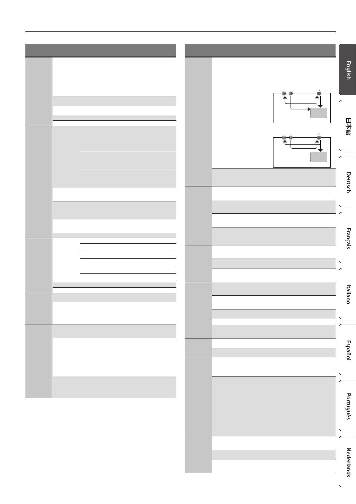
USBMIDI Thru OFF, ON
Species whether MIDI messages received
via the USB COMPUTER port/MIDI IN
connector will be re-transmitted from the
MIDI OUT connector/USB COMPUTER port
(ON) or not be re-transmitted (OFF).
Sound
Generator
Section
USB
IN
MIDI
IN
USB
OUT
MIDI
OUT
USBMIDI Thru=ON
JD-XA
USB
IN
MIDI
IN
USB
OUT
MIDI
OUT
USBMIDI Thru=OFF
JD-XA
Sound
Generator
Section
Soft Thru OFF, ON
If this is ON, MIDI messages that are
input from the MIDI IN connector are re-
transmitted without change from the MIDI
OUT connector.
MIDI TX
Tx Prog Chg OFF, ON
Species whether program change
messages will be transmitted (ON) or not be
transmitted (OFF).
Tx Bank Sel OFF, ON
Species whether bank select messages will
be transmitted (ON) or not be transmitted
(OFF).
Tx Actv Sens OFF, ON
Species whether active sensing messages
will be transmitted (ON) or not be
transmitted (OFF).
Tx Edit Data OFF, ON
Specify whether changes you make in the
settings of a program will be transmitted as
system exclusive messages (ON), or will not
be transmitted (OFF).
MIDI RX
Rx Prog Chg OFF, ON
Species whether program change
messages will be received (ON) or not be
received (OFF).
Rx Bank Sel OFF, ON
Species whether bank select messages will
be received (ON) or not be received (OFF).
Rx Exclusive OFF, ON
Species whether system exclusive
messages will be received (ON) or not be
received (OFF).
CV/GATE1/2
OUT
Ch Src
SYSTEM,
PROGRAM
Species whether the CV/GATE channel
setting will use the system setting (SYSTEM)
or the setting of the program (PROGRAM).
Ctrl Ch 1–16, OFF
Species the channel whose notes are
output from the CV OUT 1/2 and GATE OUT
1/2 jacks.
Ref Note C0–C4
Species the note number at which the CV
OUT is 0 V, in units of octaves.
Scale -63–+63 Adjusts the scale of the CV.
Fine Tune -50–+50
Adjusts the 0 V of the CV OUT.
* This value will uctuate slightly if the
Scale value is changed.
INDICATORS
Part OFF, ON
Turns on/o the indicator showing that a
part is producing sound.
Beat OFF, ON
Turns on/o the tempo-synchronized beat
indicator.
CONTROL
Src Sel
SYSTEM Sys Ctrl Src1–4 will be used for tone control.
PROGRAM
Tone Control Src 1–4 of the program will be
used for tone control.
Sys Ctrl1–4
OFF, CC, BEND,
AFT
Specify the MIDI messages that will be used
as system controls.
System Control settings allow you to specify
MIDI messages that will apply in common
to the entire JD-XA, and can be used for
controlling volume, tone, etc.
You can assign up to four MIDI messages for
this type of control.
If you want to make assignments for
realtime control of the sound and eects
for each tone independently, use “matrix
control” or “multi-eect control.
&
For details, refer to “Parameter Guide
(English)” (PDF).
MIC
NS Switch OFF, ON
Switches the noise suppressor on/o.
The noise suppressor is a function that
suppresses noise during periods of silence.
NS Threshold 0–127
Adjusts the volume at which noise
suppression starts to be applied.
NS Release 0–127
Adjusts the time from when noise
suppression starts until the volume reaches
0.
14
Overall Settings for the JD-XA
Menu
[Shift]+
Cursor [
K
] [
J
]
Parameter
Cursor [
K
] [
J
]
Value
[-] [+]
Explanation
MIC REVERB
Switch OFF, ON Switches the reverb on/o.
Type
ROOM1,
ROOM2,
STAGE1,
STAGE2, HALL1,
HALL2, DELAY,
PAN-DLY
Type of reverb
Time 0–127 Time length of reverberation
Level 0–127 Volume of the reverb sound
MASTER EQ
Switch OFF, ON Switches the master EQ on/o.
Input Gain -15 dB–+15 dB Adjusts the input gain of the master EQ.
Low Freq 16 Hz–800 Hz Frequency of the low range.
Low Gain -15 dB–+15 dB Gain of the low frequency range.
Mid1 Freq
16 Hz–16000
Hz
Frequency of the middle range 1.
Mid1 Gain -15 dB–+15 dB Gain of the middle frequency range 1.
Mid1 Q 0.5–8.0
Width of the middle frequency range 1.
Set a higher value for Q to narrow the range
to be aected.
Mid2 Freq
16 Hz–16000
Hz
Frequency of the middle range 2.
Mid2 Gain -15 dB–+15 dB Gain of the middle frequency range 2.
Mid2 Q 0.5–8.0
Width of the middle frequency range 2.
Set a higher value for Q to narrow the range
to be aected.
Mid3 Freq
16 Hz–16000
Hz
Frequency of the middle range 3.
Mid3 Gain -15 dB–+15 dB Gain of the middle frequency range 3.
Mid3 Q 0.5–8.0
Width of the middle frequency range 3.
Set a higher value for Q to narrow the range
to be aected.
HighFreq
630 Hz–16000
Hz
Frequency of the high range.
High Gain -15 dB–+15 dB Gain of the high frequency range.
Saving the System Settings
System settings revert to their previous state when you turn o the power. If you
want to keep these settings even after the power is turned o, you must save the
system settings.
1.
Press the [Write] button.
2.
Use the Cursor [K] [J] buttons to select “SYSTEM, and then press the [Enter]
button.
A conrmation message appears.
If you decide to cancel, press the [Exit] button.
3.
Press the [Enter] button.
A screen indicating “Completed!” appears, and the data is saved.
* NEVER turn the power o while you are saving settings.
MEMO
You can also save the system settings by pressing the [Write] button in the system
setting screen.
Convenient Functions (UTILITY)
These functions let you back up the JD-XAs internal data to a USB ash drive, or to
restore data from a USB ash drive into the JD-XA.
Other utility functions let you return the JD-XA to its factory-set state, or initialize a
USB ash drive.
1.
Press the [Menu] button.
2.
Use the Cursor [K] [J] buttons to select “UTILITY, and then press the [Enter]
button.
The UTILITY screen appears.
Menu items
Cursor [
K
] [
J
]
Explanation
BACKUP
Backs up data to a le with the name you specify.
System and user setting (. SVD) and pattern (. BIN) les are created.
&
“Backing Up Data (BACKUP)” (p. 15)
RESTORE
Restores data from the le you specify.
Data is restored from the system and user setting (. SVD) and
pattern (. BIN) les.
&
“Restoring Data (RESTORE)” (p. 15)
FACTORY RESET
&
“Returning to the Factory Settings (FACTORY RESET)”
(p. 15)
USB MEM FORMAT
&
“Formatting a USB Flash Drive (USB MEM FORMAT)”
(p. 14)
3.
Use the Cursor [K] [J] buttons to select the item that you want to edit, and
press the [Enter] button.
Formatting a USB Flash Drive (USB MEM FORMAT)
* Never turn o the power or remove the USB ash drives while the screen indicates “Executing.
* Carefully insert the USB ash drives all the way in—until it is rmly in place.
1.
Press the [Menu] button.
2.
Use the Cursor [K] [J] buttons to select “UTILITY, and then press the [Enter]
button.
3.
Use the Cursor [K] [J] buttons to select “USB MEM FORMAT, and then press
the [Enter] button.
A conrmation message appears.
Format USB Mem?
[Exit]:N [Ent]:Y
If you decide to cancel, press the [Exit] button.
4.
Press the [Enter] button to execute.
When formatting is complete, the following screen appears.
Completed!
The folder structure of a USB ash drive
EXPORT SMF folder
Exported SMF les are saved here.
IMPORT folder
Files that you want to import to the JD-XA should be copied here.
(File name) . SVD : Tone import
(File name) . MID : SMF import
JD-XA folder
ROLAND folder
JD-XA programs and backup data are saved here.
BACKUP folder
Backup data is saved here.
PROGRAM folder
Programs in the USB ash drive are
saved here.
A folder
Bank A program data
B folder
Bank B program data
P folder
Bank P program data
15
Overall Settings for the JD-XA
Restoring Backup Data from a USB Flash Drive
Use a USB ash drive sold by Roland. We cannot guarantee operation if any other
product is used.
Backing Up Data (BACKUP)
1.
Press the [Menu] button.
2.
Use the Cursor [K] [J] buttons to select “UTILITY, and then press the [Enter]
button.
UTILITY [Ent]
BACKUP
3.
Use the Cursor [K] [J] buttons to select “BACKUP, and then press the [Enter]
button.
The name input screen appears.
BACKUP NAME[Ent]
JDXA_BKUP .SVD
4.
Use the cursor [K] [J] buttons to move the cursor, and use the [-] [+] buttons
to select characters.
5.
When you’ve specied the name, press the [Enter] button.
A conrmation message appears.
Backup?
[Exit]:N [Ent]:Y
If you decide to cancel, press the [Exit] button.
6.
Press the [Enter] button.
Restoring Data (RESTORE)
NOTE
When you execute the restore operation, all user data is rewritten.
If the JD-XA contains important data, back it up on a USB ash drive using a
dierent name before you execute the restore operation.
1.
Press the [Menu] button.
2.
Use the Cursor [K] [J] buttons to select “UTILITY, and then press the [Enter]
button.
3.
Use the Cursor [K] [J] buttons to select “RESTORE, and then press the [Enter]
button.
4.
Use the [-] [+] buttons to select the le that you want to restore, and then
press the [Enter] button.
A conrmation message appears.
Restore?
[Exit]:N [Ent]:Y
If you decide to cancel, press the [Exit] button.
5.
Press the [Enter] button.
When restoring is complete, the following screen appears.
Completed.
Turn off power.
6.
Turn the power of the JD-XA o, then on again.
Returning to the Factory Settings (FACTORY RESET)
1.
Press the [Menu] button.
2.
Use the Cursor [K] [J] buttons to select “UTILITY, and then press the [Enter]
button.
3.
Use the Cursor [K] [J] buttons to select “FACTORY RESET, and then press
the [Enter] button.
A conrmation message appears.
Factory Reset?
[Exit]:N [Ent]:Y
If you decide to cancel, press the [Exit] button.
4.
Press the [Enter] button to execute.
5.
Turn the power of the JD-XA o, then on again.
Items initialized by Factory Reset
5
All user programs (including arpeggios, patterns, and eects)
5
System settings
5
LED CUSTOMIZE settings
Making the Power Automatically Turn O After a Time
(Auto O)
1.
Press the [Menu] button.
2.
Use the Cursor [K] [J] buttons to select “SYSTEM, and then press the [Enter]
button.
GENERAL:
Auto Off 30min
3.
Hold down the [Shift] button and use the cursor [K] [J] buttons to select
“GENERAL.
4.
Use the Cursor [K] [J] buttons to select Auto O and use the [-] [+] buttons
to change the setting.
If you don’t want the unit to turn o automatically, choose “OFF” setting.
5.
Press the [Exit] button several times to return to the program select screen.
Customizing the Knob and Slider Illumination (LED CUSTOMIZE)
By using the LED Customize settings you can control the way in which the LEDs
illuminate regardless of the Part Select status.
1.
Press the [Menu] button.
2.
Use the Cursor [K] [J] buttons to select “LED CUSTOMIZE, and then press
the [Enter] button.
3.
Use the [-] [+] buttons to specify the LED Customize parameter.
4.
Move the knobs and sliders to specify how you want the LEDs to illuminate.
5.
Press the [Write] button to save the settings.
MEMO
The LED illumination status changes (all lit
,
all unlit) each time you hold
down the [Shift] button and press the [Program Select] (Init) button in the LED
CUSTOMIZE screen.
16
List of Shortcut Keys
Shortcut Explanation
Part
[Shift]+ Part On [01]–[04] Turns part mute on/o (p. 4).
[Arpeggio]+ Part On [01]–[04] Turns each part’s Arpeggio Sw on/o (p. 9).
[Vocoder]+ Part On [01]–[04] Turns each part’s Vocoder Send Sw on/o.
Press Part On [01]–[04] + keyboard
twice (to specify the lower and
upper limit)
Species the key range of each part.
Controllers
[Shift]+[Modulation] lever
Enters the Modulation LFO setting state.
To exit this state, use [Shift] + [Modulation] lever once
again.
[Shift] + operate Wheel 1 Displays the Wheel 1 assignment (p. 12).
[Shift] + operate Wheel 2 Displays the Wheel 2 assignment (p. 12).
[Shift]+ operate Pedal 1 Displays the Pedal 1 assignment (p. 12).
[Shift]+ operate Pedal 2 Displays the Pedal 2 assignment (p. 12).
Common section
[Exit] + controller Displays the parameter (the value does not change).
[-], [+]
Hold down one button while pressing the other button to
make the value change rapidly.
[Shift]+[-] [+] Makes the value change more greatly.
[Shift]+[
K
] [
J
] Moves to the previous/next parameter section.
[Shift]+[MIDI CTRL] Turns trigger mode on/o (p. 11).
[Shift]+[Menu]
Display Lock on/o.
If this is on, the corresponding parameter is not displayed
when you move a controller (the value is changed).
[Shift]+[Write] Displays the LED Customize screen (p. 15).
[Shift]+[Enter] Executes the Manual function (p. 2).
[Shift]+[Program Select]
Displays the Init screen (p. 7).
(In the Arpeggio Edit screen, initializes the arpeggio
pattern.)
[Shift]+[Bank] Displays the Copy screen (p. 7).
[Shift]+[Favorite] Displays the Favorite Util screen (p. 7).
[Program Select]+[01]–[16] Selects a program
[Bank]+[01]–[16]
Normally: Switches the program bank (p. 4).
Favorites: Switches the favorite bank (p. 7).
[Favorite]+[01]–[16]
Registers the current program number as a favorite
(p. 7).
LFO
[Shift]+ [Tempo Sync]
Analog part: Turns LFO Key Trigger on/o.
Digital part: Turns LFO Key Trigger on/o.
[Shift]+ [AMP Depth]
Analog part: No function.
Digital part: Adjusts LFO Pan Depth.
OSC1
[Shift]+[Pitch]
Analog part: No function.
Digital part: Adjusts AMP Pan.
Part Select [01]–[04]+[Pitch] Adjust the pan of each part.
[Shift]+[PW]
Analog part: No function.
Digital part: Adjusts OSC PW Shift (Pulse Width Shift).
PITCH ENV
[Shift]+[Depth]
Analog part: Adjusts Pitch Env Velo Sens (Velocity Sens).
Digital part: No function.
FILTER
[Shift]+[Cuto]
Analog part: Adjusts FILTER Cuto Fine.
Digital part: No function.
[Shift]+[Key Follow]
Analog part: Adjusts FILTER KF Fine (Key Follow Fine).
Digital part: No function.
[Shift]+[Env Depth]
Analog part: Adjusts FILTER Velo Sens (Velocity Sens).
Digital part: Adjusts FILTER Velo Sens (Velocity Sens).
AMP
[Shift]+[Level]
Analog part: Adjusts AMP Velo Sens (Velocity Sens).
Digital part: Adjusts AMP Velo Sens (Velocity Sens).
Part Sel [01]–[04]+[AMP Level] Adjust the volume of each part.
EFFECTS
[Shift]+[TFX 1 On]
Displays the TFX 1 screen (TFX1 Sw setting does not
change).
[Shift]+[TFX 2 On]
Displays the TFX 2 screen (TFX2 Sw setting does not
change).
[Shift]+[Part MFX On]
Displays the Part MFX screen (Part MFX Sw setting does not
change).
Shortcut Explanation
PATTERN SEQ
[Shift]+[01]–[16]
[Pattern Length]+[01]–[16]
Use the [01]–[16] buttons to move the region (measures) of
performance data that is displayed (p. 8).
[01]–[16] + knob
(during Step REC2)
Records the knob operation at the specied step (position)
(p. 8).
Keyboard + [01]–[16]
(during Step REC2)
Records the keyboard note at the specied step (position).
[Shift]+[Erase] Displays the Pattern Erase menu (p. 9).
[Erase]+Part On [01]–[04]
Displays the Pattern Erase menu and assigns the specied
part as the target for erasure (p. 9).
[Erase]+[01]–[16]
Erases the all recorded data included in the specied step
of the applicable Step REC part (p. 8).
[Erase] + knob
During Realtime Erase: Assigns the knob data as the target
for erasure (p. 8).
[Shift]+[Step REC]
Displays the Step REC setting screen (p. 8).
(The Step REC status does not change)
[Shift]+[Realtime REC]
Displays the Realtime REC setting screen (p. 8).
(The Realtime REC status does not change)
[Shift]+[Tap] Displays the tempo parameter.
At the left side of the keyboard
[Shift]+OCTAVE [Up] [Down] Sets Tone Common Oct Shift (Octave Shift).
[Shift]+[Key Hold]
Switches the Kbd Velocity setting (Real
,
xed value
(default:127)) (p. 12).
[Shift]+[Arpeggio]
Displays the arpeggio screen (p. 9).
(The arpeggio switch does not change)
&
For details on the parameters, refer to “Parameter Guide (English)” (PDF).
* “[A]+[B]” indicates the operation of “holding down the [A] button and pressing the [B] button.
  • Page 1 1
  • Page 2 2
  • Page 3 3
  • Page 4 4
  • Page 5 5
  • Page 6 6
  • Page 7 7
  • Page 8 8
  • Page 9 9
  • Page 10 10
  • Page 11 11
  • Page 12 12
  • Page 13 13
  • Page 14 14
  • Page 15 15
  • Page 16 16
  • Page 17 17
  • Page 18 18
  • Page 19 19
  • Page 20 20
  • Page 21 21
  • Page 22 22
  • Page 23 23
  • Page 24 24
  • Page 25 25
  • Page 26 26

Roland JD-XA Owner's manual

Category
Sequencer
Type
Owner's manual

Ask a question and I''ll find the answer in the document

Finding information in a document is now easier with AI