Panasonic CQ-C1325N User manual

Category
Car media receivers
Type
User manual

This manual is also suitable for

YFM284C646CA PTW1206-1106 Printed in China
Matsushita Electric Industrial Co., Ltd.
Web Site: http://panasonic.net
Sales and Support Information
For UK and Ireland customers only.
Customer Care Centre
¡ For customers within the UK: 08705 357357
¡ For customers within the Republic of Ireland: 01 289 8333
¡ Visit our website for product information
Direct Sales at Panasonic UK
¡ Order accessories and consumable items for your product
with ease and confidence by phoning our Customer Care
Centre Monday - Thursday 9:00am - 5:30pm, Friday
9:30am - 5:30pm. (Excluding public holidays).
¡ Or go on line through our Internet Accessory ordering
application at www.panasonic.co.uk.
¡ Most major credit and debit cards accepted.
¡ All enquiries, transactions and distribution facilities are
provided directly by Panasonic UK Ltd.
¡ It couldn't be simpler!
¡ Also available through our Internet is direct shopping for a
wide range of finished products, so take a browse on our
website for further details.
Accessories
Operating Instructions
(English : YFM284C646CA)
(Deutsch : YFM284C647CA)
(Français : YFM284C648CA)
(Italiano : YFM284C649CA)
(Español : YFM284C650CA)
Q'ty: 1 set
Installation Instructions
(English, Deutsch, Français
: YFM294C081CA)
(Italiano, Español
: YFM294C082CA)
Q'ty: 1 set
PAN EUROPEAN GUARANTEE
(Warranty Card)
Q'ty: 1
Installation kit (ZZBISC1021N-J)
Lock Cancel Plate
Q'ty: 2
Mounting Bolt
Q'ty: 1
Mounting Collar
(FX0214C384ZB)
Q'ty: 1
Trim Plate
(YFC054C079YA)
Q'ty: 1
Power Connector
(YEAJ02874)
Q'ty: 1
Notes:
¡ The number in parentheses underneath
each accessory part name is the part
number for maintenance and service.
¡ Accessories and their part numbers are
subject to modification without prior
notice due to improvements.
¡ Mounting Collar and Trim Plate are
mounted on the main unit at shipment.
MP3 CD Player/Receiver
Model: CQ-C1325N/C1315N
Operating Instructions
¡Please read these instructions carefully before using this product and keep this manual for future reference.
D
·
M
CQ-C1325N
MUTE
RANDOMSCROLL SCAN REPEAT
SQ
V
O
L
U
M
E
T
U
N
E
/
T
R
A
C
K
F
O
L
D
E
R
123456
BAND
SRC
SEL
PWR
APM
DISP
CLOCK
(CQ-C1325N)
TEXT
English
Caution
Observe the following cautions when using this
unit.
Keep the sound volume at an appropriate level.
Keep the volume level low enough to be aware of road and traffic
conditions while driving.
This unit is designed for use exclusively in automobiles.
Do not operate the unit for a prolonged period with the
engine turned off.
Operating the audio system for a long period of time with the
engine turned off will drain the battery.
Do not expose the unit to direct sunlight or excessive
heat.
Otherwise these will raise the interior temperature of the unit, and
it may lead to smoke, fire, or other damage to the unit.
Do not use the product where it is exposed to water,
moisture, or dust.
Exposure of the unit to water, moisture, or dust may lead to
smoke, fire, or other damage to the unit. Make especially sure that
the unit does not get wet in car washes or on rainy days.
Observe the following cautions when installing.
Refer wiring and installation to qualified service personnel.
Installation of this unit requires special skills and experience. For
maximum safety, have it installed by your dealer. Panasonic is not
liable for any problems resulting from your own installation of the
unit.
Follow the instructions to install and wire the product.
Not following the instructions to properly install and wire the prod-
uct could cause an accident or fire.
Take care not to damage the leads.
When wiring, take care not to damage the leads. Prevent them
from getting caught in the vehicle chassis, screws, and moving
parts such as seat rails. Do not scratch, pull, bend or twist the
leads. Do not run them near heat sources or place heavy objects
on them. If leads must be run over sharp metal edges, protect the
leads by winding them with vinyl tape or similar protection.
Use the designated parts and tools for installation.
Use the supplied or designated parts and appropriate tools to
install the product. The use of parts other than those supplied or
designated may result in internal damage to the unit. Faulty instal-
lation may lead to an accident, a malfunction or fire.
Do not block the air vent or the cooling plate of the unit.
Blocking these parts will cause the interior of the unit to overheat
and will result in fire or other damage.
Do not install the product where it is exposed to strong
vibrations or is unstable.
Avoid slanted or strongly curved surfaces for installation. If the
installation is not stable, the unit may fall down while driving and
this can lead to an accident or injury.
Installation Angle
The product should be installed in a horizontal position with the
front end up at a convenient angle, but not more than 30˚.
The user should bear in mind that in some areas there may be
restrictions on how and where this unit must be installed. Consult
your dealer for further details.
Wear gloves for safety. Make sure that wiring is complet-
ed before installation.
To prevent damage to the unit, do not connect the power
connector until the whole wiring is completed.
Do not connect more than one speaker to one set of
speaker leads. (except for connecting to a tweeter)
Safety Information
Warning
Observe the following warnings when using this
unit.
The driver should neither watch the display nor operate
the system while driving.
Watching the display or operating the system will distract the driv-
er from looking ahead of the vehicle and can cause accidents.
Always stop the vehicle in a safe location and use the parking
brake before watching the display or operating the system.
Use the proper power supply.
This product is designed for operation with a negative grounded
12 V DC battery system. Never operate this product with other bat-
tery systems, especially a 24 V DC battery system.
Protect the Deck Mechanism.
Do not insert any foreign objects into the slot of this unit.
Do not disassemble or modify the unit.
Do not disassemble, modify the unit or attempt to repair the prod-
uct yourself. If the product needs to be repaired, consult your
dealer or an authorized Panasonic Service Centre.
Do not use the unit when it is out of order.
If the unit is out of order (no power, no sound) or in an abnormal
state (has foreign objects in it, is exposed to water, is smoking, or
smells), turn it off immediately and consult your dealer.
Refer fuse replacement to qualified service personnel.
When the fuse burns out, eliminate the cause and have it replaced
with the fuse prescribed for this unit by a qualified service engi-
neer. Incorrect replacement of the fuse may lead to smoke, fire,
and damage to the product.
Observe the following warnings when installing.
Disconnect the lead from the negative (–) battery termi-
nal before installation.
Wiring and installation with the negative (–) battery terminal con-
nected may cause electrical shock and injury due to a short circuit.
Some cars equipped with the electrical safety system have specific
procedures of battery terminal disconnection.
FAILURE TO FOLLOW THE PROCEDURE MAY LEAD TO THE
UNINTENDED ACTIVATION OF THE ELECTRICAL SAFETY SYSTEM
RESULTING IN DAMAGE TO THE VEHICLE AND PERSONAL
INJURY OR DEATH.
Never use safety-related components for installation,
grounding, and other such functions.
Do not use safety-related vehicle components (fuel tank, brake,
suspension, steering wheel, pedals, airbag, etc.) for wiring or fix-
ing the product or its accessories.
Installing the product on the air bag cover or in a location
where it interferes with airbag operation is prohibited.
Check for piping, gasoline tank, electric wiring, and other
items before installing the product.
If you need to open a hole in the vehicle chassis to attach or wire
the product, first check where the wire harness, gasoline tank, and
electric wiring are located. Then open the hole from outside if pos-
sible.
Never install the product in a location where it interferes
with your field of vision.
Never have the power cord branched to supply other
equipment with power.
After installation and wiring, you should check the nor-
mal operation of other electrical equipment.
The continuation of their using in abnormal conditions may cause
fire, electrical shock or a traffic accident.
In the case of installation to an airbag-equipped car, con-
firm warnings and cautions of the vehicle manufacturer
before installation.
Make sure the leads do not interfere with driving or get-
ting in and out of the vehicle.
Insulate all exposed wires to prevent short circuiting.
This pictograph intends to alert you to the presence of
important operating instructions and installation
instructions. Failure to heed the instructions may
result in severe injury or death.
Read the operating instructions for the unit and all other compo-
nents of your car audio system carefully before using the system.
They contain instructions about how to use the system in a safe and
effective manner. Panasonic assumes no responsibility for any prob-
lems resulting from failure to observe the instructions given in this
manual.
This manual uses pictographs to show you how to use the product
safely and to alert you to potential dangers resulting from improper
connections and operations. The meanings of the pictographs are
explained below. It is important that you fully understand the mean-
ings of the pictographs in order to use this manual and the system
properly.
Warning
This pictograph intends to alert you to the presence of
important operating instructions and installation instruc-
tions. Failure to heed the instructions may result in
injury or material damage.
Caution
Before Reading These Instructions
Panasonic welcomes you to our constantly growing family of electronic products owners.
We endeavor to give you the advantages of precise electronic and mechanical engineering, manufactured with carefully selected components, and
assembled by people who are proud of the reputation their work has built for our company. We know this product will bring you many hours of
enjoyment, and after you discover the quality, value and reliability we have built into it, you too will be proud to be a member of our family.
This operating instructions is for 2 models CQ-C1325N and CQ-C1315N. All illustrations throughout this manual represent
model CQ-C1325N unless otherwise specified. The following table describes the differences between 2 models.
Laser Product
Label Indications and Their Locations
CAUTION
LASER RADIATION WHEN OPEN. DO NOT STARE
INTO BEAM.
Caution
This product utilizes a laser.
Use of controls or adjustments or performance of
procedures other than those specified herein may
result in hazardous radiation exposure.
Do not take apart this unit or attempt to
make any changes yourself.
This unit is a very intricate device that uses a laser
pickup to retrieve information from the surface of
compact discs. The laser is carefully shielded so that
its rays remain inside the cabinet.
Therefore, never try to disassemble the player or alter
any of its parts since you may be exposed to laser
rays and dangerous voltages.
Caution Label
Deck Ass’y (in the unit,
upper side)
Preparation
Clock Setting
CLASS 1 LASER PRODUCT
Notes on Discs
If you use commercial CDs, they must have the label
shown at right.
Some copy-protected music CDs are not playable.
¡ You may have trouble playing back some CD-R/RW discs
recorded using CD recorders (CD-R/RW drives), either due
to their recording characteristics or dirt, fingerprints,
scratches, etc. on the disc surface.
¡ CD-R/RW discs are less resistant to high temperatures and
high humidity than ordinary music CDs. Leaving them
inside a car for extended periods may damage them and
make playback impossible.
¡ Some CD-R/RWs cannot be played back successfully due
to incompatibility among writing software, a CD recorder
(CD-R/RW drive) and the discs.
¡ This player cannot play the CD-R/RW discs if the session is
not closed.
¡ This player cannot play the CD-R/RW discs which contain
other than CD-DA or MP3 data.
¡ Be sure to observe the instructions of the CD-R/RW disc
for handling it.
Recording MP3 files on a CD-media
¡ You are recommended to minimize the chances of mak-
ing a disc that contains both CD-DA files and MP3 files.
¡ If CD-DA files are on the same disc as MP3 files, the
songs may not play in the intended order, or some songs
may not play at all.
¡ Do not record files other than MP3 files and unnecessary
folder on a disc.
¡ The name of MP3 file should be added by rules as shown in
the following descriptions and also comply with the rules of
each file system.
¡ You may encounter trouble in playing MP3 files or display-
ing the information of MP3 files recorded with certain writ-
ing software or CD recorders.
¡ The file extension “.mp3” should be assigned to each file
depending on the file format.
¡ This unit does not have the play list function.
¡ Although Multi-session recording is supported, the use of
Disc-at-Once is recommended.
Supported file systems
ISO 9660 Level 1/Level 2, Apple Extension to ISO 9660, Joliet,
Romeo
Note: Apple HFS, UDF 1.50, MIX mode CD, CD Extra is not
supported.
Compression formats
(Recommendation: “Points to remember when making
MP3 files” on the right.)
Notes on CD/CD Media
(CD-ROM, CD-R, CD-RW)
Notes on CD-Rs/RWs
Notes on MP3
Note: MP3 encoding and writing software is not supplied
with this unit.
Points to remember when making MP3 files
MP3
¡ High bit rate and high sampling frequency are recommend-
ed for high quality sounds.
¡ Selecting VBR (Variable Bit Rate) is not recommended
because playing time is not displayed properly and sound
may be skipped.
¡ The playback sound quality differs depending on the encod-
ing circumstances. For details, refer to the user manual of
your own encoding software and writing software.
¡ It is recommended to set the bit rate to “128 kbps or more”
and “fixed”.
Display Information
Displayed items
Displayable characters
¡ Displayable length of file name/folder name: within 32
characters. (Unicoded file and folder names are reduced by
half in the number of displayable characters.)
¡ Name files and folders in accordance with the standard of
each file system. Refer to the instructions of writing soft-
ware for details.
¡ ASCII character set and special characters in each language
can be displayed.
Notes:
¡ With some software in which MP3 format files have been
encoded, the character information may not be displayed
properly.
¡ Undisplayable characters and symbols will be converted
into an asterisk ( ).
Folder selection order/file playback order
Maximum number of files/folders
¡ Maximum number of files: 999
¡ Maximum number of files in one folder: 255
¡ Maximum depth of trees: 8
¡ Maximum number of folders: 255 (Root folder is included.)
Notes:
¡ This unit counts the number of folders irrespective of the
presence or absence of an MP3 file.
¡ If the selected folder does not contain any MP3 files, the
nearest MP3 files in the order of playback will be played.
¡ Playback order may be different from other MP3 players
even if the same disc is used.
¡ “ROOT” appears when displaying the root folder name.
Copyright
It is prohibited by copyright laws to copy, distribute and deliv-
er copyrighted materials such as music without the approval
of copyright holder except enjoying yourself personally.
No warranty
Above description complies with our investigations as of
September 2006. It has no warranty for reproducibility and
displayability of MP3.
Root Folder
(Root Directory)
Folder Selection
File Selection
Tree 1 Tree 2 Tree 3 Tree 4 Tree 8
(Max.)
2
1
3
4
5
6
8
18
7
In the order
In the order
Caution
¡ Never assign the “.mp3” file name exten-
sion to a file that is not in the MP3 format.
This may not only produce noise from the
speaker damage, but also damage your
hearing.
¡ CD-TEXT
Disc title
Track title
¡ MP3
Folder name
File name
¡ MP3 (ID3 tag)
Album name
Title name/Artist name
Notes on MP3
¡ MPEG 1 audio layer 3
Bit rate: 32 k-320 kbps
VBR: Yes
Sampling frequency:
32, 44.1, 48 kHz
¡ MPEG 2 audio layer 3
Bit rate: 8 k-160 kbps
VBR: Yes
Sampling frequency:
16, 22.05, 24 kHz
Specifications
Notes:
¡ Specifications and design are subject to modification without notice due to improvements.
¡ Some figures and illustrations in this manual may be different from your product.
General
Sampling frequency 8 times oversampling
DA converter 1 bit DAC System
Pick-up type Astigma 3 – beam
Light source Semiconductor laser
Wave length 790 nm
Frequency response 20 Hz – 20 kHz (±1 dB)
Signal to noise ratio 96 dB
Wow and flutter Below measurable limits
Channel separation 75 dB
FM
Frequency Range 87.5 MHz – 108 MHz
Usable Sensitivity 6 dB/µV (S/N 30 dB)
Stereo Separation 35 dB (at 1 kHz)
AM (MW)
Frequency Range 531 kHz – 1 602 kHz
Usable Sensitivity 28 dB/µV (S/N 20 dB)
Disc Player
Maintenance
Your product is designed and manufactured to ensure the minimum of maintenance. Use a dry, soft cloth for routine
exterior cleaning. Never use benzine, thinner, or other solvents.
Cleaning the
Unit
Fuse
Anti-Theft System
This unit is equipped with a removable face plate. Removing this face plate makes the unit totally inoperable.
Removing
1
Turn off the power.
2
Press []. The face plate will open.
3
Pull it out toward you.
Mounting
1
Slide the left side of the face plate in place.
2
Press the right end of face plate until a
“click” is heard.
Caution
¡ This face plate is not waterproof. Do not expose it to
water or excessive moisture.
¡ Do not remove the face plate while driving your car.
¡ Do not place the face plate on the dashboard or nearby
areas where the temperature rises high.
¡ Do not touch the contacts on the face plate and the main
unit, since this may result in poor electrical contact.
¡ If dirt or other foreign substances get on the contacts,
wipe them off with a clean and dry cloth.
Face Plate Removing/Mounting
(Anti-Theft System)
If the replaced fuse fails, contact your nearest authorized Panasonic Service Centre.
Warning
¡ Use fuses of the same specified rating (15 A). Using substitutes or fuses with higher ratings, or connecting the unit direct-
ly without a fuse could cause fire or damage to the unit. If the replaced fuse fails, contact your nearest authorized
Panasonic Service Centre.
2
1
2
1
CQ-C1325N/C1315N 01-Eng-1 YFM284C646CA 1
Models CQ-C1325N CQ-C1315N
LCD background colour Blue Black
Information on Disposal for Users of Waste Electrical & Electronic Equipment (private households)
This symbol on the products and/or accompanying documents means that used electrical and electronic products should not
be mixed with general household waste.
For proper treatment, recovery and recycling, please take these products to designated collection points, where they will be
accepted on a free of charge basis. Alternatively, in some countries you may be able to return your products to your local
retailer upon the purchase of an equivalent new product.
Disposing of this product correctly will help to save valuable resources and prevent any potential negative effects on human
health and the environment which could otherwise arise from inappropriate waste handling. Please contact your local authority for further
details of your nearest designated collection point.
Penalties may be applicable for incorrect disposal of this waste, in accordance with national legislation.
For business users in the European Union
If you wish to discard electrical and electronic equipment, please contact your dealer or supplier for further information.
Information on Disposal in other Countries outside the European Union
This symbol is only valid in the European Union.
If you wish to discard this product, please contact your local authorities or dealer and ask for the correct method of disposal.
Power supply DC 12 V (11 – 16 V), test voltage 14.4 V, negative ground
Current consumption Less than 2.2 A (CD mode; 0.5 W x 4 channels)
Tone adjustment range Bass: ±12 dB at 100 Hz, Treble: ±12 dB at 10 kHz
Dimensions (W x H x D) 178 x 50 x 155 mm
Weight 1.3 kg
Maximum power output 45 W x 4 channels (at 1 kHz), volume control maximum
Power output 20 W x 4 (DIN 45 324, at 4 )
Speaker impedance 4 – 8
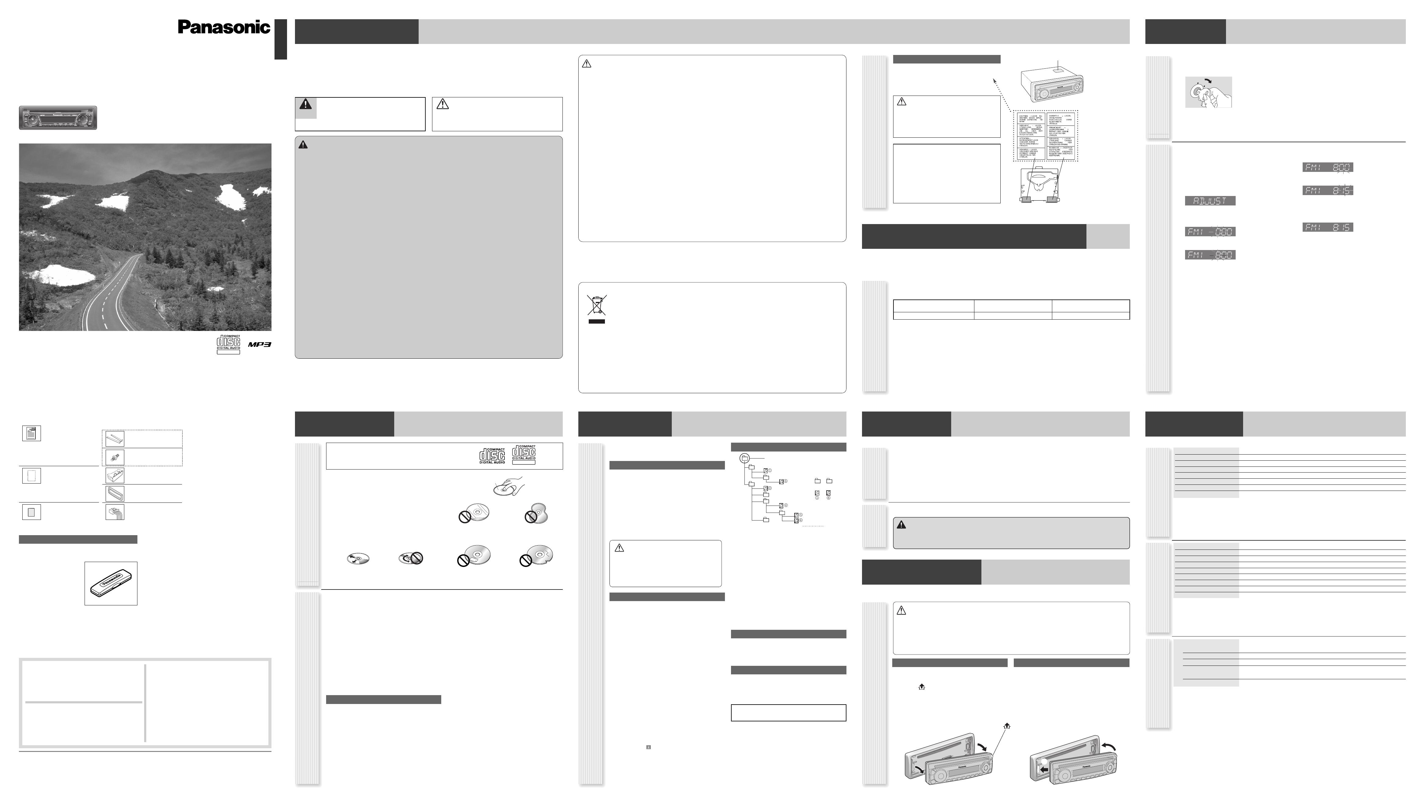
The 24-hour system is used for the clock.
Notes:
¡ Adjust the clock when “ADJUST” appears on the dis-
play.
¡ Hold down []] or [[] to change numbers rapidly.
1
Press [DISP].
(clock display)
2
Hold down [DISP] for more than 2 sec-
onds.
Hour blinks.
3
Adjust the hour.
Hour entered.
[[]: sets the hour ahead.
[]]: sets the hour back.
4
Press [DISP].
Minute blinks.
5
Adjust the minute.
Minute entered.
[[]: sets the minute ahead.
[]]: sets the minute back.
6
Press [DISP].
Completed
TEXT
[]
1
Set your car's ignition switch to the ACC
or ON position.
2
Press [SRC] (PWR: Power).
ACC
ON
Radio
Request for use of the Removable Face Plate Case
¡ To avoid trouble and ensure safety, use the optional
Removable Face Plate Case (YFC054C061ZB).
(YFC054C061ZB)
First Time Power On
How to hold the disc
¡ Do not touch the underside of the disc.
¡ Do not scratch on the disc.
¡ Do not bend the disc.
¡ When not in use, keep the disc in a case.
Do not leave discs in the following places:
¡ In direct sunlight
¡ Near car heaters
¡ Dirty, dusty and damp areas
¡ On seats and dashboards
Disc cleaning
Use a dry, soft cloth to wipe from the center outward.
Do not write on the disc label with a ballpoint pen
or other hard-point pens.
Labels created by a printer,
Protective films or sheets
Irregularly shaped discs
Printed side
<Wrong><Correct>
Disc with adhered
stickers or tape
Discs with cracks,
scratches or parts missing
MPEG Layer-3 audio coding technology licensed from
Fraunhofer IIS and Thomson.
Differences
between 2 models
D
·
M
CQ-C1325N
MUTE
RANDOMSCROLL SCAN REPEAT
SQ
V
O
L
U
M
E
T
U
N
E
/
T
R
A
C
K
F
O
L
D
E
R
123456
BAND
SRC
SEL
PWR
APM
DISP
CLOCK
DISP
SEL
D
·
M
CQ-C1325N
MUTE
RANDOMSCROLL SCAN REPEAT
SQ
V
O
L
U
M
E
T
U
N
E
/
T
R
A
C
K
F
O
L
D
E
R
123456
BAND
SRC
SEL
PWR
APM
DISP
CLOCK
BAND
3 4 5 6
SRC
DISP
D
·
M
CQ-C1325N
MUTE
RANDOMSCROLL SCAN REPEAT
SQ
V
O
L
U
M
E
T
U
N
E
/
T
R
A
C
K
F
O
L
D
E
R
123456
BAND
SRC
SEL
PWR
APM
DISP
CLOCK
BAND
1 2 3 4 5 6
SRC
DISP
D
·
M
CQ-C1325N
MUTE
RANDOMSCROLL SCAN REPEAT
SQ
V
O
L
U
M
E
T
U
N
E
/
T
R
A
C
K
F
O
L
D
E
R
123456
BAND
SRC
SEL
PWR
APM
DISP
CLOCK
SRC
CQ-C1325N/C1315N 01-Eng-2 YFM284C646CA 1
General
General Operations
Power On/Off
Set your car's ignition switch to the ACC or ON position.
Power on: Press [SRC] (PWR).
Power off: Hold down [SRC] (PWR) for more
than 1 second.
Source Selection
Press [SRC] to change the source.
Volume Adjustment
(Setting Range: 0 to 40, Default: 18)
Press [VOLUME
] or [VOLUME].
Mute
ON: Press [MUTE]. ( lights.)
OFF: Press [MUTE] again.
SQ (Sound Quality)
SQ is a function that can call up various sound types at the
touch of button in accordance with your listening music
type.
Press [SQ] to select the sound type as follows:
Note: Settings of SQ, bass and treble are influenced one
another. If such an influence causes distortion to the audio
signal, readjust bass/treble or volume.
[MUTE]
toggles mute on/off.
[VOLUME
] [VOLUME]
(FLAT) flat frequency response:
does not emphasize any part. (Default)
(ROCK) speedy and heavy sound:
exaggerates bass and treble.
(POP) wide-ranged and deep sound:
slightly emphasizes bass and treble.
(VOCAL) clear sound:
emphasizes middle tone and slightly empha-
sizes treble.
Troubleshooting
Trouble
Check point
No power
Start the engine. (Or turn the ignition
switch to the ACC position.)
Verify the wiring. (battery lead, power
lead, ground lead, etc.)
Fuse blown (Contact the nearest
Panasonic Service Centre.)
Ask a professional for fuse replacement.
Be sure to use the same rated fuse.
No sound
Disable the mute function.
Verify the wiring.
Wait until the dew disappears before
turning on the unit.
Noise
Make sure that grounding is established
properly.
Common
Frequent
noise
Tune in to another station of high-inten-
sity waves.
Make sure that the antenna mounted
point is grounded properly.
Radio
Preset data
deleted
The preset memory is cleared to return
to the original factory setting when the
power connector or battery is discon-
nected.
No sound, or disc
is automatically
ejected
Load the disc correctly.
Clean the disc.
Disc Player
Sound skip,
poor sound
quality
Clean the disc.
Sound skip
due to
vibration
The maximum permissible tilt angle is
30°.
Secure the unit.
Disc not
ejectable
Press [u]. If the disc is still not
ejected, contact the nearest Panasonic
Service Centre.
No sound from
left, right, front,
or rear speaker
Adjust the balance and fader.
Verify the wiring.
Trouble
Check point
Left and right
sounds are
reversed
Connect the speaker lead correctly.
Error Display Messages
(The disc is ejected automatically.)
The disc is dirty, or is upside down.
The disc has scratches.
Check the disc.
No operation by some cause.
If normal operation is not restored, con-
sult your dealer or the nearest Service
Centre to ask for repairs.
Cannot read the file
Check the file.
If You Suspect Something Wrong
Check and take steps as described below.
If the described suggestions do not solve the problem, it is recom-
mended to take the unit to your nearest authorized Panasonic Service
Centre. The product should be serviced only by qualified personnel.
Please refer the checking and the repair to professionals. Panasonic
shall not be liable for any accidents arising out of neglect of checking
the unit or your own repair after your checking.
Never take measures especially for those other than indicat-
ed by italic letters in “Check point” described below because
those are too dangerous for users to handle themselves.
Warning
¡ Do not use the unit in an irregular condition, for example, with-
out sound, or with smoke or a foul smell, which can cause
ignition or electric shock. Immediately stop using the unit and
consult your dealer.
¡ Never try to repair the unit by yourself because it is dangerous
to do so.
Radio (AM [MW]/FM)
[TUNE ]] [TUNE []
down/up the frequency. (Hold it down for more
than 0.5 seconds and release it for seek tuning.)
[BAND]
selects a band in the radio source.
(APM) (
Auto Preset Memory)
executes APM in the radio source.
(Hold it down for more than 2 seconds.)
Preset buttons [1] to [6]
selects a preset station in the radio
source, and presets the current
station. (Hold it down for more
than 2 seconds.)
Station Preset
Up to 6 stations can be preset in AM (MW), FM1, FM2, and
FM3 respectively.
Preset stations can be simply called up by pressing one of the
preset buttons from [1] to [6].
Auto Preset Memory (APM)
With this operation, stations with good receiving conditions can
be automatically stored in the preset memory.
1
Select a band.
2
Hold down [BAND] (APM) for more than 2
seconds.
The preset stations under best receiving conditions are
received for 5 seconds each after presetting the stations
(SCAN). To stop scanning, press one of the buttons from
[1] to [6].
Note: New stations overwrite existing saved stations.
Manual station preset
1
Tune into a station.
2
Hold down one of the preset buttons from
[1] to [6] for more than 2 seconds.
(blinks once)
Note: New stations overwrite existing saved stations.
lights while receiving an FM stereo signal.
Frequency Preset Number
Band
Display change
Press [DISP] to change the display.
Radio Source Display
Operation Flow
1
Press [SRC] to select the radio source.
2
Press [BAND] to select a band.
3
Select a station.
Frequency adjustment
[TUNE ]]: Lower
[TUNE []: Higher
Note: Hold down either of them for more than 0.5 sec-
onds and release it for seek tuning.
Preset station selection
Press the corresponding preset button from [1] to [6] to
tune into a preset station.
AM (MW) mode:
Band/frequency
Clock
FM mode:
Disc Player
Operation Flow
1
Press [SRC] to select the Disc Player
source.
2
Select a desired portion.
Track/file selection
Press [6] / [7].
Note: To perform fast forward/reverse, hold down either
of them.
Disc Player (CD-DA disc):
Previous/next track
Disc Player (MP3 disc):
Previous/next file
Folder selection (MP3)
Disc Player (MP3 disc):
Press [
{] / [}].
Skip to the previous/next folder.
Pause
Press [BAND] (
y
/
5
).
Press again to cancel.
Random play
All the available songs (tracks/files) are played in a random
sequence.
Press [4] (RANDOM).
Press again to cancel.
Folder random play (MP3)
All the available files in current folder are played in a random
sequence.
Hold down [4] (RANDOM) for more than 2
seconds.
Hold down again to cancel.
Repeat play
The current song (track/file) is repeated.
Press [6] (REPEAT).
Press again to cancel.
Folder repeat play (MP3)
The current folder is repeated.
Hold down [6] (REPEAT) for more than 2
seconds.
Hold down again to cancel.
Scan play
The first 10 seconds of each songs (tracks/files) is played in
sequence.
Press [5] (SCAN).
Press again to cancel.
Folder scan play (MP3)
From the next folder, the first 10 seconds of the first file on
each folder is played in sequence.
Hold down [5] (SCAN) for more than 2
seconds.
Hold down again to cancel.
Player Source Display
Notes:
¡ For scrolling text, press [3] (SCROLL).
¡ “NO TEXT” is displayed when there is no information on the
disc.
Caution
¡ Do not insert a disc when the indicator lights.
¡ Refer to the section of “Notes on Discs” and “Notes on
MP3”.
¡ This unit does not support 8 cm discs.
¡ If you insert an 8 cm disc and cannot eject it, turn the ignition key
to the ACC OFF position once and turn the key to the ACC ON
position again, then press [u] (Eject).
¡ Do not insert foreign objects into the disc slot.
Audio Settings
1
Press [SEL]
(Select
) to display the audio menu display.
Note: If no operation takes place for more than 5 seconds in the audio menu (2 seconds in Main volume adjust-
ment), the display returns to the regular mode.
2
Press
[SEL]
(Select
)
to select a mode to
be adjusted.
3
Press [] or [] to adjust.
(Setting Range: 0 to 40, Default: 18)
q : Up
w : Down
(Setting Range: –12 dB to +12 dB by 2 dB,
Default: 0 dB)
q : Increased
w : Decreased
(Setting Range: –12 dB to +12 dB by 2 dB,
Default: 0 dB)
q : Increased
w : Decreased
(Setting Range: 15 levels each, Default CNT (cen-
tre))
q : Right enhanced
w : Left enhanced
(Setting Range: 15 levels each, Default CNT (cen-
tre))
q :
Front enhanced
w :
Rear enhanced
Volume
Bass
Treble
Balance
Fader
Disc slot
takes a disc in with the printed side facing
up.
Note: A disc which has both CD-DA data
and MP3 data on it may not be reproduced
normally.
(
y
/
5
) (Pause/Play)
toggles pause/play in the
player source.
[DISP] (Display)
switches the information on the
display.
[6] [7]
skips to the previous/next
track/file in the player source.
Hold down either of them for fast
reverse/fast forward.
[3] (SCROLL)
scrolls the information on display.
[
{] [}]
skips to the previous/next folder.
[u] (Eject)
ejects the disc.
indicator
[4] (RANDOM)/[5] (SCAN)/[6] (REPEAT)
toggles on/off each play mode.
[SRC] (Source)
selects a source.
[DISP] (Display)
exits from the audio
menu.
[
] [
]
selects a value in the audio menu.
Display change
Press [DISP] to change the display.
Disc Player (CD-DA disc):
Disc Player (MP3 disc):
Play time
Normal
Folder name/
Album
*
*
File name/
Title, artist*
Clock
[DISP] (Display) (CLOCK)
switches the information on the display.
sets the clock time.
Disc title
Normal
Track title
Clock
[SRC] (Source)
selects a source.
[SRC] (Source)
selects a source.
(PWR) (Power)
toggles power on/off.
*ID3 Tag On/Off
Hold down [3] for more
than 2 seconds.
album title and song
title/artist name are dis-
played.
(Default)
folder name/file name are
displayed.
Printed side
lights when mute is on.
CD-DA mode display
Track number
Random indicator
Play time
Repeat indicator
MP3 mode display
Folder number
Random indicator
File number
Repeat indicator
Up
Down
[SQ] (Sound Quality)
selects a sound type (SQ).
Radio
Disc Player
Band/frequency
Clock
[SEL] (Select)
selects items in the audio menu.
Memorandum Memorandum Memorandum
(Stereo) indicator
Random, Repeat, Scan
Note: The Random/Repeat indicator will blink
when the folder random/repeat is on.
Audio Menu
0 – 30°
53 mm
182 mm
4.5 mm – 6.0 mm
D
·
M
Please read these instructions carefully before using this product and keep this manual for future reference.
Bitte lesen Sie diese Bedienungsanleitung vor der Verwendung dieses Produktes aufmerksam durch und bewahren
Sie sie danach für spätere Nachschlagzwecke sorgfältig auf.
Prière de lire ces instructions attentivement avant d’utiliser le produit et garder ce manuel pour l’utilisation ultérieure.
YFM294C081CA PTW1206-1116 Printed in China
Matsushita Electric Industrial Co., Ltd.
Web Site : http://panasonic.net
Consult a professional for installation.
Verify the radio using the antenna and speakers before installation.
Wenden Sie sich zum Einbau an einen Fachmann.
Probieren Sie den Radiobetrieb vor dem Einbau mit Antenne
und Lautsprechern aus.
Prenez contact avec un spécialiste pour le montage.
Vérifiez l’autoradio avant de procéder au montage.
Mounting angle side to side : horizontal
front to rear : 0 – 30°
Montagewinkel seitlich : horizontal
vorne-hinten : 0 – 30°
Angle de montage latéral : horizontal
longitudinal : 0 – 30°
Mounting space
Einbauöffnung
Espace nécessaire pour le montage
Before Installation/Vor dem Einbau/
Avant l’installation
Before Wiring/Vor der Verdrahtung/
Avant le câblage
How to install the unit/Einbau des Gerätes/Mode de montage de l’appareil
Supplied Hardware/
Mitgeliefertes Zubehör
/Matériel d’installation
1
1
1
1
2
No. Diagram
Q’ty
Item No. Diagram
Q’ty
Item
Mounting Collar
Einbauhalterung
Cadre de montage
Mounting Bolt (5 mm ø)
Befestigungsschraube (5 mm ø)
Boulon de fixation (5 mm ø)
Lock Cancel Plate
Verriegelungsfreigabeplatte
Plaque anti-blocage
Power Connector
Versorgungsstecker
Connecteur d’alimentation
Installation/Einbau/Montage
Mounting collar q insertion
Bend mounting tabs.
Einsetzen der Einbauhalterung q
Biegen Sie die Einbaulaschen ab.
Insertion du cadre de montage
q
Replier les languettes de fixation.
Connection of power connector e
Anschluss des Versorgungssteckers
e
Raccordement du connecteur d’alimentation e
Tr im plate r mounting
Anbringen der Abdeckplatte r
Installation de la plaque de garniture
r
Battery cable reconnection
Wiederanschließen des Kabels
Rebranchement du câble
Remove the face plate.
Nehmen Sie das
Bedienteil ab.
Retirer le plaque de
façade.
1
Remove the trim plate r.
Entfernen Sie die
Abdeckplatte r.
Enlevez la plaque de
garniture r.
2
3
Pull out the unit with
both hands.
Ziehen Sie das Gerät mit
beiden Händen heraus.
Retirez l’appareil à deux
mains.
4
Tr im Plate
Abdeckplatte
Plaque de garniture
How to remove the unit/Ausbau des Gerätes/
Dépose de l’appareil
Caution
Wear gloves for safety.
Make sure that wiring is completed
before installation.
Vorsicht
Tragen Sie Handschuhe, um
sich vor Verletzungen zu
schützen.
Achten Sie vor dem Einbau darauf,
dass die Verdrahtung fertiggestellt ist.
Attention Porter des gants à des fins de sécurité.
S’assurer que le câblage est terminé avant
l’installation.
Remove the cable from the battery negative terminal.
Trennen Sie das Kabel von der negativen Batterieklemme ab.
Retirer le câble de la borne négative de la batterie.
Bend appropriate tabs to secure the unit
without backlash.
Die entsprechenden Einbaulaschen so
umbiegen, dass das Gerät ohne Spielraum
fest sitzt.
Replier les languettes
de fixation appropriées
pour immobiliser
l’appareil sans
contrecoup.
q Screw the mounting bolt w into the main unit.
w Securing to the fire wall
e
Snap the right and left springs into each hole.
q Schrauben Sie die Befestigungsschraube w
in das Hauptgerät.
w An der Feuerschutzwand sichern
e
Lassen Sie die rechten und linken Federn in den
Löchern einschnappen.
q Visser le boulon de fixation w dans l’appareil
principal.
w Saisissage du pare-feu
e
Bouteroller les ressorts droit et gauche dans chaque trou.
Securing to the fire wall
Befestigung an Brandschutzwand
Obtenir un pare-feu
Using the rear support strap (Option)
Using the rubber bushing (Option)
Verwendung der Einbauleiste (Option) Verwendung der Gummibuchse (Option)
Utiliser de la barrette de support arrière (Option) Utiliser la bague d’amortisseur en caoutchouc (Option)
3 mm Tapping Screw (Option)
Blechschraube (Option)
Vis taraudeuse (Option)
To the unit
An das Gerät
Côté appareil
Rear Support Strap (Option)
Hinterer Stützstreifen
(Option)
Barrette d’appui arrière (Option)
Hexagonal nut (Option)
Sechskantmutter (Option)
Ecrou hexagonal (Option)
Rear Support Bracket
(supplied with car)
Einbauleiste (vorhanden im
Fahrzeug)
Support arrière
(fourni avec votre voiture)
Rubber Bushing (Option)
Gummibuchse (Option)
Bague en caoutchouc (Option)
To the unit
An das Gerät
Côté appareil
EnglishDeutschFrançais
Installation Instructions
Einbauanleitung
Instructions d’installation
Installation Instructions
Einbauanleitung
Instructions d’installation
Caution
When this unit is installed in dashboard,
ensure that there is sufficient air flow
around the unit to prevent damage from
overheating, do not block any ventilation
holes on the unit.
Vorsicht
Bei Einbau des Geräts im Armaturenbrett
sollte darauf geachtet werden, dass der
Luftstrom um das Gerät nicht behindert ist,
um Beschädigung durch Überhitzen zu
verhindern, und die Belüftungsöffnungen
des Geräts nicht blockiert sind.
Attention
Lorsque cet appareil est installé dans le
tableau de bord, assurez-vous qu’il y a une
circulation d’air suffisante autour de
l’appareil afin d’éviter tout endommagement
provoqué par une surchauffe et qu’aucun
trou d’aération de l’appareil n’est obturé.
FX0214C384ZB
YEAJ02874
w and t consist of a set. (ZZBISC1021N-J) w und t bestehen als Satz. (ZZBISC1021N-J)
w et t constituent un jeu. (ZZBISC1021N-J)
Remove Mounting Collar q and Trim Plate r from the main
unit temporarily, which are already mounted at shipment.
Die bei der Lieferung montierte Einbauhalterung q und
Abdeckplatte r vorübergehend vom Gerät abmontieren.
Démontez provisoirement le cadre de montage q et la
plaque de garniture r de l’appareil principal, qui sont déjà
mis en place lors de l’expédition.
YFC054C079YA
1
2
3
4
4
q
4
e
w
Snapping point
Einschnapppunkt
Position de rupture
Mounting Bolt w
Befestigungsschraube
w
Boulon de fixation w
Mounting Bolt w
Befestigungsschraube
w
Boulon de fixation w
Lock release
q Insert the lock cancel plate
t until you hear a click.
w Pull the main unit.
Verriegelungsfreigabe
q
Setzen Sie die
Verriegelungsfreigabeplatte
t
ein, bis Sie ein Klickgeräusch
vernehmen können.
w
Ziehen Sie an dem Hauptgerät.
Libération du verrouillage
q Introduisez la plaque anti-
blocage t jusqu’à entendre
un clic.
w
Dégager l’appareil principal
.
MP3 CD Player/Receiver
Model: CQ-C1325N/C1315N
(CQ-C1325N)
q
w
q
w
Exclusively operated with 12 V battery with negative (–) ground.
Connect the power lead (red) last.
(for non-ISO connector)
Connect the battery lead (yellow) to the positive (+) terminal of
the battery or fuse block terminal (BAT).
(for non-ISO connector)
Strip about 5 mm of the lead ends for connection.
(for non-ISO connector)
Apply insulating tape to bare leads.
Secure loosened leads.
Dieses Gerät ist ausschließlich für den Anschluss
an Bordnetze mit 12 V Batterie und negativer (–) Klemme
an Masse bestimmt.
Schließen Sie den Versorgungsleiter (rot) zum Schluss an
(wenn kein ISO-Stecker verwendet wird).
Schließen Sie das Batteriekabel (gelb) an die positive (+)
Klemme der Batterie oder an die (BAT) Klemme des
Sicherungsblocks an
(wenn kein ISO-Stecker verwendet wird).
Entfernen Sie etwa 5 mm der Isolierung von den Kabelenden
für den Anschluss
(wenn kein ISO-Stecker verwendet wird).
Isolieren Sie alle freiliegenden Leiter.
Sichern Sie alle losen Leiter.
Alimentez l’appareil absolument par la batterie de 12 V avec
sa polarité négative (–) mise à la masse.
Raccorder le fil d’alimentation (rouge) en dernier.
(pour un connecteur non-ISO)
Connectez le fil (jaune) à la borne positive (+) de la batterie ou
à la borne (BAT) de la boîte à fusibles.
(pour un connecteur non-ISO)
Dénudez les extrémités de fil de 5 mm environ pour la connexion
.
(pour un connecteur non-ISO)
Recouvrez les fils nus d’un ruban isolant.
Resserrez les connexions de fils.
Clank!
Fixation de l’appareil
principal
Befestigung des
Hauptgerätes
Main unit securing
5
6
4
w
e
q
CQ-C1325N/C1315N Installation Instructions (1-1) YFM294C081CA 2
ACC
BATTERY 15A
()
()
ACC
BATTERY 15A
ACC
BATTERY 15A
()
()
()
()
L
R
Antenna
Antenne
Antenne
Wiring/Verdrahtung/Câblage
The pin arrangement of the power connector
conforms to ISO standard.
Please check that the pin arrangement of the
connector in your car conforms to ISO standard.
For car types A and B, change the wiring of the
red and yellow leads as shown at below.
After connection, insulate the portions marked ()
with insulating tape.
Note: For cars other than types A and B, please
consult your local car shop.
Precautions
(
ISO Connector
)
Die Stiftbelegung des Versorgungssteckers
entspricht dem ISO-Standard.
Bitte stellen Sie sicher, dass die Stiftbelegung
des Steckers in Ihrem Fahrzeug dem
ISO-Standard entspricht.
Für Fahrzeuge der Typen A und B, ändern Sie die
Verdrahtung der roten und gelben Leiter gemäß
Abbildung.
Nach dem Anschluss isolieren Sie die mit ()
markierten Abschnitte mit Isolierband.
Hinweis: Für andere Fahrzeuge als Typ A und B,
wenden Sie sich bitte an eine örtliche Pkw-Werkstatt.
Vorsichtsmaßregeln (ISO-Stecker)
La disposition des broches du connecteur
d’alimentation est conforme à la norme ISO.
Veuillez vérifier si que la disposition des broches
du connecteur d’alimentation dans votre voiture
est conforme à la norme ISO.
Pour les types de voiture A et B, changer le
câblage des fils rouge et jaune comme indiqué
ci-dessous.
Après avoir fait les connexions, isoler les sections
marquées () avec de la bande isolante.
Remarque: Pour les voitures autres que des types A
et B, veuillez consulter votre magasin de matériel
automobile local.
Précautions (Connecteur ISO)
Standard ISO/ISO-Standard/Normes ISO
IGN or ACC 12 V supply
12 V-Versorgung
(IGN/ACC)
Alimentation 12 V en
IGN ou ACC
12 V Batteries (Continuous supply)
12 V-Batterie (Dauerversorgung)
Batterie de 12 V (alimentation continue)
Car Type A/Kraftfahrzeug des Typs A/Type de voiture A
Car Type B/Kraftfahrzeug des Typs B/Type de voiture B
A7 A4
IGN or ACC 12 V supply
12 V-Versorgung
(IGN/ACC)
Alimentation 12 V en
IGN ou ACC
A4
12 V Batteries (Continuous supply)
12 V-Batterie (Dauerversorgung)
Batterie de 12 V (alimentation continue)
A7
No connection
Kein Anschluss
Aucune connexion
A4
12 V Batteries (Continuous supply)
12 V-Batterie (Dauerversorgung)
Batterie de 12 V (alimentation continue)
A7
Connect as follows.
Nehmen Sie den Anschluss wie folgt vor.
Branchez les haut-parleurs comme suit.
Power connector/Versorgungsstecker/Connecteur d’alimentation
Speaker Connection/Anschluss der Lautsprecher/Branchement avec les haut-parleurs
Do not use a 3-wire type speaker system
having a common earth lead.
Verwenden Sie niemals Lautsprechersysteme mit
Dreierverkabelung, die einen gemeinsamen
Erdungsleiter aufweist.
Ne pas utiliser pas de système de haut-parleur
de type à 3 fils ayant un fil de mise à la masse
commun.
Caution
Do not connect more than one speaker to
one set of speaker leads. (except for connecting to
a tweeter)
Vorsicht
Schließen Sie niemals mehr als einen Lautsprecher
an einen Satz Lautsprecherleiter an. (außer bei
Anschluss eines Hochtonlautsprechers)
Attention
Ne raccorder pas plus d’un haut-parleur à un
ensemble de fils de haut-parleur. (Sauf lors du
raccordement à un tweeter)
Caution
To prevent damage to the unit, do not connect the power connector until the whole
wiring is completed.
Vorsicht
Um Beschädigung des Gerätes zu vermeiden, schließen Sie den Versorgungsstecker
erst an, nachdem die gesamte Verdrahtung vollständig beendet wurde.
Attention
Ne pas introduire la prise d’alimentation secteur dans l’appareil tant que le câblage n’est
pas complètement terminé afin de ne pas risquer d’endommager l’appareil.
ACC
BATTERY 15A
A
C1 :
Not Used
Nicht verwendet
Non utilisé
B
C3 :
(Brown w/black stripe)/(Braun mit schwarzem Streifen)/
(Brun à rayures noires)
Not Used
Nicht verwendet
Non utilisé
A5
(Orange)/(Orange)/(Orange)
Fuse (15 A) Refer fuse replacement to your nearest authorized Panasonic
Service Centre. Do not try fuse replacement by yourself.
Sicherung (15 A)
Wenden Sie sich zum Austausch der Sicherung an eine autorisierte
Panasonic-Kundendienststelle in Ihrer Nähe. Versuchen Sie nicht, den Austausch
selbst vorzunehmen.
Fusible (15 A) Confier le remplacement de fusible au centre de service de
service après-vente Panasonic agréé le plus proche. Ne pas essayer de
remplacer le fusible tout(e) seul(e).
1
3
2
ISO Connector
A
ISO-Stecker
A
Connecteur ISO
A
A7 :
Power Lead
(
ACC or IGN
)
To ACC power, +12 V DC.
Versorgungskabel (ACC oder IGN)
An die ACC-Stromklemme, +12 V Gleichspannung.
Fil d’alimentation (ACC ou IGN) A l’alimentation ACC, +12 V CC.
A8 :
Ground Lead To a clean, bare metallic part of the car chassis.
Massekabel An ein sauberes, metallisches Teil des Fahrzeugchassis.
Fil de mise à la masse A une partie métallique propre découverte du châssis de voiture.
A4 :
Battery Lead To the car battery, continuous +12 V DC.
Batteriekabel An die Batterie des Fahrzeuges, kontinuierlich +12 V Gleichspannung.
Fil de batterie A la batterie de voiture, alimentation continue de +12 V CC.
A
(Red)/(Rot)/(Rouge)
(Black)/(Schwarz)/(Noir)
(Yellow)/(Gelb)/(Jaune)
A5 : (Blue w/white stripe)/(Blau mit weißem Streifen)/(Bleu à rayures blanches)
External Amplifier Control Lead To Panasonic power amplifier. (Max. 100 mA) (synchronized with the power on/off of
amplifier)
Antenna Control Lead To Motor Antenna. (Max. 100 mA) (This lead is not intended for use with a switch actuated power
antenna)
Stromversorgungskabel für Verstärkerrelaissteuerung an den Panasonic Leistungsverstärker. (Max. 100 mA)
(synchronisiert mit dem Ein/Ausschalten der Stromversorgung des Verstärkers)
Steuerkabel für Relais der motorbetriebenen Antenne Zu motorbetriebenen Antenne (max. 100 mA) (Dieses Kabel
dient nicht für die Verwendung mit einer über einen Schalter aktivierten motorbetriebenen Antenne.)
Fil d’alimentation de commande de relais d’amplificateur à amplificateur de puissance Panasonic. (Max. 100 mA)
(synchronisé à l’application ou la coupure d’alimentation de l’amplificateur)
Fil de commande de relais d’antenne motorisée A l’antenne motorisée (100 mA maxi.) (Ce fil n’est pas conçu pour
l’usage avec l’antenne commandée par interrupteur.)
+
B7
-
B8
+
B1
-
B2
+
B3
-
B4
+
B5
-
B6
B7 :
Rear Left + (Green)
Hinten Links + (Grün)
Arrière gauche + (Vert)
B5 :
Front Left + (White)
Vorne Links + (Weiß)
Avant gauche + (Blanc)
B3 :
Front Right + (Gray)
Vorne Rechts + (Grau)
Avant droit + (Gris)
B1 :
Rear Right + (Violet)
Hinten Rechts + (Violett)
Arrière droit + (Violet)
B2 :
Rear Right – (Violet w/black stripe)
Hinten Rechts – (Violett mit schwarzem Streifen)
Arrière droit – (Violet à rayures noires)
B4 :
Front Right – (Gray w/black stripe)
Vorne Rechts – (Grau mit schwarzem Streifen)
Avant droit – (Gris à rayures noires)
B6 :
Front Left – (White w/black stripe)
Vorne Links – (Weiß mit schwarzem Streifen)
Avant gauche – (Blanc à rayures noires)
+
-
ISO Connector
ISO-Stecker
Connecteur ISO
B
B
B
B8 :
Rear Left – (Green w/black stripe)
Hinten Links – (Grün mit schwarzem Streifen)
Arrière gauche – (Vert à rayures noires)
B
Use ungrounded speakers only.
Allowable input : 45 W or more
Impedance : 4 – 8
Use of speakers which do not match the specifications can cause
burning, smoking or damage of the speakers.
Distance between speaker and amplifier: 30 cm or more
Verwenden Sie nicht geerdete Lautsprecher.
Zulässige Belastbarkeit: 45 W oder mehr
Impedanz : 4 – 8
Die Verwendung von Lautsprechern, die den technischen Daten
nicht entsprechen, kann zu Brand, Raucherntwicklung oder
Beschädigung der Lautsprecher führen.
Entfernung zwischen Lautsprecher und Verstärker: 30 cm oder mehr
Utilisez uniquement des haut-parleurs non reliés à la masse.
Puissance d’entrée admissible:
45 W ou davantage
Impédance: 4 – 8
L’utilisation de haut-parleurs non appariés aux spécifications
peuvent engendrer une inflammation, de la fumée voire
endommager les haut-parleurs.
Distance entre le haut-parleur et l’amplificateur: 30 cm ou davantage
CQ-C1325N/C1315N Installation Instructions (1-2) YFM294C081CA 2
  • Page 1 1
  • Page 2 2
  • Page 3 3
  • Page 4 4
  • Page 5 5
  • Page 6 6

Panasonic CQ-C1325N User manual

Category
Car media receivers
Type
User manual
This manual is also suitable for

Ask a question and I''ll find the answer in the document

Finding information in a document is now easier with AI