Beam ISD720 Installation guide

Type
Installation guide

Beam ISD720 is a transport bolt antenna designed for marine, vehicle, and fixed applications. It offers clear and reliable communication by providing a stable connection to Inmarsat and GPS networks. The antenna features an integrated amplifier, ensuring optimal signal strength and quality even in challenging conditions. With its durable construction and resistance to harsh environments, Beam ISD720 is a dependable solution for maintaining seamless communication during your travels or operations.

Beam ISD720 is a transport bolt antenna designed for marine, vehicle, and fixed applications. It offers clear and reliable communication by providing a stable connection to Inmarsat and GPS networks. The antenna features an integrated amplifier, ensuring optimal signal strength and quality even in challenging conditions. With its durable construction and resistance to harsh environments, Beam ISD720 is a dependable solution for maintaining seamless communication during your travels or operations.

ISD720
Transport Bolt Antenna
(Active)
Installation Guide
Suitable for IsatDocks
www.beamcommunications.com
PART #: USRMAN006302B
BEAM Communications
8 Anzed Court, Mulgrave
Victoria, 3170, AUSTRALIA
Web: www.beamcommunications.com
Info: info@beamcommunications.com
Support: suppor[email protected]
Tel: +61 3 8588 4500
Fax: +61 3 9560 9055
This device complies with Part 15 of the FCC Rules. Operation is subject
to the following two conditions: (1) this device may not cause harmful
interference and (2) this device must accept any interference received,
including interference that may cause undesired operation.
To Satisfy FCC RF exposure requirements for mobile transmitting devices,
a separation distance of 55cm or more should be maintained between
the antenna of this device and persons during device operation. To ensure
compliance, operations at closer than this distance is not recommended.
The antenna used for this transmitter must not be co-located in conjunction
with any other antenna or transmitter.
WARNING
All antenna cables used must be compliant with approved dB signal loss. Failure to use Beam approved
antenna cables may result in non-compliance, degraded performance and may damage the IsatPhone Pro.
Transport Bolt Antenna Kit Contents
1. Transport Antenna
2. Bolt Mounting Plate
3. SMA RF Connector Spanner
4. Rubber O-Ring
5. Large Mounting Nut
6. Large Mounting Washer
7. 3 x Small Screws
8. 3 x Large Screws
9. 6 x Small Split Washers
10. 6 x Small Flat Washers
2
1
7
6
3
4
5
8
9
10
ANTENNA SPECIFICATIONS
AMPLIFIER + INTEGRAL ANTENNA
EQUIPMENT TYPE Mobile or Fixed Base Station
INTEGRATED OPERATING ENVIRON-
MENT
[ x ] Commercial
[ x ] Light Industry & Heavy Industry
POWER SUPPLY REQUIREMENT DC 12-32 Volts maximum
RF INPUT POWER RATING (US &
CANADA)
30.0 dBm or 1.0 Watt peak (conducted)
RF OUTPUT POWER RATING (US &
CANADA)
37.5 dBm or 5.6 Watts peak (conducted)
DUTY CYCLE N/A
TX OPERATING FREQUENCY RANGE 1626.5 - 1660.5 MHz
RX OPERATING FREQUENCY RANGE 1565.19– 1585.65 MHz (GPS)
1518-1559 MHz
(Inmarsat 1518-1559 MHz)
RF OUTPUT IMPEDANCE 50 Ohms
CHANNEL SPACING N/A
OCCUPIED BANDWIDTH
(99%)
83.1 KHz
MODULATION TX Modulation: GMSK
RX Modulation: OQPSK
EMISSION DESIGNATION* G7W
ANTENNA CONNECTOR
TYPE
Integral
ANTENNA DESCRIPTION
Manufacturer: Aeroantenna Technology, Inc.
Type Drive
Model: AT1595-83
Frequency Range:
GPS 1565.19– 1585.65 MHz,
Inamarsat Receive: 1518-1559 MHz,
Inamarsat Transmit: 1626.5-1660.5 MHz
GPS Amplier Gain: 26 dB
INMARSAT RECEIVE Amplier: 26 dB
INMARSAT TRANSMIT Amplier: 11 dB
Antenna Element Gain: 6dBi max.
AMBIENT TEMPERATURE
RATING STORAGE:
OPERATIONAL:
-40°C to +70°C
-25°C to +55°C
Transport Bolt Antenna Installation Guide
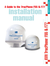
Step One:
Cut a 42mm hole in the position where the antenna needs to
be tted. Put both “Inmarsat” and “GPS” cables though the hole
making sure the nut and washer are on the underside of the hole.
Step Two:
Put the cables though the hole of the bolt mounting plate
as shown below. Make sure that the o-ring is in place at the
base of the hole on the bolt mounting plate.
Connects to IsatDock
Step Three:
Screw the “Inmarsat” cable into the ISAT connector and the
“GPS” cable to the GPS connector on the back of the antenna.
Connects to IsatDock
Step Four:
Slide the bolt mounting plate down onto the back of the
antenna base.
Connects to IsatDock
Step Five:
Using the three large screws (with a split washer and a at
washer on each) in the upper three holes and the 3 small screws
(with a split washer and a at washer on each) in the lower three
holes x the bolt mounting plate to the back of the antenna.
Connects to IsatDock
Step Six:
Set the antenna onto the roof and push the mounting washer
up from the underside. Use mounting nut to secure the antenna
to the roof and tighten. A silicone sealant may need to be put
around the hole to prevent water entering.
Connects to IsatDock
Installation Guidelines
To ensure maximum performance of the antenna system and to
maximise availability and reliability of service the antenna must;
have a clear line of site to the sky
be clear and free of obstructions
be clear of metal objects
be located away from other transmitting devices
be securely axed in location
not be located indoors
be installed in conjunction with a certied cable
Installing Antenna Cables
When installing antenna cables, follow these guidelines:
Route and restrain cables to prevent them from vibrating
or moving under normal conditions, which could result in
damage to the antenna or the coaxial cable connections.
Where ever the cables contact structures, protect the
cables from chang or abrasion. If a cable needs to be
bent, avoid kinking it, and ensure that each bend radius
follows the cable supplier limits.
Use coaxial sealant, shrink‐wrap tubing, electrical tape,
or another suitable product to seal all cable connections
appropriately to prevent moisture and corrosion damage
from weather exposure.
Mount all antennas vertically and clear of nearby metal
obstructions.
Minimize horizontal obstructions as much as possible
because they can create areas of poor system coverage.
Installation Options
The antenna system is suitable for marine, vehicle and
xed applications and is designed to meet Inmarsat System
performance requirements when installed according to the
instructions in this guide.
The following gure shows typical Installations:
The antenna must be installed without obstruction of other
instruments or structures. The antenna must not be positioned
within range of radar equipment or other RF interference.
WARNING
To satisfy FCC RF exposure requirements for mobile transmitting devices, a separation distance of 55 cm or
more should be maintained between the antenna of this device and persons during device operation. To
ensure compliance, operations at closer than this distance is not recommended.
NOTE:
For Satellite & GPS connection instructions please consult your Beam Inmarsat Product manual.
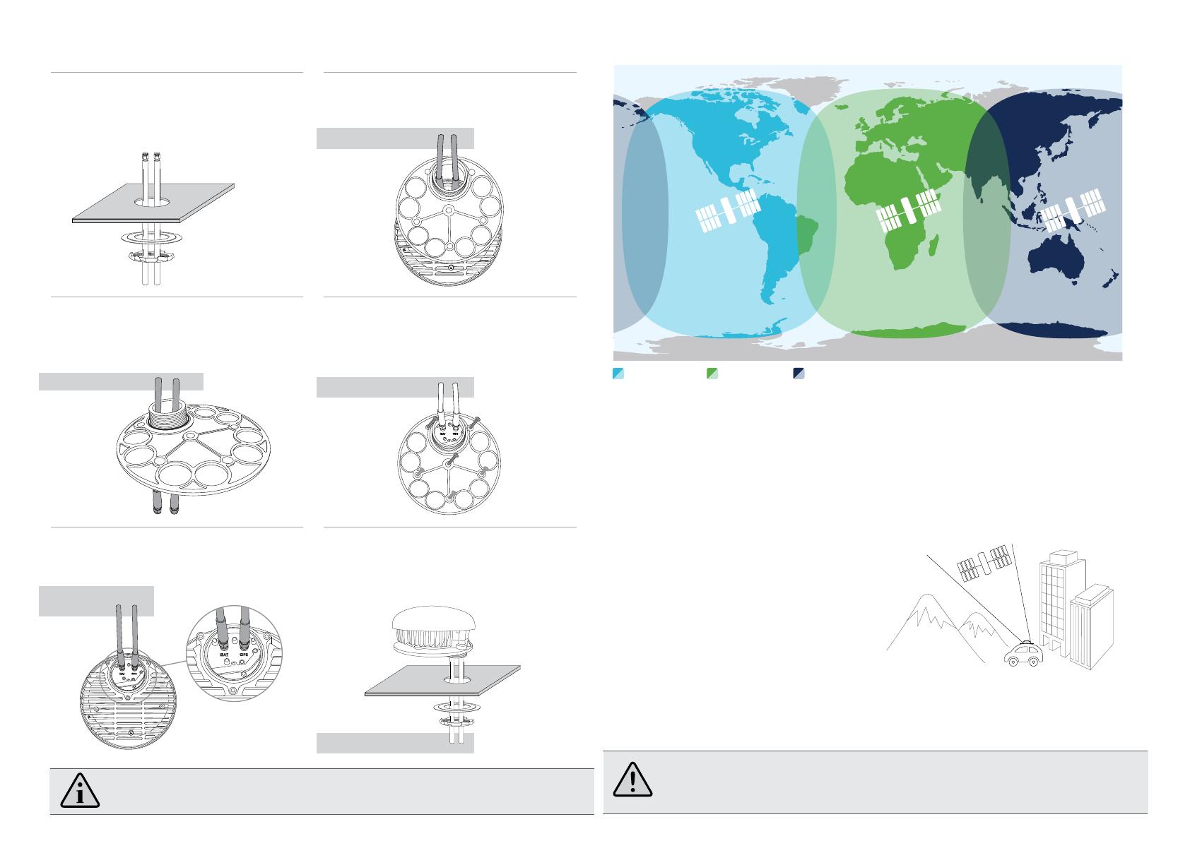
Antenna Coverage
I-4 Americas
I-4 EMEA
I-4 Asia-Pacic
Sourced from Inmarsat
  • Page 1 1
  • Page 2 2

Beam ISD720 Installation guide

Type
Installation guide

Beam ISD720 is a transport bolt antenna designed for marine, vehicle, and fixed applications. It offers clear and reliable communication by providing a stable connection to Inmarsat and GPS networks. The antenna features an integrated amplifier, ensuring optimal signal strength and quality even in challenging conditions. With its durable construction and resistance to harsh environments, Beam ISD720 is a dependable solution for maintaining seamless communication during your travels or operations.

Ask a question and I''ll find the answer in the document

Finding information in a document is now easier with AI