Page is loading ...

1
Maintenance Guide
Operation &B
Installation
SHOWER CONTROL
THESE INSTRUCTIONS ARE TO BE LEFT WITH THE USER

2
CONTENTS
Introduction .............................................................................................3
Description ...............................................................................................3
Safety : Warnings ....................................................................................4
Pack Contents .........................................................................................5
Dimensions ..............................................................................................7
Specication ............................................................................................9
Operating Parameters: Pressures And Flow Rates............................10
Pressures ..........................................................................................10
Flow Rates .........................................................................................10
Temperature Control ...........................................................................10
Plumbing Connections ....................................................................... 11
Installation Requirements .................................................................... 11
Gravity Fed System ............................................................................12
Gas Heated System ...........................................................................12
Unvented Mains Pressure System ..................................................... 13
Mains Pressurised Instantaneous Hot Water System ........................13
Pumped System ................................................................................. 14
Installation .............................................................................................15
Regulators .......................................................................................... 16
Reversing Outlet .................................................................................19
Commissioning .....................................................................................30
Operation ...............................................................................................31
Fault Diagnosis ......................................................................................32
Maintenance ...........................................................................................33
Spare Parts ............................................................................................34
Notes ......................................................................................................39
Customer Services ................................................................................ 40

3
INTRODUCTION
DESCRIPTION
The Mira Mode thermostatic shower valve provides accurate temperature control
and ow rates.
The Mira Mode is available in the following options;
Mira Mode - Surface Mounted
An exposed shower control for connection to rear top and bottom entry pipework.
Refer to Specication for details on the pressure ranges.
Mira Mode - Recessed
A built-in shower control for connection to concealed pipework. Refer to Specication
for details on the pressure ranges.
Thank you for purchasing a quality Mira product. To enjoy the full potential of your
new product, please take time to read this guide thoroughly, having done so, keep
it handy for future reference.
Mira Mode Thermostatic mixing valves are specied to meet the highest standards
of safety, comfort and economy as demanded by todays users.
This Manual covers all Mira Mode Thermostatic Mixing Valves manufactured from
August 2000.
If you experience any difculty with the installation or operation of your new shower
control, then please refer to section ‘Fault Diagnosis’, before contacting Kohler
Plumbing Solutions. Our telephone and fax numbers can be found on the back
cover of this guide.

4
SAFETY : WARNINGS
Mira products are precision-engineered and should give continued superior and
safe performance, provided:
1. They are installed, commissioned, operated and maintained in accordance with
the recommendations given in this Manual.
2. Periodic attention is given, as necessary, to maintain the product in good
functional order.
The function of a thermostatic mixing valve is to deliver water consistently at a safe
temperature.
Provided it is installed, commissioned, operated and maintained within these
recommendations, the risk of failure, if not eliminated, is reduced to the minimum
achievable.
Anyone who may have difculty understanding or operating the controls of any shower
should be attended whilst showering. Particular consideration should be given to
the young, the elderly, the inrm, or anyone inexperienced in the correct operation
of the controls.

5
PACK CONTENTS
Tick the appropriate boxes to familiarize yourself with the part names and to
conrm that the parts are included.
Documentation
1 x Installation, Operation and Maintenance Guide
1 x Customer Support Brochure
1 x Riser Arm
5 x Wall Plugs
1 x Valve
5 x Fixing Screws
2 x Flow Regulators
1 x Shower Rose
1 x Support Brackets
1 x Hexagonal Wrench
Mira Mode
(‘O’Seal Fitted)

6
Tick the appropriate boxes to familiarize yourself with the part names and to
conrm that the parts are included.
Documentation
1 x Installation, Operation and Maintenance Guide
1 x Customer Support Brochure
Mira Mode B
5 x Wall Plugs
1 x Valve
5 x Fixing Screws
1 x Shower Rose
1 x Building-in Shroud
1 x Shower Arm Assembly
(‘O’Seal Fitted)
2 x Panel Screws
1 x Hexagonal Wrench
2 x Flow Regulators

7
All dimensions are nominal and in mm
DIMENSIONS
110 mm
Mira Mode
90 mm max.
203 mm (8”)
435 mm
886 mm 1115 mm

8
All dimensions are nominal and in mm
Mira Mode B
152 mm
411 mm
203 mm (8”)
157 mm
155 mm Dia

9
SPECIFICATION
Important Points:
1. The installation, commissioning and maintenance of this product must be
carried out in accordance with instructions given in this Manual, and must be
conducted by designated, qualied and competent personnel.
2. The plumbing installation must comply with the requirements of UK Water
Regulations/Bye-laws (Scotland), Building Regulations or any particular
regulations and practices, specied by the local water company or water
undertakers. The installation should be carried out by a plumber or contractor
who is registered, or is a member of, an association such as:
• Institute of Plumbing (IOP), throughout the UK.
• National Association of Plumbing, Heating and Mechanical Services
Contractors (NAPH & MSC), England and Wales.
• Scottish and Northern Ireland Plumbing Employers’ Federation (SNIPEF),
Scotland and Northern Ireland.
3. Mira products are precision-engineered and should give continued superior
and safe performance, provided:-
• they are installed, commissioned, operated and maintained in
accordance with these recommendations and
• periodic attention is given as necessary to maintain the product in
good functional order. See Section ‘MAINTENANCE’ for guidelines.
4. Warning: continued use of this product in conditions outside the limits listed
in this section can severely affect the performance and reduce the effective
service life, and can present potential risk to users.
5. Suitable for use with most modulating Instantaneous Gas Water Heaters.
For information on other specic applications or suitability, refer to Kohler Mira
Ltd., or Local Agent.

10
Pressures
For optimum performance, maintained supply pressures should be nominally equal.
Maximum Pressure Loss Ratio: 5:1
Minimum Maintained Pressure (gravity system): 0.1 bar.
(0.1 bar = 1 metre from base of cold tank to outlet of shower tting)
Maximum Maintained Pressure: 6.0 bar
(Note! Flow regulators must be tted above 3.5 bar)
Minimum Maintained Pressure (gas water heater): 1.0 bar.
Maximum Static Pressure: 10 bar.
Flow Regulator Installation
Flow regulators are supplied with this product and should be tted in high pressure
systems to either;
• Reduce excessive force and ow rate.
• Reduce noise through the mixer due to high or unequal pressures.
• Stabilise incoming supply temperatures
Flow Rates
Operating Parameters: Pressures And Flow Rates
Temperature Control
Minimum temperature differential between hot and outlet temperature: 10°C
Optimum temperature control range: 35 - 45°C
Maximum hot water temperature: 85°C (BS 6700 recommends that the temperature
of stored water should never exceed 65°C. A stored water temperature of 60°C is
considered sufcient to meet all normal requirements and will minimise the deposition
of scale in hard water areas).

11
The performance specication outlined below is achieved with outlet blend
temperature set between 35 - 45°C and supplies of 15°C cold and 65°C hot with
nominally equal pressures.
Key to Symbols
Isolating valve
Mixing Valve
Twin Impeller Pump
Tempering Valve
Pressure Reducing Valve
Single Impeller Pump
Overow Indicator
Mini Expansion Vessel
INSTALLATION REQUIREMENTS
• Outlet blend temperature is maintained within 2°C with a
10°C change in hot or cold supply.
• Thermostatic shut down to seepage within 2 seconds if cold supply
fails. This is achieved only if the hot supply temperature is 10°C above
the set outlet blend temperature.
Inlet connectors are 15 mm compression
Outlet connector is 15 mm compression
Hot (H) and Cold (C) inlets are clearly marked and must be connected this way.
Plumbing Connections

12
Gravity Fed System
The shower MUST be fed from a cold water cistern and hot water cylinder providing
nominally equal pressure.
Gas Heated System
The shower MUST be installed with a gas water heater or combination boiler of a
fully modulating design.
A fully modulating boiler is one where the draw off rate is indirectly controlling the
gas ow to the boiler, producing a relatively constant hot water temperature.

13
Mains Pressurised Instantaneous Hot Water System
The shower installed with systems of this type is supplied hot water via a tempering
valve, this provides relatively constant hot water and the shower will compensate
for temperature changes should they occur.
Unvented Mains Pressure System
The shower can be installed with an unvented, stored hot water cylinder. Only
“a competent person” as dened by the Building Regulations may t this type of
system.

14
Pumped System
The shower can be installed with an inlet pump (twin impeller). The pump must be
installed on the oor next to the hot water cylinder. Ensure hot cylinder vent pipe is
arranged as shown to enable air separation.
90°
30°-60°
Air Separation

15
INSTALLATION
General
Installation must be carried out in accordance with these instructions, and must be
conducted by designated, qualied and competent personnel.
1. Before commencing, ensure that the installation conditions comply with the
information given in section ‘SPECIFICATION’.
2. Care must be taken during installation to prevent any risk of injury or damage.
3. The mixing valve should be positioned for easy access during use and
maintenance. All routine maintenance procedures can be conducted with the
mixing valve body in place.
4. Conveniently situated isolating valves must be provided for maintenance.
5. Pipework must be rigidly supported.
6. Pipework dead-legs should be kept to a minimum.
7. Supply pipework layout should be arranged to minimise the effect of other outlet
usage upon the dynamic pressures at the mixing valve inlets.
8. To eliminate pipe debris it is essential that supply pipes are thoroughly
ushed through before connection to the mixing valve.

16
Fitting Regulator
1. Remove compression nut
and olive from inlet elbow or
connector.
2. Ensure ‘o’ seal is tted to ow
regulator and push inside
until ange locates up against
internal shoulder of inlet
elbow/connector.
3. Make compression tting using
compression nut and olive.
Two grey ow regulators are supplied with the product. They t into the cold
and / or hot inlet connectors for high pressure systems.
The selection table indicates when and where these can be tted.
Regulators
Inlet Tube
Compression Nut
Olive
Inlet Elbow/Connector
Incorrect Fitting
‘O’ Seal
Flow
Regulator
Optional Fit only if the force and ow from shower tting is too great
*Required above 3.5 bar maintained.
System Cold Supply Hot Supply
Gravity Fed System
Gas Water Heated System
Optional*
Mains Pressurised
Instantaneous System
Optional*
Unvented Mains Pressure
System
Optional* Optional*
Pumped System Optional* Optional*

17
Mira Mode
Back Inlet Supplies (rising or falling concealed pipework)
1. Decide on a suitable position for
the product ensuring that the mixer
and the shower head is at a height
suitable for all users to operate
(Note! longer riser arms are NOT
available).
2. Remove backplate from rear of
mixer by loosening grub screw
with hexagon key (supplied) on the
underside of mixer.
3. Use the backplate to mark 4 hole
positions. Drill the wall and insert the
wall plugs (4 off, supplied). For other
types of wall structure alternative
xings may be required.
Fit the backplate to the wall using
the xing screws. Ensure TOP on
backplate is positioned correctly.
Backplate
Fixing Screws
Wall Plugs
4. Use a spirit level and pencil to mark
the route of the hot and cold water
supply pipes at 110 mm centres.

18
5. Remove the plaster and brick/block
to the required depth to conceal the
pipework.
Note! Depth must be sufficient to
prevent pipe concealing plates fouling
on the plumbing elbows.
6. Install the supply pipes. The pipes must
be at 110 mm centres and project the
following distances from the nished
wall surface:
18 mm if ow regulators are being tted.
21 mm if no ow regulators are tted.
7. Finish the surface of the wall as
required.
8. Slide the pipe concealing plates with ‘O’
seals tted, nuts and olives over the hot
and cold supply pipes.
9. Thoroughly ush the hot and cold
water supply pipes. The supplies
must be clean and free from debris
before connecting the shower
control. Failure to do so may result
in product malfunction.
Dimension from
nished wall
surface
110 mm
Centres
Concealing Plate
Nut
Olive

19
10. Locate the shower control on to the
supply pipes and hold it in position.
11. Use a suitable spanner to tighten the
nuts and pull the shower control onto
the backplate. Protect the chromium
plated surfaces with a cloth. Use
the 2.5 mm A/F hexagon wrench
(supplied) to tighten the two grub
screw in the backplate. The grub
screw will hold the shower control in
position.
12. With the shower control turned off.
Turn on the water supplies and check
for any leaks.
Shower Control
2.5 mm A/F
Hexagon Wrench
Reversing Outlet
To reverse outlet connector follow
instructions below.
1. Using a suitable tool, remove the
plug cap from the centre of sealing
plug to reveal keyway.
2. Insert a 1/2” hexagon key (not
supplied) into keyway and remove
sealing plug.
3. To remove outlet connector, insert
key and remove as 2.
4. When retting ensure ‘o’ seal is
located in recess of sealing plug
and outlet connector.
Plug Cap
1/2”
Hexagon
Key
Sealing
Plug
‘O’ Seal
Outlet Connector

20
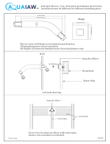
6. Attach the shower rose to the
shower arm and tighten.
Shower Rose
Shower Arm
Support Bracket
Wall Plate
Shower Arm
2.5 mm A/F
Hexagon Wrench
Shower Fittings
1. Temporarily t the shower arm and
the support bracket to the outlet of
the shower control and mark the hole
position. Ensure the support bracket
is tted no more than 90mm below
the top of the shower arm
Note! Use a spirit level or other
device to ensure shower arm is
vertical.
2. Remove the shower arm and support
bracket.
3. Drill the wall and insert a suitable wall
plug (supplied). Fit the wall plate to
the wall.
4. Ret the shower arm and support
bracket. Attach to the support
bracket to the wall plate.
5. Ensure supply pipework is ushed
through before tting shower rose.
90 mm Maximum
/