ENGLISH INSTRUCTIONS
Warranty n
The Seller warrants that the equipment manufactured by it and covered by this
order or contract is free from defects in material and workmanship and, without
charge, equipment found to be defective in material or workmanship will be
repaired, or at Seller’s option replaced F.O.B. original point of shipment, if written
notice of failure is received by Seller within one (1) year after date of shipment
(unless specifically noted elsewhere), provided said equipment has been properly
installed, operated in accordance with the Seller’s instructions, and provided such
defects are not due to abuse or decomposition by chemical or galvanic action.
THIS EXPRESS WARRANTY IS IN LIEU OF AND EXCLUDES ALL OTHER WARRAN-
TIES, GUARANTEES, OR REPRESENTATIONS, EXPRESS OF IMPLIED. THERE ARE
NO IMPLIED WARRANTIES OF MERCHANTABILITY OR OF FITNESS FOR A PAR-
TICULAR PURPOSE. The Seller assumes no responsibility for repairs made on the
Seller’s equipment unless done by the Seller’s authorized personnel, or by written
authority from the Seller. The Seller makes no guarantee with respect to material
not manufactured by it.
Garantía n
El Vendedor garantiza que los equipos fabricados por él y cubiertos por esta orden
o contrato están libres de defectos en los materiales y mano de obra y que los
equipos con materiales o mano de obra defectuosos serán reparados sin cargo
o, a opción del Vendedor, reemplazados F.O.B. en el punto original de envío, si
el Vendedor recibe una notificación por escrito de falla en el lapso de un (1) año
después de la fecha de envío (a menos que se especifique en otra parte), siempre
y cuando dichos equipos hayan sido correctamente instalados y utilizados de
conformidad con las instrucciones del Vendedor, y siempre que dichos defectos
no se deban a maltrato o descomposición por acción química o galvánica. ESTA
GARANTÍA EXPRESA REEMPLAZA Y EXCLUYE CUALQUIER OTRA GARANTÍA,
GARANTÍA GRATUITA O PROMESA, EXPRESAS O IMPLÍCITAS. NO EXISTEN
GARANTÍAS IMPLÍCITAS DE COMERCIALIZACIÓN O DE IDONEIDAD PARA UN
PROPÓSITO EN PARTICULAR. El Vendedor no asume ninguna responsabilidad
por las reparaciones hechas a los equipos del Vendedor salvo que se realicen por
personal autorizado por el Vendedor o con autorización escrita del Vendedor. El
Vendedor no otorga ninguna garantía con respecto a los materiales no fabricados
por él.
Garantie n
Le vendeur garantit que l'équipement fabriqué par lui et couvert en vertu de
cette commande ou de ce contrat est exempt de vices de matériau et de fab-
rication et, dans l'éventualité ou de tels vices de matériau ou de fabrication
se manifesteraient, il sera réparé sans frais ou, à la discrétion du vendeur,
remplacé franco à bord (FAB) de son point d'expédition d'origine (sauf si
spécifié ailleurs), pourvu que ledit équipement ait été installé correctement
et utilisé conformément aux instructions du vendeur et, pourvu que de tels
vices ne soient pas le résultat d’une utilisation abusive ou d'une décom-
position découlant d'une réaction chimique ou galvanique. LA PRÉSENTE
GARANTIE EST EXPRESSE, REMPLACE ET EXCLUT TOUTE AUTRE GARANTIE
OU REPRÉSENTATION EXPRESSE OU IMPLICITE. IL N’EXISTE AUCUNE
GARANTIE TACITE DE QUALITÉ MARCHANDE OU D’ADAPTATION À UN BUT
PARTICULIER. Le vendeur n’assume aucune responsabilité pour des répara-
tions effectuées sur son équipement à moins qu'elles aient été effectuées par
du personnel autorisé par lui ou par une autorisation écrite de lui. Le vendeur
n’offre aucune garantie pour les matériaux non fabriqués par lui.
USA: Phone: 1.800.669.5430 • Fax 1.847. 229.0526 • www.powerscontrols.com
Canada: Phone: 1.888.208.8927 • Fax 1.888. 479.2887 • www.powerscontrols.ca
IS-P-205_215 1314 EDP# 6512326 © 2013 Powers
USA: Phone: 1.800.669.5430 • Fax 1.847. 229.0526 • www.powerscontrols.com
Canada: Phone: 1.888.208.8927 • Fax 1.888. 479.2887 • www.powerscontrols.ca
IS-P-205_215 1314 EDP# 6512326 © 2013 Powers
USA : Phone: 1.800.669.5430 • Fax 1.847. 229.0526 • www.powerscontrols.com
Canada : Phone: 1.888.208.8927 • Fax 1.888. 479.2887 • www.powerscontrols.ca
IS-P-205_215 1314 EDP# 6512326 © 2013 Powers
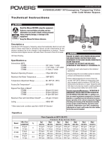
Specifications n
Connections .......................................................... 3/8" compression inlets with
checks
Maximum Operating Pressure .......................... 125psi (861 kPa)
Maximum Hot Water Temperature ................... 194°F (90°C)
Minimum Hot Water Supply Temp. ................... 5°F (3°C) Above Set-Point
Temperature Adjustment Range ....................... 60 - 120°F (15 - 49°C)
Minimum Flow ........................................................ 0.5 gpm (2.2 lpm)
Cold Water Inlet Temperature Range ............... 39 - 80°F (4 - 27°C)
Hot Water Inlet Temperature Range ................. 120 - 180°F (49 - 82°C)
Listing ..................................................................... ASSE 1070, IAPMO cUPC
Approval Standards ............................................. ASSE 1070, CSA B125.3,
NSF 61 Section 9 Annex G
Installation Instructions n
1. Flush all piping thoroughly before installing.
2. The installation and field adjustment of TempTAP
™
faucet is the responsibility of the
installer and shall be carried out in accordance with the following steps.
3. Attach threaded rod to faucet body.
For 3 holes 8" centers (Series 215)
1. Place gasket and threaded rod under the base plate. Place base plate over the hole.
2. Place washer on the threaded rod and tighten with the wing nut. Faucet control should
be on the right.
3. Install washer on the base of the gooseneck spout and secure it with the shank nut on
the center hole.
4. Position faucet body with O-ring on the base plate.
5. Install supply tubes with check valves to hot and cold inlets.
Inlets are marked "H" and "C" underneath the faucet body. Install faucet outlet tube to
body. Make sure O-rings are in place.
WARNING
!
SUPPLY TUBES –HAND TIGHTEN ONLY! Over tightening , using lubricants or exposure to
corrosive materials can damage supply tube threads and cause failure, leaking, or flood
and property damage.
6. Install washer on the threaded rod and tighten with mounting nut.
7. Connect gooseneck spout to faucet body using flexible supply.
8. Connect supply tubes to water supplies.
9. With the handle in "off" position, turn on water supplies and check for leaks.
10. Remove aerator and turn faucet to hot and cold water position to flush the line thoroughly.
Replace aerator.
Troubleshooting n
Faucet Drip
Remove cartridge and clean sealing areas on cartridge and the faucet body.
Reassemble and reset outlet temperature (refer to temperature adjustment section)
Outlet temperature is too hot or too cold
Check temperature limit stop setting (refer to temperature adjustment section)
The flow of water is insufficient or completely shutoff
Check that supply line valves are open. Remove aerator and clean.
Installation Instructions (cont.) n
Part List n
Index Description Part #
1 Handle Kit 4" 105 058
2 Handle Kit 6" 105 059
3 Cartridge Kit 105 060
4 Aerator 2.0 gpm 105 065
5 Base Plate 105 062
6 Faucet Mounting Hardware 105 063
7 Supply Tubes 105 064
TempTAP
™
Thermostatic Faucet with Gooseneck
Grifo termostático con cuello de cisne
Robinet thermostatique avec col de cygne
Technical Instructions
Instrucciones técnicas
Instructions techniques
IS-P-205_215
Min. Flow
to ASSE 1070
C
V
10psi
(69 kPa)
20psi
(138 kPa)
30psi
(207 kPa)
45psi
(310 kPa)
60psi
(414 kPa)
0.5 gpm
1.89 lpm
0.345
1.08 gpm
4.09 lpm
1.53 gpm
5.79 lpm
1.88 gpm
7.12 lpm
2.30 gpm
8.71 lpm
2.60 gpm
9.48 lpm
Capacity Table
*
n
*Less aerator & outlet temperature of 105°F (41°C)
For two holes (Series 205)
1. Install supply tubes with
check valves to hot and
cold inlets. Inlets are
marked "H" and "C" under-
neath the faucet body.
Install faucet outlet tube
to body. Make sure
O-rings are in place.
WARNING
!
SUPPLY TUBES –HAND
TIGHTEN ONLY! Over tighten-
ing , using lubricants or exposure to corrosive materials can damage supply tube threads
and cause failure, leaking, or flood and property damage.
2. Install washer on the base of the gooseneck spout and secure it with the shank nut on the
sink.
3. Position faucet body with O-ring on the sink.
4. Install washer on the threaded rod and tighten with mounting nut.
5. Connect gooseneck spout to faucet body using flexible supply.
6. Connect supply tubes to water supplies.
7. With the handle in "off" position, turn on water supplies and check for leaks.
8. Remove aerator and turn faucet to hot and cold water position to flush the line thoroughly.
Replace aerator.
Temperature Adjustment n
Maximum temperature setting adjustment must be set on the job to no greater than 105°F (41°C).
1. Remove handle by unscrewing set screw with allen wrench provided. Remove shroud.
2. Loosen two high temperature limit stop screws.
3. Replace handle and rotate handle clockwise to desired outlet temperature.
4. Remove handle and slide high temperature limit stop on inner bonnet ring, sliding it coun-
ter clockwise until it contacts cartridge lever.
WARNING
!
Do not exceed temperature above 105°F (41°C).
GOOSENECK SPOUT
SHANK
NUT
WASHER
WING NUT
THREADED ROD
FLEXIBLE SUPPLY
HANDLE
BASE PLATE
AERATOR
FAUCET BODY
THREADED
ROD
WASHER
MOUNTING
NUT
HOT WATER
SUPPLY
GASKET
COLD WATER
SUPPLY
5. Tighten high temperature limit stop screws.
6. Install shroud and handle.
7. Turn handle to maximum hot
position and verify temperature
setting.
Temperature Adjustment (cont.) n
SET SCREW
INNER
BONNET
RING
HANDLE
SHROUD
CARTRIDGE
LEVER
SCREWS
HIGH
TEMPERA-
TURE
LIMIT STOP
Certied to NSF/ANSI 61
Section 9-G
Advanced
Thermal
Activation
1, 2
4
5
7
3
6
FAILURE TO COMPLY WITH PROPER INSTALLATION AND MAINTENANCE
INSTRUCTIONS COULD CONTRIBUTE TO THE VALVE FAILURE, RESULTING IN
INJURY AND/OR DEATH.
TO ENSURE THE ACCURATE AND RELIABLE OPERATION OF THIS PRODUCT, IT
IS ESSENTIAL TO:
• Properlydesignthesystemtominimizepressureandtemperaturevariations.
• Conductanannualmaintenanceprogramtoensureproperoperationofall
critical components.
• Thisvalveisnot factory presetandcan be adjustedtodeliver scalding
temperatures. Check outlet temperature to ensure it does not exceed 105°F
(41°C). Make sure temperature limit stop is properly re-set to maximum
105°F (41°C) following valve maintenance or repair. Tampering with limit stop
in any way may result in scalding temperature causing serious bodily harm
and/or death.
WARNING
WARNING
!
WARNING
!
Read this Manual BEFORE using this equipment.
Failure to read and follow all safety and use information can result
in death, serious personal injury, property damage, or damage to the
equipment.
Keep this Manual for future reference.
WARNING: This product contains chemicals known to the
State of California to cause cancer and birth defects or other
reproductive harm.
For more information: www.watts.com/prop65
ADVERTENCIA: Este producto contiene sustancias químicas
que en el Estado de California se conocen como causantes
de cáncer y malformaciones u otros daños reproductivos.
Para más información: www.watts.com/prop65
AVERTISSEMENT: Ce produit contient des produits chi-
miques reconnus par l’État de Californie comme étant can-
cérigènes et pouvant provoquer des anomalies congénitales
ou affecter la capacité de reproduction.
Pour plus d'informations: www.watts.com/prop65
WARNING
!
Need for Periodic Inspection: Periodic inspection by a licensed contractor
is recommended. Corrosive water conditions, and/or unauthorized adjust-
ments or repair could render the valve ineffective for service intended.
Regular checking and cleaning of the valve’s internal components and
check stops helps assure maximum life and proper product function.
Frequency of cleaning and inspection depends upon local water conditions.