
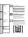
Room Air Conditioner
(Window Type)
OWNER'S MANUAL

Operating instructions
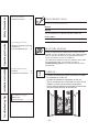
About the Controls on the Air
Conditioner .........................5
Care and Maintenance .......8
Installation Instructions
Features...............................9
Installation Instructions.........9
Troubleshooting tips
Before You
Call for Service..................11
Safety precautions
Safety Precautions .............3
FOR YOUR RECORDS
Write the model and serial numbers here:
Model #
Serial #
You can find them on a label on the side of each unit.
Dealer's Name
Date Purchased
READ THIS MANUAL
Inside you will find many helpful hints on how to use and
maintain your air conditioner properly. Just a little preventive
care on your part can save you a great deal of time and
money over the life of your air conditioner.
You'll find many answers to common problems in the chart
of troubleshooting tips. If you review our chart of
Troubleshooting Tips first, you may not need to call for
service at all.
CAUTION
Contact the authorized service technician for repair
or maintenance of this unit.
Contact the installer for installation of this unit.
The air conditioner is not intended for use by young
children or infirm persons without supervision.
Young children should be supervised to ensure that
they do not play with the air conditioner.
-2-
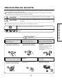
Safety Precautions
Operating Instructions
Installation Instructions
Troubleshooting Tips

Safety Precautions
Safety Precautions
To prevent injury to the user or other people and property damage, the following instructions must be
followed.
Incorrect operation due to ignoring of instruction will cause harm or damage, the seriousness is classified
by the following indications.
WARNING
CAUTION
:
:
This symbol shows the possibility of causing death or serious injury.
This symbol indicates the possibility of injury or damage to
properties only.
The items to be followed are classified by the following symbols.
Never Do This
Always Do This
WARNING
Plug in the power plug
properly.
Do not operate or stop the
unit by inserting or pulling
out the power plug.
Do not damage or use an
unspecified power cord.
Otherwise, it will c ause electric
shock or fire due to heat
generation or electrical shock.
It will c ause electrical shock or
fire due to heat generation.
It will cause electrical shock or fire.
If the supply cord is damaged, it
must be replaced by a special cord
or assembly available from the
manufacturer or its service agent.
Do not modify power cord
length or share the outlet
with other appliances.
Do not operate with wet
hands or in damp
environment.
Do not direct airflow at room
occupants only.
It will c ause electrical shock or
fire due to heat generation.
It may cause electric al shock.
This could damage your health.
-3-

Never touch the metal parts
of the unit when removing
the filter.
Do not clean the air
conditioner with water.
Ventilate well when used
together with a stive, etc.
It may cause an injury.
When cleaning the unit, first
make sure the power and
breaker are turned off.
Do not put a pet or house
plant where it will be
exposed to direct air flow.
Do not use for special
purposes.
Since the fan rotates at high
speed during operation, it may
cause an injury.
CAUTION
Water may enter the unit and
degrade the insulation. It may
cause an electric shock.
An oxygen shortage may occur.
This could injure the pet or plant. Do not use this air conditio ner to
preserve precision devices, food,
pets, plants, and art objects.
It may cause deterioration of
quality, etc.
Do not operate Switches
with wet hands.
Do not apply an insecticide
or flammable spray.
Do not put a heater, etc.
where is exposed to direct air
flow.
It may cause an electric shock. It may cause a fire or deformation
of the cabinet.
It may cause imperfect
combustion.
Safety Precautions
-4-

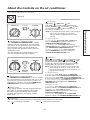
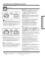
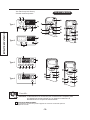
About the Controls on the air conditioner
The controls will look like the following.
Controls
THERMOSTAT (TEMPERATURE)
The THERMOSTAT/TEMPERATURE is used to
maintain the room temperature. The compressor
will cycle on and off to keep the room at the same
level of comfort. When you turn the knob to a
higher number (the right side) and the indoor air
will become cooler.
The 5 or 6 position (the middle position of arc)
is a normal setting for average conditions.
THERMOSTAT (TEMPERATURE)
The THERMOSTAT/TEMPERATURE is used to maintain
the room temperature. The compressor will cycle on and
off to keep the room at the same level of comfort. The
temperature is selected by turning the THERMOSTAT/
TEMPERATURE knob to the desired position.
HEATER LAMP
At the heating operation, the lamp is lighted. When the
frost settles on the heat exchanger of the outside,
defrosting is made automatically and the lamp is
unlighted. After defrosting, the heating operation
begins again.
AUTO SWING
Auto swing switch controls the horizontal air direction by air swing system (not on all models).
ON Auto swing is operated. OFF Auto swing is not operated.( ) :
( ) :
OPERATION
High Cool ( ), Med Cool ( ) and
Low Cool
( ) provide cooling with different fan
speeds.
Med Fan
( ) or Low Fan ( ) provides
air circulation and filtering without cooling. Off ( O )
turns the air conditioner off.
NOTE:
If you move the switch from a cool setting to
off or to a fan setting, wait at least 3
minutes before switching back to a cool
setting.
Cooling Descriptions
For Normal Cooling- Select High Cool or Med Cool
with the OPERATION knob at the midpoint of
THERMOSTAT/TEMPERATURE knob.
For Maximum Cooling- Select High Cool with the
OPERATION knob at the highest number available on
your THERMOSTAT/TEMPERARURE knob.
For Quieter & Nighttime Cooling- Select Low Cool
with the OPERATION knob at the midpoint of
THERMOSTAT/TEMPERATURE knob.
OPERATION
HIGH ( ) Cool, LOW ( ) Cool provide cooling with
different fan speeds. HIGH ( )heat, LOW( ) heat
provide heating with different fan speeds. FAN ( )
provides air circulation and filtering without cooling or
heating. OFF ( O ) turns the air conditioner off.
NOTE:
If you move the switch from the cool(or the
heat) setting to off or to a fan setting, wait
at least 3 minutes before switching back to a
cool (or heat) setting.
Cooling Descriptions
For Normal Cooling- Select HIGH Cool with the OPERATION
knob at the midpoint of the THERMOSTAT/TEMPERATURE knob.
For Maximum Cooling- Select HIGH Cool with the OPERATION knob
at the clockwise available on the THERMOSTAT/TEMPERATURE knob.
For Quieter & Nighttime Cooling- Select LOW Cool with the
OPERATION knob at the midpoint of the THERMOSTAT/
TEMPERATURE knob.
Heating Descriptions
For Normal Heating- Select HIGH heat with the OPERATION
knob at the midpoint of the THERMOSTAT/TEMPERATURE knob.
For Maximum Heating- Select HIGH heat with the
OPERATION knob at the counterclockwise available on the
THERMOSTAT/TEMPERATURE knob.
For Quieter Heating- Select LOW heat with the OPERATION
knob at the midpoint of the THERMOSTAT/TEMPERATURE knob.
0
TEMPERATURE OPERATION
AUTO SWING
Wait for 3 minutes before restart
Operating Instructions
-5-

Operating Instructions
-6-
5
3
6
2
4
1
22
2 3
4 5 6
1
7
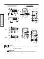
Mode Timer
Fan Speed Temp Auto Swing Power
Fan Cod On
Dry Energy Saver
Type 3
Type 4
Your Panel may look like any
of below mentioned panels.
REMOTE CONTROLLER
Type 2
3
5
6
2
4
1
DOWN UP
POWER
FAN SPEED
TIMER COOLING/FAN
ENERGY SAVERAUTO SWING
( )
2 b
V
V
n
Fa S
pee
d
S p
e
el
Mo
d
e
T
r
m
e
i
oA
tu
S
g
w ni
iA
r
efi
u i
rP r
P e
ow r
1
4
2
63
9
8
5
V
V
a
nF S
pee
d
pS
ele
M
od
e
imeT
r
u oA
t
g
Sw
in
o er
wP
1
4
2
63
9
5
22
5
1
Temp Power
Fan
Cool
Timer
V
V
7
Mode Timer
COOL
DRY
FAN
TEMP
8 8
ENERGY SAVER ON
FAN
SPEED
AUTO
SWING
ON/OFF
(e)
E N E RG Y S AVER
5
Temp
42
7
3 6 1
COOL
FAN
TEMP
8 8
ON/OFF
5
Temp
1
7
Type 1
Controls
The Remote Control unit will not function properly if strong light strikes the sensor
window of the air conditioner or if there are obstacles between the Remote Control
unit and the air conditioner.
Precaution:
POWER BUTTON
Operation starts, when this button is pressed and stops when you press the button again.
1
8

OPERATION MODE SELECTION BUTTON
Select Cooling Fan or Dehumidification (Dry) mode with this button.
ON/OFF TIMER/SLEEP BUTTON
Set the time of on/off operation. The timer can be set by the one hour for a maximum of 12 hours. In the
first 30 minutes set temperature increases by 1°C and in the next 30 minutes temperature increases by
another 1°C, this temperature then remains till the timer function is activated. This is how the sleep
function behaves.
FAN SPEED SELECTOR
Select the fan speed in Three steps Low (F1) / Med. (F2) / High (F3)
ROOM TEMPERATURE SETTING BUTTON
Control the room temperature within a range of 16°C to 30°C.
AUTO SWING
The vertical louver swings horizontally by the automatic system and stops when you press the
button again.
SIGNAL RECEIVER
The fan stops when the compressor stops cooling. Approximately even 3 minutes
ENERGY SAVER
the fan will turn on and check the room air to determine if cooling is needed.
AUTO RESTART
In failure of electric power the unit runs as previous setting operation
when power returns.
2
3
4
5
6
7
8
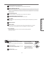
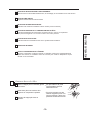
How to Insert the Batteries
Remove the cover from the back of the remote
controller.
Slide the cover according to the arrow direction.
Insert the two batteries.
Be sure that the (+) and (-) directions are correct.
Be sure that both batteries are new.
Re-attach the cover.
Slide it back into the position.
Do not use rechargeable
batteries, such batteries differ
from standard dry cells in shape,
dimensions, and performance.
Remove the batteries from the
remote controller if the air
conditioner is not going to be
used for an extended length of
time.
1
2
3
Operating Instructions
-7-

CLOSE VENT OPEN
Additional controls and important information.
Vent Control
The vent control is located above the
control knobs.
When set at CLOSE, only the air inside
the room will be circulated and
conditioned. When set at OPEN, some
inside air is exhausted outside.
To open the vent, pull the lever toward you.
To close it, push it in.
Air Direction
The direction of air can be controlled
horizontally or vertically by using the
horizontal louver or vertical louver.
The horizontal air direction is adjusted
by setting the AUTO SWING switch to
the ON position.
Horizontal Air-Direction
Vertical Air-Direction
Fingertip pressure on the bank of horizontal
louvers adjusts the air direction up or down
-8-
Operating Instructions

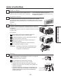
CABINET
DRAIN
PAN
SCREW
DRAIN HOSE
(Optional)
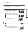
Grille and Case
Turn the air conditioner off and remove the plug
from the wall outlet before cleaning.
To clean, use water and a mild detergent. Do not
use bleach or abrasives.
Air Filter
Ensure the power is off before open the front Grill.
The air filter behind the front grille should be checked and cleaned
at least once every 2 weeks or more often if necessary.
The grille is designed to clean the filter both upward and
downward.
To remove:
Open the inlet grille upward by pulling out the bottom of the
inlet grille or downward by pulling out the top of the inlet grille.
Using the tab, pull up slightly on the filter to release it and pull
it down or up.
Clean the filter with warm, soapy water below 40°C (104°/F).
Rinse and gently shake the water from the filter and let it dry
before replacing it.
CAUTION:
DO NOT operate the air conditioner without a filter
because dirt and lint will clog it and reduce
performance.
Drainage
In humid weather, excess water may cause the BASE PAN to overflow.
To drain the water, remove the DRAIN CAP and secure the DRAIN PIPE
to the rear hole of the BASE PAN.
To remove the condensed water, you can install the drain pan as below.
Take the drain pan which is located in the air discharge.
Install the drain pan to the right corner of the cabinet with 4 screws.
Connect the drain hose to the outlet located at the bottom of the drain
pan. You can purchase the drain hose or tubing locally to satisfy your
particular needs. (Drain hose is not supplied).
1.
2.
3.
Care and Maintenance
-9-
1
2
3
4
1
2
DRAIN CAP
BASE
PAN
(Optional)
Operating Instructions

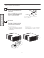
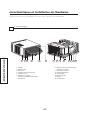
Shipping screws
AWNING
FENCE
HEAT
RADIATION
COOLED
AIR
70-150cm
10~15mm
Over 50cm
1/4 Bubble
Level
7
8
9
10
11 12
13
14
2 31 4 5
6
Features
Features
CABINET
FRONT GRILLE
AIR FILTER
AIR INTAKE(INLET GRILLE)
AIR DISCHARGE
Learning parts name prior to installation will help you understanding the installation procedure.
1.
2.
3.
4.
5.
VERTICAL AIR DEFLECTOR
(HORIZONTAL LOUVER)
6.
EVAPORATOR
7.
HORIZONTAL AIR
DEFLECTOR
(VERTICAL LOUVER)
8.
CONTROL BOARD
POWER CORD
COMPRESSOR
BASE PAN
BRACE
CONDENSER
9.
10.
11.
12.
13.
14.
Installation Instructions
Select the Best Location
To prevent vibration and noise, make sure the unit is
installed securely and firmly.
Install the unit where the sunlight does not shine directly
on the unit.
There should be no obstacle, such as a
fence or wall, within 50cm from the back of the cabinet
because it will prevent heat radiation of the condenser.
Restriction of outside air will greatly reduce the cooling
efficiency of the air conditioner.
Install the unit a little obliquely outward not to leak the
condensed water into the room (about 10 ~ 15mm or 1/4
bubble with level).
CAUTION:
All side louvers of the cabinet must remain
exposed to the outside of the structure.
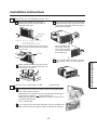
Remove the Air Conditioner From the Case
Remove the 2 shipping screws from the
back of the case.
Remove the 2 screws on each side of the
case. Keep these for later use.
Slide the air conditioner from the case by
gripping the base pan handle and pulling
forward while bracing the case.
Installation Instructions
-10-
A
B
C
D
A
B
C

The Foam
Power Cord
Screw
Screw
Installation Instructions
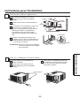
Install the Air Conditioner in the Case
Slide the air conditioner into the case.
Reinstall the screws removed earlier on
each side of the case.
CAUTION:
The power cord must be connected to
an independent circuit.
The green wire must be grounded.
Stuff the foam between the unit and the
wall to prevent air and insects from getting
into the room.
Before installing the front grille, pull out the
vent control lever located above the unit
control knobs, as shown.
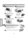
Use the Reversible Inlet Grille
(Optional)
If you want to pull out the filter upward, open the inlet grille slightly.
Turn inside out the front grille.
Disassemble the inlet grille from the front grille with separating the
hinged part by inserting a " " type screw-driver tip.
Rotate the inlet grille 180 degrees and insert the hooks into the
lower holes of front grille.
Then, insert the filter
If you want to pull out the filter downward, use the reversible inlet
grille without change.(The grille is already assembled for that way.)
Attac h the fron t gri lle to the ca se by
inserting the tabs on the grille into the slots
on the front of the case. Push the grille in
until it snaps into place.
When you detach the
fro nt gril le fro m the
case, push the grille
to your right side and
pull it toward you.
Lift the inlet grill and secure the front grille
with a screw. Lower the inlet grille into
place.
A
B
C
D
E
A
B
Installation Instructions
B
-11-

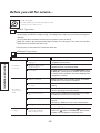
Before you call for service...
Troubleshooting Tips
Save time and money! Review the chart below first and
you may not need to call for service.
Normal Operation
You may hear a pinging noise caused by water being picked up and thrown against the condenser
on rainy days or when the humidity is high. This design feature helps remove moisture and improve
efficiency.
You may hear the thermostat click when the compressor cycles on and off.
Water will collect in the base pan during high numidity or on rainy days. The water may overflow
and drip from the outdoor side of the unit.
The fan may run even when the compressor does not.
Abnormal Operation
Problem
Air conditioner
does not start
The air conditioner is
unplugged.
The fuse is blown/circuit
breaker is tripped.
Power failure.
Air conditioner
does not cool as it
should
Airflow is restricted.
THERMOSTAT control set
too warm.
The air filter is dirty.
The room may have been
hot.
Cold air is escaping.
Cooling coils have iced up.
Air conditioner
freezing up
Ice blocks the air flow and
stops the air conditioner
from cooling the room.
Make sure the air conditioner plug is pushed
completely into the outlet.
Check the house fuse/circuit breaker box and
replace the fuse or reset the breaker.
If power failure occurs, turn the OPERATION control
to OFF( O ) . When power is restored, wait 3 minutes
to restart the air conditioner to prevent tripping of the
compressor overload.
Make sure there are no curtains, blinds, or furniture
blocking the front of the air conditioner.
Turn the THERMOSTAT knob clockwise to a cooler
setting.
Clean the filter at least every 2 weeks.
See the operating instructions section.
When the air conditioner is first turned on you need
to allow time for the room to cool down.
Check for open furnace floor registers and cold air
returns.
Set the air conditioner's vent to the closed position.
See Air Conditioner Freezing Up below.
Set the OPERATION control at fan ( ) or
HIGH cool ( ) with the THERMOSTAT at the warmer
position or the temperature at more than 23°C.
Installation Instructions
-12-
Possible Causes
What To Do
Page is loading ...
Page is loading ...
Page is loading ...
Page is loading ...
Page is loading ...

Type 3
Type 4
V
V
n F
a Spe
e
d
S
p
ee
l
M
o
de
T rmei
o
A
tu
S gw
n
i
iA r
e
fu
i
i
P
r r
P
eo
w
r
1
4
2
63
9
8
5
V
V
aF n
p
e
S ed
e
pS
el
Mode
m
eTi
r
oAu
t
g
S
w
in
o e
r
wP
1
4
2
63
9
5
Mode Timer
COOL
DRY
FAN
TEMP
8 8
ENERGY SAVER ON
FAN
SPEED
AUTO
SWING
ON/OFF
(e)
E N E RG Y S AVER
5
Temp
42
7
3 6 1
COOL
FAN
TEMP
8 8
ON/OFF
5
Temp
1
7
INSTRUCTIONS D'UTILISATION
Contrôles
La télécommande ne fonctionnera pas correctement si le récepteur (situé
su l'appareil) est fortement éclairé ou si un obstacle est situé entre la
télécommande et le récepteur de télécommande.
Précaution:
BOUTON DE MARCHE/ARRET
Les opérations commencent quand on appuie sur ce bouton et s'arrítent quand on
appuie de nouveau.
-18-
TÉLÉCOMMANDE
1
Your Panel may look like any
of below mentioned panels.
5
3
6
2
4
1
22
2 3
4 5 6
1
7
Mode Timer
Fan Speed Temp Auto Swing Power
Fan Cod On
Dry Energy Saver
Type 2
22
5
1
Temp Power
Fan
Cool
Timer
V
V
3
5
6
2
4
1
DOWN UP
POWER
FAN SPEED
TIMER COOLING/FAN
ENERGY SAVERAUTO SWING
( )
2 b
7
Type 1
8
Page is loading ...
Page is loading ...
Page is loading ...
Page is loading ...
Page is loading ...
Page is loading ...
Page is loading ...
Page is loading ...
Page is loading ...
Page is loading ...
-
 1
1
-
 2
2
-
 3
3
-
 4
4
-
 5
5
-
 6
6
-
 7
7
-
 8
8
-
 9
9
-
 10
10
-
 11
11
-
 12
12
-
 13
13
-
 14
14
-
 15
15
-
 16
16
-
 17
17
-
 18
18
-
 19
19
-
 20
20
-
 21
21
-
 22
22
-
 23
23
-
 24
24
-
 25
25
-
 26
26
-
 27
27
-
 28
28


Ask a question and I''ll find the answer in the document
Finding information in a document is now easier with AI
in other languages
- français: LG LW-N2465CIG Manuel utilisateur
Related papers
-
LG LW-C1262BC Owner's manual
-
-
-
LG LW-N1861BCG******* User manual
-
-
-
-
-
-
Other documents
-
Friedrich P/N9362292054 User manual
-
-
-
-
-
Hitachi RAF-25FX8 User manual
-
-
 Zenith Air SMC Operating instructions
-
-
