
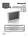
LCD TV
Operating Instructions
TQBC0543
Before connecting, operating or adjusting this product, please read these instructions completely.
Please keep this manual for future reference.
English
Model No.
TC-14LA1
TC-17LA1
TC-20LA1
For assistance, please call : 1-800-211-PANA (7262)
or send e-mail to : [email protected]
or visit us at www.panasonic.com (U.S.A)
For assistance, please call : 787-750-4300
or visit us at www.panasonic.com (Puerto Rico)
For assistance, please call : 1-800-561-5505
or visit us at www.panasonic.ca (Canada)

2
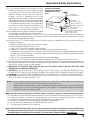
Important Safety Instructions
CAUTION
RISK OF ELECTRIC SHOCK
DO NOT OPEN
The exclamation point within a
triangle is intended to tell the
user that important operating
and servicing instructions are in
the papers with the appliance.
■ Note to CATV System Installer: This reminder is provided to direct the CATV system installer’s
attention to Article 820–40 of the NEC that provides guidelines for proper grounding and, in particular,
specifies that the cable ground shall be connected to the grounding system of the building, as close to the
point of cable entry as practical.
■ Important Safety Instructions for LCD TV
1) Read these instructions and apply them with your LCD TV.
2) Keep these instructions.
3) Heed all warnings.
4) Follow all instructions.
5) Do not use this apparatus near water. For example: Avoid placing it near a bathtub, washbowl, kitchen
sink, or laundry tub, in a wet basement, or near a swimming pool, etc.
6) Clean only with dry cloth. Unplug this LCD TV from the wall outlet before cleaning. Do not use liquid or
aerosol cleaners.
7) Do not block any ventilation openings. Install in accordance with the manufacturer's instructions.
Slots and openings in the cabinet and the back or bottom are provided for ventilation, and to ensure
reliable operation of the LCD TV and to protect it from overheating. These openings must not be blocked
or covered. There should be at least 10 cm of space from these openings. The openings should never
be blocked by placing the LCD TV on a bed, sofa, rug or other similar surface. This LCD TV should not
be placed in a built-in installation such as a bookcase unless proper ventilation is provided.
8) Do not install near any heat sources such as radiators, heat registers, stoves, or other apparatus
(including amplifiers) that produce heat.
9) Protect the power cord from being walked on or pinched particularly at plugs, convenience receptacles,
and the point where they exit from the apparatus.
10)
Only use attachments/accessories specified by the manufacturer. Otherwise it may cause hazards.
11) Use only with the cart, stand, tripod, bracket, or table specified by the manufacturer, or sold
with the apparatus. When a cart is used, use caution when moving the cart/apparatus
combination to avoid injury from tip-over.
12) Unplug this apparatus during lightning storms or when unused for long periods of time. This will prevent
damage to the receiver due to lightning and power-line surges.
13) Refer all servicing to qualified service personnel. Servicing is required when the apparatus has been
damaged in any way, such as power-supply cord or plug is damaged, liquid has been spilled or objects
have fallen into the apparatus, the apparatus has been exposed to rain or moisture, does not operate
normally, or has been dropped.
Upon completion of any service or repairs to this LCD TV, ask the service technician to perform routine
safety checks to determine that the television is in safe operating condition.
14) Operate only from the type of power source indicated on the marking label. If you are not sure of the
type of power supplied to your home consult your television dealer or local power company.
15) Follow all warnings and instructions marked on the LCD TV.
16) Never push objects of any kind into this LCD TV through cabinet slots as they may touch dangerous voltage
points or short out parts that could result in a fire or electric shock. Never spill liquid of any kind on the LCD TV.
The lightning flash with arrow
head within a triangle is intended
to tell the user that parts inside
the product are a risk of electric
shock to persons.

3
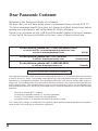
17) If an outside antenna is connected to the
television
equipment, be sure the antenna system
is grounded so as to provide some protection
against voltage surges and built up static
charges. In the U.S. Selection 810-21 of the
National Electrical Code provides information
with respect to proper grounding of the mast and
supporting structure, grounding of the lead-in wire
to an antenna discharge unit, size of grounding
conductors, location of antenna discharge unit,
connection to grounding electrodes, and
requirements for the grounding electrode.
18) An outside antenna system should not be located
in the vicinity of overhead power lines or other
electric light or power circuits, or where it can fall into such power lines or circuits. When installing an
outside antenna system extreme care should be taken to keep from touching such power lines or circuits
as contact with them might be fatal.
19) Unplug this LCD TV from the wall outlet, and refer servicing to qualified service personnel under the
following conditions:
a. When the power cord or plug is damaged or frayed.
b. If liquid has been spilled into the LCD TV.
c. If the LCD TV has been exposed to rain or water.
d. If the LCD TV does not operate normally by following the operating instructions.
Adjust only those controls that are covered by the operating instructions as improper adjustment of other
controls may result in damage and will often require extensive work by a qualified technician to restore
the LCD TV to normal operation.
e. If the LCD TV has been dropped or the cabinet has been damaged.
f. When the LCD TV exhibits a distinct change in performance - this indicates a need for service.
20) When replacement parts are required, be sure the service technician to use replacement parts specified by
the manufacturer that have the same characteristics as the original part. Unauthorized substitutions may
result in fire, electric shock, or other hazards.
21) WARNING: TO REDUCE THE RISK OF FIRE OR ELECTRIC SHOCK, DO NOT EXPOSE THIS
APPARATUS TO RAIN OR MOISTURE.
22) CAUTION: TO PREVENT ELECTRIC SHOCK DO NOT USE THIS PLUG WITH A RECEPTACLE OR
OTHER OUTLET UNLESS THE BLADES CAN BE FULLY INSERTED TO PREVENT BLADE EXPOSURE.
23) CAUTION: USE WITH OTHER STAND MAY RESULT IN INSTABILITY CAUSING POSSIBLE INJURY.
24) CAUTION: DANGER OF EXPLOSION IF BATTERY IS INCORRECTLY REPLACED. REPLACE ONLY
WITH THE SAME OR EQUIVALENT TYPE.
Important Safety Instructions
EXAMPLE OF ANTENNA
GROUNDING AS PER (NEC)
NATIONAL ELECTRICAL
CODE
GROUND
CLAMP
ANTENNA
LEAD-IN WIRE
ANTENNA
DISCHARGE UNIT
(NEC SECTION 810-20)
GROUNDING CONDUCTORS
(NEC SECTION 810-21)
GROUND CLAMPS
POWER SERVICE GROUNDING
ELECTRODE SYSTEM
(NEC ART 250, PART H)
ELECTRIC
SERVICE
EQUIPMENT
■
Important Information Regarding Use of Video Games, Computers, Captions or Other Fixed Image Displays.
The extended use of fixed image program material can cause a permanent "shadow image" on the LCD panel.
This background image is viewable on normal programs in the form of a stationary fixed image. This type of
irreversible LCD panel deterioration can be limited by observing the following steps:
A. Reduce the brightness/contrast setting to a minimum viewing level.
B. Do not display the fixed image for extended periods of time.
C. Turn the power off when not in actual use.
■
This product utilizes tin-lead solder, and has a fluorescent lamp containing a small amount of mercury. Disposal of
these materials may be regulated in your community due to environmental considerations. For disposal or recycling
information please contact your local authorities, or the Electronics Industries Alliance:
www.eiae.org.
NOTE:
•
This equipment is designed to operate in the U.S.A. and other countries where the broadcasting
system and AC house current is exactly the same as in the U.S.A.
•
The marking or retained image on the LCD panel resulting from fixed image use is not an operating
defect and as such is not covered by Warranty. This product is not designed to display fixed image
patterns for extended periods of time.

4
Dear Panasonic Customer
Welcome to the Panasonic family of customers.
We hope that you will have many years of enjoyment from your new LCD TV.
To obtain maximum benefit from your set, please read these instructions before
making any adjustments, and retain them for future reference.
Retain your purchase receipt, and record the model number and serial number
of your set in the space provided on the rear cover of these instructions.
This equipment has been tested and found to comply with the limits for a TV Broadcast Receiver, pursuant
to Part 15 of the FCC Rules. These limits are designed to provide reasonable protection against harmful
interference in a residential installation. This equipment generates, uses and can radiate radio frequency
energy and, if not installed and used in accordance with the instructions, may cause harmful interference to
radio communications. If this equipment does cause or receive interference, which can be determined by
turning equipment off and on, the user is encouraged to try to correct the interference by one of the following
measures:
Reorient or relocate the TV antenna.
Increase the separation between TV and other equipment.
Connect TV into separate outlet from other equipment.
Consult the dealer or an experienced radio/TV technician for help.
FCC Caution: Any changes or modifications not expressly approved by the party responsible for compliance
could void the user’s authority to operate this equipment.
For assistance, please call : 1-800-211-PANA (7262)
or send e-mail to : [email protected]
or visit us at www.panasonic.com (U.S.A)
For assistance, please call : 787-750-4300
or visit us at www.panasonic.com (Puerto Rico)
For assistance, please call : 1-800-561-5505
or visit us at www.panasonic.ca (Canada)
Federal Communication Commission Information

5
Table of Contents
Important Safety Instructions .............................. 2
Table of Contents .................................................. 5
Installation ............................................................. 6
SUPPLIED ACCESSORIES ................................ 6
Remote control battery installation ...................... 7
Maintenance .......................................................... 7
Connections .......................................................... 8
Connecting the Antenna Cable to the Antenna Terminal ....
8
Antenna cover removal and fitting ....................... 8
Antenna / Cable Connection................................ 8
How to connect the input terminals ................... 10
Cable cover removal and fitting ......................... 12
Connecting Headphones / Earphones............... 12
Power ON / OFF................................................... 13
Connecting the Plug to the Wall Outlet.............. 13
How to Turn the Power On ................................ 13
Playing a VCR or other peripheral equipment ... 14
Basic Controls..................................................... 15
Flow Chart of MENU............................................ 16
Tuning channels
(Automatic channel programming) .................. 18
Tuning channels
(Manual channel programming)........................ 19
Picture Adjustments ........................................... 20
Audio Adjustments ............................................. 21
Lock Feature........................................................ 22
Closed Captions.................................................. 26
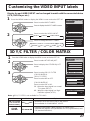
Customizing the VIDEO INPUT labels ............... 27
3D Y/C FILTER / COLOR MATRIX ....................... 27
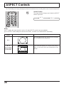
ASPECT Controls................................................ 28
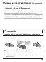
Manual de instrucciones [ Resumen ]
Preparación ...................................................29
Instalación de las pilas del mando a distancia .....
29
Conexión del cable de antena al terminal
de entrada de RF............................................30
Conexión de antena / cable ............................30
Para quitar y colocar la cubierta del cable......30
Conexión de auriculares .................................30
Conexión/desconexión de la alimentación ....
31
Conexión de la clavija a la toma de corriente.....
31
Cómo conectar la alimentación ......................31
Reproducción en una videograbadora o en
otro equipo periférico ...................................32
Controles básicos.........................................33
Organigrama de menús de televisión.........34
Sintonización de canales
(Programación automática de canales).....36
Sintonización de canales
(Programación manual de canales) ............37
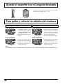
Ajuste el soporte con el ángulo deseado...38
Para quitar y colocar la cubierta de la antena ...
38
Troubleshooting .................................................. 39
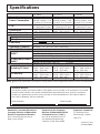
Specifications...................................................... 40

6
Installation
Receiver Location
Locate for comfortable viewing. Avoid placing where sunlight or other bright light (including reflections) will fall on the screen.
Use of some types of fluorescent lighting can reduce remote control transmitter range.
Adequate ventilation is essential to prevent internal component failure. Keep away from areas of excessive heat or moisture.
Optional External Equipment
The Video/Audio connection between components can be made with shielded video and audio cables. For
best performance, Antenna cables should utilize 75 ohm coaxial shielded wire. Cables are available from
your dealer or electronic supply store.
Before you purchase any cables, be sure you know what type of output and input connectors your various
components require. Also determine the length of cable you’ll need.
For optimum quality picture
When the LCD is exposed to light from outdoors or lighting fixtures, high-contrast pictures may not be displayed
clearly. Turn off florescent lamps near the LCD and place in a location not exposed to outdoor light.
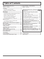
How to use the LCD stand
Adjust the stand to your desired angle. The stand angle can be adjusted between 5 ° forward to 15 ° back.
T
H
-
1
4
L
A
1
Check the accessories before installations.
•
Operating Instruction book
•
Remote Control Transmitter
•
AC Adaptor & AC Cord
•
Tuner Cable Cover
SUPPLIED ACCESSORIES
•
Batteries for the Remote
Control Transmitter
(2 × AA size)
•
Warranty Card
•
Service Center List
•
Customer Card
[
The illustration shows only a basic view; actual appearance may differ.]

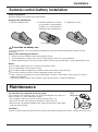
7
Precaution on battery use
Incorrect installation can cause battery leakage and corrosion that will damage the remote control
transmitter.
Observe the following precautions:
1. Always use new batteries when replacing the old set.
2. Do not attempt to charge, short-circuit, disassemble, heat or burn used batteries.
3. Battery replacement is necessary when remote control acts sporadically or stops operating this unit.
Notes:
•
Do not drop, apply shock to or step on the remote control.
•
Do not spill water on the remote control.
•
Do not place objects between the remote control and remote control receiver.
•
Do not use remote controls for other equipment at the same time.
•
If the TV does not operate even when operating the remote control from a close range, it is time to
replace the batteries.
Refer to the label on back of the remote control for directions on replacing batteries.
Requires two AA batteries.
1. Open the battery cover.
2. Install the batteries as shown
in the battery compartment.
(Polarity + or – must match the
markings in the compartment).
3. Replace the cover.
Replacing batteries
Replace batteries by following the steps below:
Two AA size
Installation
Remote control battery installation
CAUTION :
If water or similar substances get inside the monitor via the liquid crystal panel surface, a malfunction may result.
To clean this unit, wipe with a soft, dry cloth.
If the surfaces are extremely dirty, use a soft cloth dipped in a soap and
water solution or a weak detergent solution.
• Use eyeglass cleaner to remove stubborn dirt from the LCD.
• Never use alcohol, paint thinner or benzine to clean this unit.
• Before using a chemically treated cloth, read the instructions that came
with the cloth carefully.
Mild
detergent
Maintenance

8
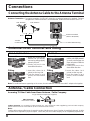
Connections
Connecting the Antenna Cable to the Antenna Terminal
ANT
ANT
UHF Antenna
Antenna Terminal
(ANT or VHF/UHF)
VHF Antenna
Mixer
75 Ohm
Coaxial Cable
Coaxial Antenna Plug
Antenna Connection - For proper reception of VHF/UHF channels, an external antenna is required. For best
reception an outdoor antenna is recommended. Antenna Mode must be set to TV.
Incoming 75 Ohm Cable from Home Antenna / Cable Company
Note:
Certain cable systems offset some channels to reduce interference or have Premium (scrambled) channels. A cable
converter box is required for proper reception. Check with your local Cable company for its compatibility requirements.
Antenna / Cable Connection
Antenna cover removal and fitting
Removal
1
2
1.Grasp the cover at the
bottom end and initially
remove by pulling slightly
toward yourself.
2.Slowly pull out in the
downward direction.
TC-14LA1/TC-17LA1
2
1
Removal
1.
Grasp the opening and initially
pull the cover slightly towards
yourself to disengage the
claws (at 2 points on both the
left and right).
2.Slowly pull out in the
downward direction.
TC-20LA1
ANT (VHF/UHF)
on the Back of the TV
F-Type Antenna Adapter (not supplied)
Note:
To avoid interference appearing on the screen, do not bundle the antenna wire and AC adapter wire together.
Cable Connection - For reception of cable channels (01 - 125) connect the cable supplied by your local cable company.
Antenna Mode must be set to CABLE. (Refer to Antenna Mode section.)
2
1
1.Insert the claws (at 4
points) at the top end.
2.Push the claws in (at 4
points) at the bottom
end.
Fitting
1.Insert the claws (at 4
points) at the top end.
2.Push the claws in (at 4
points) at the bottom
end.
2
1
Fitting

9
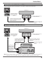
Connections
Use this configuration when connecting the TV to a cable TV system using a Cable Box.
Antenna Connection (Cable Box, no VCR)
Use this configuration when connecting the TV to a cable TV system using a Cable Box and VCR.
Antenna Connection (Cable Box, and VCR)
ANT
ANT
Connect the cable from the Output
terminal on the back of the Cable
Box to the ANTENNA terminal on
the back of the TV.
CABLE BOX
TERMINALS ON THE BACK OF
THE CABLE BOX
Incoming Cable from
Antenna or Cable TV
System
OUTPUT INPUT
ANTENNA TERMINAL
(ANT or VHF/UHF)
ON THE BACK OF
THE TV
ANT
ANT
OUTPUT
S VIDEO
VIDEO
L-AUDIO-R
Connect the
cable from the
Antenna Output
terminal on the
back of the VCR
to the Antenna
terminal (ANT or
VHF/UHF) on the
back of the TV.
Connect the cable from the
Output terminal on the back
of the Cable Box to the
Antenna Input terminal on
the back of the VCR.
ANTENNA TERMINAL
(ANT or VHF/UHF)
ON THE BACK OF
THE TV
VCR
CABLE BOX
TERMINALS ON THE BACK OF
THE CABLE BOX
Incoming Cable from
Antenna or Cable TV
System
OUTPUT INPUT
TO VCR
Connect the cable from the
antenna or cable system to the
Input terminal on the back of the
CABLE BOX.
ANT OUTPUT
ANT INPUT
Note: When the antenna cable is connected to the TV antenna terminal via a cable box or VCR, set the TV
channel to CH3 or CH4, cable. This does not apply when signal is input from VIDEO INPUT.

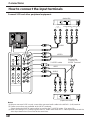
10
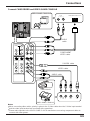
How to connect the input terminals
Connections
Connect VCR and other peripheral equipment
ANT
DC IN 15V
L
R
AUDIO
1
INPUT
VIDEO
S-VIDEO
L
R
AUDIO
2
VIDEO
S-VIDEO
L
R
AUDIO
COMPORNENT VIDEO INPUT
VIDEO
P
B
Y
P
R
L
R
AUDIO
1
INPUT
VIDEO
S-VIDEO
L
R
AUDIO
2
VIDEO
S-VIDEO
L
R
AUDIO
COMPORNENT VIDEO INPUT
VIDEO
P
B
Y
P
R
S-VIDEO cable
VIDEO
AUDIO
(Super-VHS VCR)
(DVD/STB)
Audio
OUTRL
S-Video
OUT
Video
OUT
VIDEO
PrPbY
COMPONENT VIDEO OUT
AUDIO
Audio
OUT
L
R
Connect the
S-VIDEO or
VIDEO Terminal.
Notes:
(1) When a monaural VCR is used, connect the monaural audio cable to the AUDIO-L (Left) terminal.
(2) Similar connections are available at the INPUT terminals.
Select the desired VIDEO input position by pushing the TV/VIDEO button. (See page 14)
(3) When connecting VCRs, priority is given to the S- Video cable when the S- Video input terminal and the
video input terminal are connected at the same time.

11
ANT
DC IN 15V
L
R
AUDIO
1
INPUT
VIDEO
S-VIDEO
L
R
AUDIO
2
VIDEO
S-VIDEO
L
R
AUDIO
COMPORNENT VIDEO INPUT
VIDEO
P
B
Y
P
R
L
R
AUDIO
1
INPUT
VIDEO
S-VIDEO
L
R
AUDIO
2
VIDEO
S-VIDEO
L
R
AUDIO
COMPORNENT VIDEO INPUT
VIDEO
P
B
Y
P
R
Audio
OUTLR
S-Video
OUT
Video
OUT
COMPONENT
VIDEO cable
VIDEO GAME CONSOLE
Audio
OUT
L
R
S-VIDEO cable
VIDEO cable
AUDIO cable
COMPONENT VIDEO OUT
AUDIO
cable
VIDEO GAME CONSOLE
CAMCORDER
Connections
Connect CAMCORDER and VIDEO GAME CONSOLE
Notes:
•
When connecting video cables, priority is given to the S-Video cable when the S-Video input terminal
and the video input terminal are connected at the same time.
•
Please make inquiries to the VIDEO GAME PLAYER manufacture concerning component cables to
connect with video games.

12
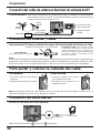
Cable cover removal and fitting
Connections
Note:
Depending on the type of cable used it may not be possible to close the cover. In such cases the cable may be
routed through the antenna cover.
Connect headphones / earphones as follows.
ANT
DC IN 15V
(Optional)
(M3 plug)
Use Volume Up
or Down button to control volume level. (See page 15)
Connecting Headphones / Earphones
Removal
1.Disengage the claws at the
uppermost end.
2.Slowly pull out in the
upward direction.
Fitting
1.Insert the claws (at 2 points)
at the bottom.
2.Push in the TOP.
1
2
1
2

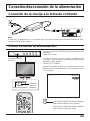
13
Power ON / OFF
Connecting the Plug to the Wall Outlet
ANT
DC IN 15V
2
2
1
3
Note:
•
The TV and AC adaptor will still consume some power as long as the power cord is still inserted into the wall outlet.
•
Be sure to use the power cord and AC adaptor included in the accessories.
•
Usage of AC adapters other than specified may cause malfunctions.
How to Turn the Power On
Press the Main POWER switch on the TV to turn the set on.
POWER-ON: Green
When the set is on or in standby mode press the Main
POWER switch on the TV to turn the set off.
POWER-OFF: No light
Example: The screen below is displayed for a while after
the TV is turned on. (setting condition is an
example.)
POWER
TV/VIDEO VOLUME CHANNEL
Remote control
signal sensor
Power Indicator
Main Power switch
Press the POWER button on the remote
control to turn the TV off: Red (standby)
Press the POWER button on the remote
control to turn the TV on: Green
CH 6
STEREO
SAP
MONO
4 : 3

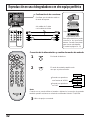
14
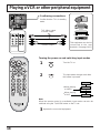
Playing a VCR or other peripheral equipment
ANT
DC IN 15V
L
R
AUDIO
1
INPUT
VIDEO
S-VIDEO
L
R
AUDIO
2
VIDEO
S-VIDEO
L
R
AUDIO
COMPORNENT VIDEO INPUT
VIDEO
P
B
Y
P
R
L
R
AUDIO
1
INPUT
VIDEO
S-VIDEO
L
R
AUDIO
2
VIDEO
S-VIDEO
2
3
The input mode changes each time
this button is pressed.
Operate the connected equipment.
Confirming connections
Confirm that the TV is in standby
mode.
VCR
Laser Disc Player
DVD player
Turning the power on and switching input modes
This equipment can also be
connected to the rear
terminals. (See page 10,11)
Note:
When the remote control is unavailable, input modes can also be
switched using the TV/VIDEO button on the TV set.
TV
VIDEO1
COMPONENT
VIDEO2
Camcorder
Turn the TV on.
1
To S-Video output
or Video output
To Audio output
•
When playing
a VIDEO
•
When playing
a DVD

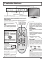
15
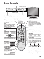
Basic Controls
SLEEP button
The LCD TV may be preset to switch
to stand-by after a fixed period. The
setting changes to 30 minutes, 60
minutes, 90 minutes and 0 minutes
(SLEEP timer cancelled) each time
this button is pressed.
When 3 minutes remain, “
3 ” will
flash. The SLEEP timer is cancelled
if a power interruption occurs.
Before the timer automatically turns
the power off, the remaining time will
blink on the screen (“3” for 3 minutes,
“2” for 2 minutes and “1” for 1 minute
before the power goes off).
Power button
Press to turn this set ON or OFF.
(See page 13)
Note:
The LCD TV’s power cord must
first be plugged into the wall
outlet and then turned on at the
Main POWER switch.
Direct program number
Selection buttons
TV/VIDEO button
The input mode
changes each time
this button is pressed.
MENU
ADJUST
PICTURE
AUDIO
SET UP
PICTURE ADJUST
AUDIO ADJUST
30 60
0
90
R-TUNE button
Switches to previously viewed
channel or video mode.
MUTE button
Press to mute the sound.
Press again to reactivate sound.
Sound is also reactivated when
power is turned off or volume level
is changed.
ASPECT button
MENU button
Press to display
MENU screen,
press again to
clear.
RETURN button
Press to return to the previous
screen.
16 : 9
4 : 3
RECALL button
Press to display time, channel, sleep
timer and other options.
SAP button
Selects Audio mode (See page 21).
Increases volume
Moves cursor to
the right during
menu mode.
Changes to the next channel down
Moves cursor downward during menu
mode.
Changes to the next channel up
Moves cursor upward during menu
mode.
Reduces volume
Moves cursor to
the left during
menu mode.
STEREO SAP MONO
POWER
TV/VIDEO VOLUME CHANNEL
Remote control sensor
Main POWER switch
First press the POWER switch to turn the set on.
<Top Side Controls>
Channel Up/Down
Volume Up/Down
TV/VIDEO button
Operate your Remote control pointed to the Remote control sensor
(Within about 6 meters in front of the TV set.)

16
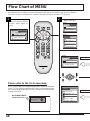
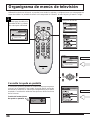
Flow Chart of MENU
All adjustments and setting functions equipped in this set can be made using the menu buttons.
The menu screen is composed of 2 menus, the ADJUST menu and the SET UP menu.
MENU
ADJUST SET UP
LANGUAGE
PROGRAM CH
LOCK
CLOSED CAPTION
INPUT LABEL
OTHER ADJUST
MENU
ADJUST
PICTURE
AUDIO
SET UP
PICTURE ADJUST
AUDIO ADJUST
MENU
ADJUST SET UP
LANGUAGE
PROGRAM CH
LOCK
CLOSED CAPTION
INPUT LABEL
OTHER ADJUST
MENU
ADJUST
PICTURE
AUDIO
SET UP
PICTURE ADJUST
AUDIO ADJUST
MENU selection
or
Press to display MENU
screen, press again to
clear.
1
MENU
ADJUST
PICTURE
AUDIO
SET UP
PICTURE ADJUST
AUDIO ADJUST
An On Screen Help box is displayed whenever a menu is displayed
on the TV. This Help box indicates which keys on the remote control
are used to navigate the menu shown, see above for descriptions
of button functions.
Please refer to the On Screen Help
MANUAL PROGRAM
ENTER CHANNEL
121
RETURN
DELETE
CH SELECT
ADD
ON SCREEN HELP
‘Instruction’ box
2

17
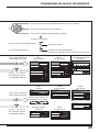
Flow Chart of MENU
CLOSED CAPTION
MODE
OFF
ON MUTE
NO
TO CLOSED
CAPTION
(See page 26)
LANGUAGE
ENGLISH
LANGUAGE
TO LANGUAGE
Allows you to select the
language used for On
Screen Displays.
OFF ON
COOLCOOL
PICTURE ADJUST
NORMAL
PIC MODE
BACK LIGHT
PICTURE
BRIGHTNESS
COLOR
TINT
SHARPNESS
AI PICTURE
+ 30
0
0
0
0
0
OFF ON
STANDARD
TO PICTURE ADJUST
menu
(See page 20)
Press the RETURN
button to return to
previous screen.
Press the RETURN
button to return to
previous screen.
•
To return to previous screen :
•
To end adjustments :
Press to return.
Press to exit from the MENU screen.
This returns the set to the normal viewing condition.
Press to select the desired MENU (ADJUST or SET UP).
Press to select each item.
Press to display each adjustment screen.
Proceed to the adjustment.
Press to display each
adjustment screen.
Press to display each
adjustment screen.
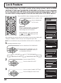
LOCK
BLOCK PROGRAMS
:
STATUS
U. S. MOVIES
CHANGE SETTING
ENTER CODE FIRST
OFF ON
TO LOCK
selection screen
(See page 22 - 25)
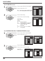
OTHER ADJUST
3D Y/C FILTER
OFF ON
COLOR MATRIX
SD HD
TO OTHER ADJUST
screen
(See page 27)
[ for TC-17LA1 and TC-20LA1 ]
OTHER ADJUST
COLOR MATRIX
SD HD
[ for TC-14LA1 ]
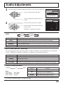
AUDIO ADJUST
NORMAL
MODE
BASS
TREBLE
BALANCE
SURROUND
STEREO SAP MONO
+ 5
+ 2
0
AUTO
OFF ON
TO AUDIO ADJUST
menu
(See page 21)
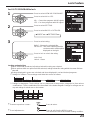
PROGRAM CHANNELS
MODE
AUTO PROGRAM
MANUAL PROGRAM
TV
CABLE
TO PROGRAM
CHANNELS
(See page 18,19)
INPUT LABEL
VIDEO1
VIDEO2
COMPONENT
VIDEO1
VIDEO2
COMPONENT
TO INPUT LABEL
selection screen
(See page 27)

18
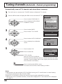
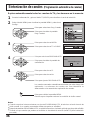
Tuning channels (Automatic channel programming)
Automatically scans all TV channels and stores them in memory.
Notes:
•
When buttons are pressed with AUTO PROGRAM running, the TV set will return to normal viewing.
(Channels searched up to this point are added.)
•
After AUTO PROGRAM is finished, the lowest channel number added will be received.
•
When there are no receivable channels, channel 69 is displayed for TV and channel 125 is displayed
for cable TV.
Press to select PROGRAM CH.
Press to display the PROGRAM
CHANNELS screen.
2
3
Press to select MODE.
Press to select TV or CABLE.
4
Press to select AUTO PROGRAM.
Press to display the confirmation
screen.
5
Press to select YES.
Press to select NO.
If YES selection
press to run AUTO PROGRAM.
Press the MENU button to display the MENU screen and select SET UP.
Channels will automatically advance until all channels have been
scanned. Channel numbers with a video signal present will be stored
in the Channel Scan Memory.
MENU
ADJUST SET UP
LANGUAGE
PROGRAM CH
LOCK
CLOSED CAPTION
INPUT LABEL
OTHER ADJUST
AUTO PROGRAM
Activate
"AUTO PROGRAM?"
YES NO
AUTO PROGRAM
In "AUTO PROGRAM"
STOP
CHANNEL
59
MENU
1
Turn the Power on and press the TV/VIDEO button to display the TV channel.
PROGRAM CHANNELS
MODE
AUTO PROGRAM
MANUAL PROGRAM
TV
CABLE
Press to exit from the MENU screen.
This returns the set to the normal viewing condition.

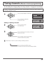
19
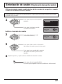
PROGRAM CHANNELS
MODE
AUTO PROGRAM
MANUAL PROGRAM
TV
CABLE
Adding or deleting channels
MANUAL PROGRAM
ENTER CHANNEL
121
RETURN
DELETE
CH SELECT
ADD
MANUAL PROGRAM
ENTER CHANNEL
121
RETURN
DELETE
CH SELECT
ADD
Press to select MANUAL PROGRAM.
Press to display the MANUAL
PROGRAM screen.
1
Press to select channel
(or number keys).
2
3
Press to add channels to memory (Channel
number turns blue).
Press to delete channels from memory
(Channel number turns yellow).
4
Repeat steps 2 and 3 to continue adding or deleting channels.
Press to exit from the MENU screen.
This returns the set to the normal viewing condition.
Tuning channels
(Manual channel programming)
Use this setting when changing setting of receiving channels or changing the channel display.
Turn the TV on and select the broadcast channel. Follow the steps on the previous page to display the
PROGRAM CHANNELS screen.

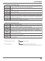
20
Item
BACK LIGHT
PICTURE
BRIGHTNESS
COLOR
TINT
SHARPNESS
AI PICTURE
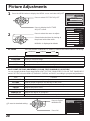
Picture Adjustments
Press the MENU button to display the MENU screen and select ADJUST.
1
2
Press to select PICTURE ADJUST.
Press to display the PICTURE
ADJUST screen.
Press to select the menu to adjust.
Select the desired level by looking at
the picture behind the menu.
NORMAL is displayed at default.
PICTURE MODE is stored for TV, VIDEO1, VIDEO2 and COMPONENT individually.PIC MODE
CINEMA VIVIDSTANDARD
BACK LIGHT, PICTURE, BRIGHTNESS, COLOR, TINT, SHARPNESS, AI PICTURE
You can change the level of each Item (BACK LIGHT, PICTURE, BRIGHTNESS, COLOR, TINT, SHARPNESS
and AI PICTURE) for each MENU (STANDARD, CINEMA, and VIVID ) according to your personal preference.
MENU
ADJUST
PICTURE
AUDIO
SET UP
PICTURE ADJUST
AUDIO ADJUST
OFF ON
COOLCOOL
PICTURE ADJUST
NORMAL
PIC MODE
BACK LIGHT
PICTURE
BRIGHTNESS
COLOR
TINT
SHARPNESS
AI PICTURE
+ 30
0
0
0
0
0
OFF ON
STANDARD
Function
Luminance of the back light is adjusted.
Selects proper brightness and density for the room.
Adjusts for easier viewing of dark pictures such as night scenes.
Adjusts the level of color.
Adjusts for flesh tone color.
Adjusts the degree of sharpness.
Displays black and white colors more clearly when turned ON.
•
To reset to standard setting :
Press to Select
NORMALIZE.
Press OK.
PICTURE ADJUST
NORMALIZE
PIC MODE
BACK LIGHT
PICTURE
BRIGHTNESS
COLOR
TINT
+ 5
0
0
0
0
STANDARD
Function
Displays standard image.
Ideal for watching movies in a dark room.
Displays a clear screen with contrast of light and dark.
MODE
STANDARD
CINEMA
VIVID
Page is loading ...
Page is loading ...
Page is loading ...
Page is loading ...
Page is loading ...
Page is loading ...
Page is loading ...
Page is loading ...
Page is loading ...
Page is loading ...
Page is loading ...
Page is loading ...
Page is loading ...
Page is loading ...
Page is loading ...
Page is loading ...
Page is loading ...
Page is loading ...
Page is loading ...
Page is loading ...
-
 1
1
-
 2
2
-
 3
3
-
 4
4
-
 5
5
-
 6
6
-
 7
7
-
 8
8
-
 9
9
-
 10
10
-
 11
11
-
 12
12
-
 13
13
-
 14
14
-
 15
15
-
 16
16
-
 17
17
-
 18
18
-
 19
19
-
 20
20
-
 21
21
-
 22
22
-
 23
23
-
 24
24
-
 25
25
-
 26
26
-
 27
27
-
 28
28
-
 29
29
-
 30
30
-
 31
31
-
 32
32
-
 33
33
-
 34
34
-
 35
35
-
 36
36
-
 37
37
-
 38
38
-
 39
39
-
 40
40


Panasonic TC17LA1 User manual
- Category
- LCD TVs
- Type
- User manual
Ask a question and I''ll find the answer in the document
Finding information in a document is now easier with AI
in other languages
- español: Panasonic TC17LA1 Manual de usuario
Related papers
-
Panasonic TC22LT1 Operating instructions
-
-
Panasonic TC20LE5 - 20" LCD COLOR TV User guide
-
-
-
-
-
-
-
Other documents
-
Radio Shack PLTVD158 User manual
-
Sharp LC-32LE450U User manual
-
 Eviant T7 series User manual
-
Sanyo DP37647 - 37" Vizzon LCD TV User manual
-
Insignia IS-LCDTV32 User manual
-
Polaroid TLE-04641C User manual
-
HP LC3760N User manual
-
Memorex MLTD2622 Owner's manual
-
-
Hitachi L40A105E User manual
