Dell PowerEdge M605 Quick start guide
- Category
- KVM switches
- Type
- Quick start guide

Dell™ PowerEdge™
M905, M805, M605, and M600
Getting Started
With Your System
系统使用入门
はじめに
시스템시작하기


Dell™ PowerEdge™
M905, M805, M605, and M600
Getting Started
With Your System

Notes, Notices, and Cautions
NOTE: A NOTE indicates important information that helps you make better use
of your computer.
NOTICE: A NOTICE indicates either potential damage to hardware or loss of data
and tells you how to avoid the problem.
CAUTION: A CAUTION indicates a potential for property damage, personal injury,
or death.
____________________
Information in this document is subject to change without notice.
© 2008 Dell Inc. All rights reserved.
Reproduction in any manner whatsoever without the written permission of Dell Inc. is strictly
forbidden.
Trademarks used in this text: Dell, the DELL logo, and Dell OpenManage are trademarks of Dell Inc.;
Microsoft, Windows, and Windows Server are either trademarks or registered trademarks of Microsoft
Corporation in the United States and/or other countries; AMD and AMD Opteron are trademarks of
Advanced Micro Devices, Inc.; Intel and Xeon are registered trademarks of Intel Corporation; SUSE
is a registered trademark of Novell, Inc.; Red Hat and Enterprise Linux are registered trademarks of
Red Hat, Inc.; VMware is a registered trademarks of VMware, Inc. in the United States and/or other
jurisdictions.
Other trademarks and trade names may be used in this document to refer to either the entities claiming
the marks and names or their products. Dell Inc. disclaims any proprietary interest in trademarks and
trade names other than its own.
Model BMX01
May 2008 P/N T550C Rev. A00

Getting Started With Your System 3
System Features
This section describes the major hardware and software features of your
system. It also provides information about other documents you may need
when setting up your system and how to obtain technical assistance.
System Enclosure Features
The M1000e system enclosure (chassis) includes the following features:
Scalability Features
• Support for up to 16 half-height or 8 full-height blades (server modules).
• Support for three layers of I/O fabric, selectable between combinations
of Ethernet, Infiniband, and Fibre Channel modules.
Up to six I/O modules may be installed in the enclosure, chosen from Fibre
Channel switches, Fibre Channel passthroughs, Infiniband switches,
Ethernet switches, and Ethernet passthrough modules.
Reliability Features
• Nine redundant, hot-pluggable system fan modules.
• Three 2360-watt, hot-pluggable power supplies and three power supply
blanks, or six 2360-watt, hot-pluggable power supplies. (Three power
supplies provide power to the system; adding three additional power
supplies provides 3+3 redundancy.)
NOTICE: Power supplies can only connect to a power distribution unit (PDU).
They cannot connect directly to an electrical outlet.
NOTICE: The system enclosure requires a 200-240V power source.

4 Getting Started With Your System
Systems Management Features
• A Chassis Management Controller (CMC), which provides several
essential systems management features:
– Enclosure-level power management and thermal management:
• The CMC monitors system power requirements and supports the
optional Dynamic Power Supply Engagement mode so that the
CMC can enable or place power supplies in standby dynamically,
depending on load and redundancy requirements, to improve
power efficiency.
• The CMC reports real-time power consumption.
• The CMC supports an optional power ceiling, which will either
trigger an alert or actions to keep the enclosure power
consumption under the predefined ceiling.
• The CMC monitors and controls cooling fans based on actual
ambient and internal temperature measurements.
– The CMC provides comprehensive enclosure inventory and
status/error reporting.
– The CMC allows centralized configuration of the following settings:
• The CMC’s network and security settings
• Power redundancy and power ceiling settings
• I/O switches and iDRAC network settings
• First boot device on the blades
– The CMC will check I/O fabric consistency between the I/O modules
and blades and will disable system components if necessary to protect
the system hardware.
– User access security.
– An SD card slot on the CMC card supports an optional persistent
WWN/MAC feature that allows slot-based WWN/MACs for the
blades, simplifying blade installation and replacement.

Getting Started With Your System 5
The CMC has two Ethernet ports. "Gb1" is used to connect to the external
management network. "Stack" allows CMCs in adjacent enclosures to be
daisy-chained. A 24-port Ethernet switch provides internal 100-Mb
communication with the blades, I/O modules, optional iKVM, and
optional second, redundant CMC, and provides a 10/100/1000-Mb
connection to the external management network.
NOTE: The 24-port Ethernet switch is reserved for internal communication
between the iDRAC on the blades to the CMC, then to the external
management network.
A second, optional CMC can be installed for hot-plug failover redundancy.
• An enclosure control panel that includes an LCD display which provides
current infrastructure and blade information, and error reporting.
• An optional Avocent integrated Keyboard, Video and Mouse (iKVM)
module, which includes the following features:
– The iKVM maintains all blade connections as input is switched from
each blade.
– Local iKVM access can be remotely disabled on a per blade basis via
the iDRAC user interface.
– One VGA connector.
– Two USB ports for keyboard and mouse connections.
NOTE: USB functionality is contingent on the connection of a video interface,
such as a monitor cable.
– An RJ-45 ACI port for tiering with external Dell and Avocent analog
KVM and KVM over IP switches with ARI ports. The ACI connection
takes precedence over the rear panel KVM ports.
– The iKVM can also be accessed from the control panel in the front of
the enclosure. Either front or rear KVM functionality is supported
(simultaneous functionality is not supported).
NOTE: The front iKVM is enabled by default if contention exists between the
front and rear iKVM ports. Front iKVM access can be disabled via the CMC
user interface.

6 Getting Started With Your System
Blade Features
Performance Features
PowerEdge M905
• Four AMD
™
Opteron
™
8000 Series dual-core or quad-core processors.
• A minimum of 8 GB of 677 MHz DDR2 memory modules, upgradable to
a maximum of 192 GB by installing pairs of 1-GB, 2-GB, 4-GB, or 8-GB
modules in the 24 memory module sockets on the blade system board.
The blade also supports memory sparing if eight or sixteen memory
module sockets are populated with identical memory modules.
• An SD (Secure Digital) card slot for embedded Hyperviser support.
PowerEdge M805
• Two AMD
Opteron
2000 Series dual-core or quad-core processors.
• A minimum of 4 GB of 677 MHz DDR2 memory modules, upgradable to
a maximum of 128 GB by installing pairs of 1-GB, 2-GB, 4-GB, or 8-GB
modules in the 16 memory module sockets on the blade system board.
The blade also supports memory sparing if eight or sixteen memory
module sockets are populated with identical memory modules.
• An SD card slot for embedded Hyperviser support.
PowerEdge M600
• One or two Intel
®
Xeon
®
dual-core or quad-core processors
• A minimum of 1 GB of 677-MHz FBD memory modules, upgradable to
a maximum of 64 GB by installing pairs of 512-MB, 1-GB, 2-GB, 4-GB,
or 8-GB modules in the eight memory module sockets on the blade system
board. The blade also supports memory sparing or memory mirroring if all
eight memory module sockets are populated with identical memory
modules.

Getting Started With Your System 7
PowerEdge M605
• One or two AMD
Opteron
2000 Series dual-core or quad-core processors.
• A minimum of 1 GB of 677-MHz or 800-MHz DDR2 memory modules,
upgradable to a maximum of 64 GB by installing pairs of 512-MB, 1-GB,
2-GB, 4-GB, or 8-GB modules in the eight memory module sockets on
the blade system board. The blade also supports memory sparing.
Common Features
• The PowerEdge M805 and M905 blades support one or two 2.5 inch SAS
hard drives.
• The PowerEdge M600 and M605 blades support one or two 2.5-inch SATA
hard drives,
or
one or two 2.5 inch SAS hard drives.
NOTE: SAS and SATA hard drives cannot be mixed within a blade.
Hot-plug drive operation is supported if an optional RAID controller card
is installed in the blade.
• Three USB 2.0-compliant ports (PowerEdge M805 and M905) or two USB
2.0-compliant ports (PowerEdge M605 and M600) support devices such as
a mouse, keyboard, flash drive, diskette drive, or an optical drive.
NOTE: Only Dell-supplied USB devices are supported.
• An integrated VGA-compatible video subsystem with an ATI RN50 video
controller. This video subsystem contains 32 MB of SDRAM video
memory (nonupgradable). Maximum resolution is 1280 x 1024 x 65,000
colors (noninterlaced).
• An Integrated Dell Remote Access Controller (iDRAC), which provides
remote system management, blade-level power management, virtual KVM
and virtual media support, remote alerting and event logging.
• Four 1-GB Ethernet ports supported by two integrated dual-port
Broadcom 5709S controllers (PowerEdge M805 and M905), or two 1-GB
Ethernet ports supported by two integrated Broadcom 5708S controllers
(PowerEdge M600 and M605). TCP/IP Offload Engine (TOE) and iSCSI
boot are supported.
For a complete list of system features, see "Technical Specifications" on
page 15.

8 Getting Started With Your System
The following software is included with your system:
• A System Setup program for quickly viewing and changing system
configuration information. For more information on this program, see
"Using the System Setup Program" in your
Hardware Owner’s Manual
.
• Enhanced security features, including a system password and a setup
password, available through the System Setup program.
• System diagnostics for evaluating system components and devices.
For information about the system diagnostics, see "Running the System
Diagnostics" in your
Hardware Owner’s Manual
.
• Video drivers for displaying many popular application programs in high-
resolution modes.
• Systems management software and documentation. Systems management
software is used to manage and monitor each individual blade as well as
the system as a whole, including all of the blades, network switch modules,
power supplies, and fans. Systems management software manages the
system locally and remotely on a network. Dell recommends that you use
the systems management software provided with this system.
• Optional solutions software for Web hosting, caching, or load balancing.
See your solutions software documentation for more information.
Supported Operating Systems
• Microsoft
®
Windows Server
™
2003, Web, Standard and Enterprise
(32-bit x86) Editions with SP2
• Microsoft Windows Server 2003, Standard, Enterprise, and DataCenter
(x64) Editions SP1, SP2
• Microsoft Windows Server 2003 R2 Standard and Enterprise (32- bit x86)
Editions with SP1, SP2
• Microsoft Windows Server 2003 R2 Standard, Enterprise, and DataCenter
(x64) Editions with SP1, SP2
• Microsoft Windows Server 2008, Standard Edition with SP1, SP2,
DataCenter, and EM64T
•Red Hat
®
Enterprise Linux
®
AS, ES, and WS (version 4) and EM64T
• Red Hat Enterprise Linux AS and ES (version 4) (ia32
)

Getting Started With Your System 9
• Red Hat Enterprise Linux Server AS and ES (version 5) (ia32)
• Red Hat Enterprise Linux Server AS, ES, and WS (version 5) and EM64T
•SUSE
®
Linux Enterprise Server 9 (x86_64) with SP3 and EM64T
• SUSE Linux Enterprise Server 10 (x86_64) and EM64T
•VMWare
®
ESX 3.1
• VMWare ESX 3.5
Other Information You May Need
CAUTION: See the safety and regulatory information that shipped with your
system. Warranty information may be included within this document or as a
separate document.
• The
Configuration Guide
provides information on configuring the system
enclosure and the blades.
• The
Rack Installation Guide
or
Rack Installation Instructions
included
with your rack solution describes how to install your system into a rack.
• The
Hardware Owner’s Manual
provides information about system
features and describes how to troubleshoot the system and install or
replace system components. This document may be found on the CDs
that came with your system or at
support.dell.com
.
• The
Dell Chassis Management Controller User’s Guide
provides detailed
information on using the remote management features of the system.
• CDs or DVDs included with your system provide documentation and tools
for configuring and managing your system.
• Systems management software documentation describes the features,
requirements, installation, and basic operation of the software.
• Operating system documentation describes how to install (if necessary),
configure, and use the operating system software.
• Documentation for any components you purchased separately provides
information to configure and install these options.

10 Getting Started With Your System
• Updates are sometimes included with the system to describe changes
to the system, software, and/or documentation.
NOTE: Always check for updates on support.dell.com and read the updates
first because they often supersede information in other documents.
• Release notes or readme files may be included to provide last-minute
updates to the system or documentation or advanced technical reference
material intended for experienced users or technicians.
Obtaining Technical Assistance
If you do not understand a procedure in this guide or if the system does not
perform as expected, see your Hardware Owner’s Manual.
Dell Enterprise Training and Certification is available; see dell.com/training
for more information. This service may not be offered in all locations.
Installation and Configuration
CAUTION: Before performing the following procedure, read and follow the safety
instructions and important regulatory information that shipped with your system.
For additional safety best practices information, see
www.dell.com/regulatory_compliance.
This section describes the steps required to set up your system for the first
time.
Unpack the System
Unpack your system and identify each item. Keep all shipping materials in
case you need them later.

Getting Started With Your System 11
Install the System in a Rack
Install the system in the rack once you have read the "Safety Instructions"
located in the rack installation documentation for your system.
See your rack installation documentation for instructions on installing your
system in a rack. For power and cooling guidelines, see the rack capacity
planner tool on www.dell.com.
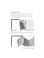
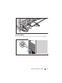
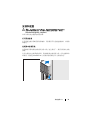
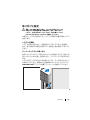
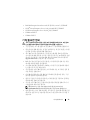
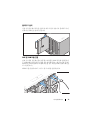
Install the Blades
Beginning at the top, slide the modules into the enclosure from left to right.
When the blade is securely installed, the handle returns to the closed
position.

12 Getting Started With Your System
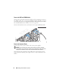
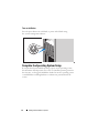
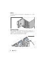
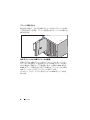
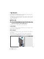
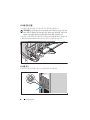
Connect the CMC and KVM Modules
Connect the serial cable and network cable from the management system to
the CMC module. If a second, optional CMC module is installed, connect it
as well. (If your chassis was shipped with M805 or M905 blades pre-installed,
the included CMC firmware will be version 1.2 or greater.)
Connect the keyboard, mouse, and monitor to the optional iKVM module.
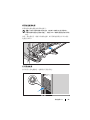
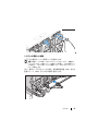
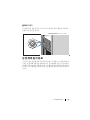
Connect the System to Power
Connect the system’s power cables to the system power supplies.
NOTICE: To prevent the power cables from being disconnected accidentally,
use the plastic clip on each power supply to secure the power cable to the power
supply, and use the Velcro strap to secure the cable to the strain-relief bar.
Next, plug the other end of the power cables into a separate power source
such as an uninterruptible power supply (UPS) or a power distribution unit
(PDU).

Getting Started With Your System 13
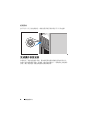
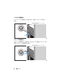
Turn on the System
Press the power button on the enclosure. The power indicator should light.

14 Getting Started With Your System
Turn on the Blades
Press the power button on each blade, or power on the blades using
the systems management software.
Complete the 0perating System Setup
If you purchased a preinstalled operating system, see the operating system
documentation that ships with your system. To install an operating system for
the first time, see the Quick Installation Guide. Be sure the operating system
is installed before installing hardware or software not purchased with the
system.

Getting Started With Your System 15
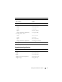
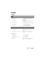
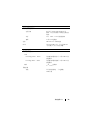
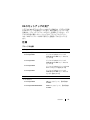
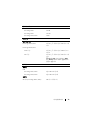
Technical Specifications
Blade Specifications
Processor
Processor type
PowerEdge M905
Four dual-core or quad-core AMD
Opteron 8000 Series processors
PowerEdge M805
Two dual-core or quad-core AMD
Opteron 2000 Series processors
PowerEdge M600
One or two dual-core or quad-core Intel
Xeon processors
PowerEdge M605
One or two dual-core or quad-core AMD
Opteron 2000 Series processors
Memory
Architecture
PowerEdge M600
FBD memory modules, rated for
677-MHz operation
PowerEdge M905, M805, M605
DDR2 memory modules, rated for
677-MHz operation
Memory module sockets
PowerEdge M905
24 240-pin sockets
PowerEdge M805
16 240-pin sockets
PowerEdge M605, M600
Eight 240-pin sockets
Memory module capacities 512 MB (PowerEdge M605 and M600),
1 GB, 2 GB, 4 GB, or 8 GB
Minimum RAM Two memory modules per processor
PowerEdge M905
8 GB (Eight 1-GB memory modules)
PowerEdge M805
4 GB (Four 1-GB memory modules)
PowerEdge M600, M605
1 GB (two 512-MB memory modules)

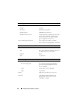
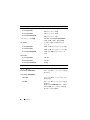
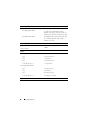
16 Getting Started With Your System
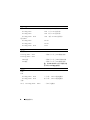
Maximum RAM
PowerEdge M905
192 GB
PowerEdge M805
128 GB
PowerEdge M600, M605
64 GB
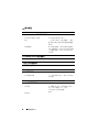
Drives
Hard Drives
PowerEdge M805, M905 One or two 2.5-inch SAS hard drives
PowerEdge M600, M605
SATA configuration
One or two 2.5-inch SATA hard drives
SAS configuration
One or two 2.5-inch SAS hard drives
NOTE: SAS and SATA hard drives cannot
be mixed within a M600 or M605 blade.
Connectors
External
USB
PowerEdge M805, M905
Three 4-pin, USB 2.0 compliant
PowerEdge M600, M605
Two 4-pin, USB 2.0 compliant
Internal
SD Card (PowerEdge M805, M905) One SD card connector
Ethernet Controllers
Chipset
PowerEdge M805, M905
Four Ethernet ports with TOE and iSCSI
boot support, provided by two integrated
dual-port Broadcom 5709S Ethernet
controllers
PowerEdge M600, M605
Two Ethernet ports with TOE and iSCSI
boot support, provided by two integrated
Broadcom 5708S controllers
Memory (continued)

Getting Started With Your System 17
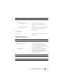
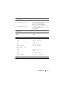
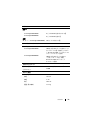
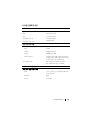
System Enclosure Specifications
Video Controller
Video type ATI RN50 video controller
Video memory 32 MB
Physical
PowerEdge M905, M805
Height
38.5cm (15.2 in)
Width
5 cm (2 in)
Depth
48.6 cm (19.2 in)
Weight (maximum configuration)
11.1 kg (24.5 lb)
PowerEdge M605, M600
Height
18.9 cm (7.4 in)
Width
5 cm (2 in)
Depth
48.6 cm (19.2 in)
Weight (maximum configuration)
5.2-6.4 kg (11.5-14.0 lb)
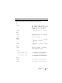
Battery
Blade battery CR 2032 3.0-V lithium ion coin cell
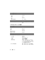
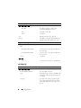
Physical
Height 44.0 cm (17.3 in)
Width 44.7 cm (17.6 in)
Depth 75.5 cm (29.7 in)
Weight (maximum configuration) 178.3 kg (392.2 lb)
Weight (empty) 44.6 kg (98.1 lb)

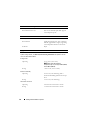
18 Getting Started With Your System
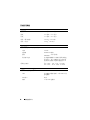
Power Supply Module
AC/DC power supply (per power supply)
Wa tt ag e
2360 W
Connector
NEMA C20 receptacle
Heat dissipation
1205 BTU/hr. maximum
Maximum inrush current
Under typical line conditions and over the
entire system ambient operating range,
the inrush current may reach 55 A per
power supply for 10 ms or less.
System Voltage Requirements
200 - 240V, 16A, 3-Phase, 50 /60Hz
200 - 240V, 40.5A, Single Phase, 50 /60Hz
Optional Avocent iKVM Module
Rear externally accessible connectors
USB
Two 4-pin, USB 2.0-compliant connectors
for keyboard and mouse support
ACI port
RJ-45
Video
15-pin VGA
Chassis Management Controller Module
Externally accessible connectors
Remote management
Two dedicated 10/100/1000 Mb RJ-45
ports for integrated Ethernet remote
access controller.
Serial
9-pin, DTE, 16550-compatible
Video
15-pin VGA
Battery CR 2032 3.0-V lithium ion coin cell
SD Card One dedicated internal SD (Secure
Digital) flash card memory slot for
FlexAddress support.
Page is loading ...
Page is loading ...
Page is loading ...
Page is loading ...
Page is loading ...
Page is loading ...
Page is loading ...
Page is loading ...
Page is loading ...
Page is loading ...
Page is loading ...
Page is loading ...
Page is loading ...
Page is loading ...
Page is loading ...
Page is loading ...
Page is loading ...
Page is loading ...
Page is loading ...
Page is loading ...
Page is loading ...
Page is loading ...
Page is loading ...
Page is loading ...
Page is loading ...
Page is loading ...
Page is loading ...
Page is loading ...
Page is loading ...
Page is loading ...
Page is loading ...
Page is loading ...
Page is loading ...
Page is loading ...
Page is loading ...
Page is loading ...
Page is loading ...
Page is loading ...
Page is loading ...
Page is loading ...
Page is loading ...
Page is loading ...
Page is loading ...
Page is loading ...
Page is loading ...
Page is loading ...
Page is loading ...
Page is loading ...
Page is loading ...
Page is loading ...
Page is loading ...
Page is loading ...
Page is loading ...
Page is loading ...
Page is loading ...
Page is loading ...
Page is loading ...
Page is loading ...
Page is loading ...
Page is loading ...
Page is loading ...
Page is loading ...
Page is loading ...
Page is loading ...
Page is loading ...
Page is loading ...
-
 1
1
-
 2
2
-
 3
3
-
 4
4
-
 5
5
-
 6
6
-
 7
7
-
 8
8
-
 9
9
-
 10
10
-
 11
11
-
 12
12
-
 13
13
-
 14
14
-
 15
15
-
 16
16
-
 17
17
-
 18
18
-
 19
19
-
 20
20
-
 21
21
-
 22
22
-
 23
23
-
 24
24
-
 25
25
-
 26
26
-
 27
27
-
 28
28
-
 29
29
-
 30
30
-
 31
31
-
 32
32
-
 33
33
-
 34
34
-
 35
35
-
 36
36
-
 37
37
-
 38
38
-
 39
39
-
 40
40
-
 41
41
-
 42
42
-
 43
43
-
 44
44
-
 45
45
-
 46
46
-
 47
47
-
 48
48
-
 49
49
-
 50
50
-
 51
51
-
 52
52
-
 53
53
-
 54
54
-
 55
55
-
 56
56
-
 57
57
-
 58
58
-
 59
59
-
 60
60
-
 61
61
-
 62
62
-
 63
63
-
 64
64
-
 65
65
-
 66
66
-
 67
67
-
 68
68
-
 69
69
-
 70
70
-
 71
71
-
 72
72
-
 73
73
-
 74
74
-
 75
75
-
 76
76
-
 77
77
-
 78
78
-
 79
79
-
 80
80
-
 81
81
-
 82
82
-
 83
83
-
 84
84
-
 85
85
-
 86
86


Dell PowerEdge M605 Quick start guide
- Category
- KVM switches
- Type
- Quick start guide
Ask a question and I''ll find the answer in the document
Finding information in a document is now easier with AI
in other languages
Related papers
Other documents
-
Samsung M600 User manual
-
Eten M600 User manual
-
Polar Electro M600 User manual
-
-
Fujitsu Siemens Computers KVM s3-1621 User manual
-
Fujitsu s3-1621 User manual
-
-
-
NEC N8406-017 User guide
-
Brocade Communications Systems 53-1002580-01 User manual