Thermador DWHD770WPR Installation guide
- Category
- Dishwashers
- Type
- Installation guide

Installation
INSTRUCTIONS
Dishwasher
THERMADOR.COM


3
Table of
CONTENTS
Safety Definitions .................................3
Safety Instructions .................................4
Avoiding General Hazards ...........................4
Tools & Materials ..................................5
Enclosure Requirements ............................7
Electrial Connections ...............................9
Installation of Mounting Brackets ....................12
Positioning the Dishwasher .........................13
Securing the Dishwasher ...........................15
Water Inlet Connection ............................16
Drain Connection ................................17
Attaching the Toe Panel ...........................18
Fully Integrated Door Panel ........................19
Customer Service ................................20
This THERMADOR Appliance is made by
BSH Home Appliances Corporaton
1901 Main Street, Suite 600
Irvine, CA 92614
Questions?
1-800-735-4328
ww.thermador.com
We look forward to hearing from you!
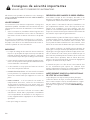
Safety Definitions
NOTICE : This indicates that damage to the appliance or
property may occur as a result of non-compliance with this
advisory.
This indicates that death or serious injuries may occur
as a result of non-observance of this warning.
WARNING
Note: This alerts you to important information and/or tips.
This indicates that minor or moderate injuries may
occur as a result of non-observance of this warning.
CAUTION
!
!

4
To avoid possible injury or property damage, OBSERVE ALL
WARNINGS AND CAUTIONS.
WARNING:
These instructions are intended for use by qualified installers
only. The dishwasher must be installed by a qualified service
technician or installer.
• In addition to these instructions, the dishwasher shall be
installed to meet all electrical and plumbing codes and
ordinances (both national and local).
Read these installation instructions completely and follow them
carefully. They will save you time and effort and help to ensure
safety and optimum dishwasher performance.
IMPORTANT
• The dishwasher drain hose must be installed with a por-
tion of it at least 33 in (84 cm) off the floor; otherwise the
dishwasher may not drain properly.
• This dishwasher is intended for indoor residential use
only, and should not be used in commercial food service
establishments.
• This dishwasher is designed to be enclosed on the top and
both sides by cabinetry.
• NEW INSTALLATION - If the dishwasher is a new
installation, ensure all connections are properly made
before the dishwasher is moved into place.
• REPLACEMENT - If the dishwasher is replacing another
dishwasher, check the existing dishwasher connections for
compatibility with the new dishwasher, and replace parts
as necessary.
• This appliance has been found to be in compliance with
CAN/CSA-C22.2 No. 167/UL 749. It is the responsibility
of the owner and the installer to determine if additional
requirements and standards apply in specific installations.
• Not for outdoor use.
IMPORTANT SAFETY INSTRUCTIONS
PLEASE READ AND SAVE THIS INFORMATION
AVOIDING GENERAL HAZARDS
To reduce the risk of electric shock, fire, or injury to persons,
the installer must ensure that the dishwasher is completely
enclosed at the time of installation.
Do not use the dishwasher until it is completely installed.
When opening the door on an uninstalled dishwasher, carefully
open the door while supporting the rear of the unit. Failure to
follow this warning can cause the dishwasher to tip over and
result in serious injury.
Before installing the supplied counter top mounting brackets,
decide which method will be used to secure the dishwasher
into its opening. Once these mounting brackets are installed
on the dishwasher, removing them is difficult and will damage
the mounting brackets and the dishwasher.
In some conditions, hydrogen gas can form in a hot water
system that has not been used for weeks. Hydrogen gas is
explosive. Before filling a dishwasher from a system that has
been off for weeks, run the water from a nearby faucet in a
well ventilated area until there is no sound or evidence of gas.
Removing any cover or pulling the dishwasher from the cabinet
can expose hot water connections, electrical power and sharp
edges or points. Handle with care.
STATE OF CALIFORNIA PROPOSITION 65
WARNING:
This product can expose you to chemicals including vinyl
chloride, which is known to the State of California to cause
cancer and birth defects or other reproductive harm. For more
information go to www.P65Warnings.ca.gov.
!

5
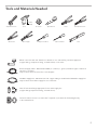
Elbow connection with 3/4” female hose threads on one end and fits your water supply line
(copper tubing, compression fitting, or braided hose) on the other.
Electrical Supply Cable - Minimum #14 AWG, 2 conductor, 1 ground, insulated copper conductors
rated 75° C or higher.
Only needed if house electrical line is not adequate.
Hot Water Supply Line - Minimum 3/8” O.D. copper tubing or metal braided dishwasher supply line.
Only needed if house water supply line is not sufficient.
Shut-off valve and fittings appropriate for hot water supply line
(copper tubing/compression fitting, or braided hose).
UL listed conduit connector or strain relief is required if you attach the field wiring directly
to the terminal block.
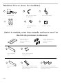
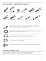
Tools and Materials Needed
Wire Cutter
Needle Nose Pliers
Pliers
Wire Stripper
ø1/16 in
(2 mm)
Adjustable wrench
Tape Measure
Drill
Hole Saw
Flat Screwdriver
Level
Phillips Screwdriver

6
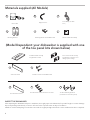
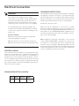
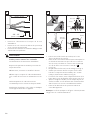
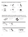
Materials supplied (All Models)
Screw Clamp (for drain
hose)
Junction Box
Edge Protector
Mounting Brackets
Mounting Bracket Screws Ø 4x13 mm
Adhesive Backed Cord Clip
D
E
F
B
A C
(Model Dependent: your dishwasher is supplied with one
of the toe panel kits shown below)
Slotted Toe Panel
Installation Guide for Fully
Integrated Door Panel
Slotted Toe Panel Screws Ø 4x16 mm
Non-Slotted Toe Panel
Non-Slotted Toe Panel Stainless steel screws
Toe Panel Mounting Brackets
(used with non-slotted toe panel)
G
H
I
J
K
Door release handles for fully
integrated door panels for use
during a power outage.
INSPECT THE DISHWASHER
After unpacking the dishwasher and prior to installation, thoroughly inspect the dishwasher for possible freight or cosmetic damage.
Report any damage immediately. Cosmetic defects must be reported within 30 days of installation.
NOTE: Do not discard any bags or items that come with the original package until after the entire installation has been completed.

7
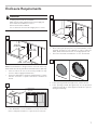
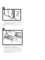
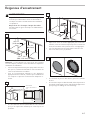
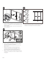
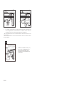
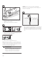
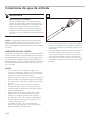
Enclosure Requirements
Scalding or Electrical Shock Hazard!
Make sure the water supply and electrical supply are
shut off before installation or service.
Electrical Shock/Fire Hazard!
Do not allow the electrical and supply lines to touch.
Note: This dishwasher is designed to be enclosed on the top,
back and both sides by standard residential kitchen cabinetry.
• Select a location as close to the sink as possible for easy
access to water supply and drain lines.
• For proper dishwasher operation and appearance, ensure
that the enclosure is square and has the dimensions
shown.
• If the dishwasher is to be installed in a corner, ensure that
there is adequate clearance to open the door as shown.
min 34"
(864 mm)
min 24"
(610 mm)
23
5/8
" - 24
1/4
"
(600 - 616 mm)
1
2
WARNING
• After locating the proper place for your dishwasher, create
required openings in your cabinets in order to allow for
water, drain and electrical lines on the appropriate side.
• The holes should be cut within the 7 x 2.5" area shown.
7"
(177.8 mm)
3
•
If the opening is made through wood, sand it smooth.
• If the opening is made through metal, use the provided
edge protector (B) or other approved method to protect
wiring from damage.
4
!

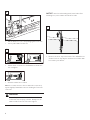
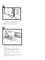
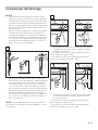
8
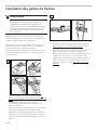
• Pull the drain hose out of the packaging base as shown.
• Set toe panel aside for later use.
b
a
5
•
Attach elbow connection to dishwasher as shown. Do
not overtighten.
NOTICE : Avoid cross-threading! It will cause leaks. After
attaching hose, turn on water and check for leaks.
• Attach hot water line to elbow.
Note: For a easier access to the hot water inlet connection,
tip unit slightly forward with someone holding the front side
of the unit.
6
• Remove the hose clip at the back of the dishwasher as
shown. The hose clip may be used later to hold the drain
hose inside your cabinet.
7
b
a
DO NOT tip the dishwasher too far forward! This
could cause serious injury or death. Always have an
adult hold the front side if the unit is tipped.
WARNING
!

9
Electrical Connection
Avoid Electrical Shock Hazard!
Do not work on an energized circuit. Doing so
could result in serious injury or death. Only qualified
electricians should perform electrical work. Do not
attempt any work on the dishwasher electric supply
circuit until you are certain the circuit is de-energized.
To avoid possible injury or property damage, care
should be exercised when the dishwasher is installed
or removed to reduce the likelihood of damage to the
power cord.
Avoid Fire Hazard!
Make sure electrical work is properly installed and
checked by qualified electricians.
Make sure there are no loose electrical connections.
Make sure all electrical connections are properly made.
WARNING
GROUNDING INSTRUCTIONS
The dishwasher must be properly grounded before operating.
This appliance must be connected to a grounded metal per-
manent wiring system or an equipment grounding conductor
must be run with the circuit conductors and connected to the
equipment grounding terminal or lead on the dishwasher.
Do NOT use extensions cords.
Make sure that the dishwasher is connected to a suitable
ground in compliance with all local codes or, in the absence of
a local code, with the NATIONAL ELECTRICAL CODE in the
United States or the CANADIAN ELECTRIC CODE C22.1-lat-
est edition in Canada as well as any provincial/state or munici-
pal or local codes that apply.
Note: Installations employing a Receptacle - The accessory
cord kit, Model SMZPC002UC, designed for connection to
a receptacle is not provided, but can be ordered through
Customer Service by calling 1-800-944-2904. Make sure the
household receptacle meets the electrical supply requirements
as well as national and local codes. If you choose to permanently
connect to hardwiring, follow the next steps.
DISHWASHER ELECTRICAL RATING
Volts Hertz Amperes Watts
120 60 12 1,440
(max)
ELECTRICAL SUPPLY
The customer has the responsibility of ensuring that the dish-
washer electrical installation is in compliance with all national
and local electrical codes and ordinances. The dishwasher is
designed for an electrical supply of 120V, 60 Hz, AC, connect-
ed to a dishwasher-dedicated, properly grounded electrical
circuit with a fuse or breaker rated for 15 amps. Electrical sup-
ply conductors shall be a minimum #14 AWG copper wire rat-
ed at 75°C (167°F) or higher.
!

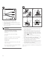
10
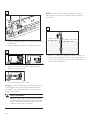
• Turn off any electricity to installation area.
• Remove screws and cover from junction box (A) and
set aside for later use.
• Remove outer casing and insulation of the hardwiring/
power cord as shown.
8
Loose and improperly installed electrical
connections can result in overheating!
Carefully review terminal block installation
instructions.
To avoid risk of fire, observe the following
precautions:
DO NOT remove, bypass or alter the terminal block.
DO NOT cut or splice the power cord or the
accessory cord
using wire nuts.
Only use the recommended accessory cord for wall
socket connections.
Do not use an extension cord, or any type modified
cord or adapter with this appliance.
WARNING
• Attach an approved strain relief (not provided) to oppo-
site side of junction box.
• Without adjusting the terminal screws, insert the wires
properly in the terminal. Make sure that the black wire
connects with the black (L) and the white connects with
the white (N) and the green or bare copper wire with the
green (G or ). (See box b)
• Do NOT insert wire underneath the screw clamp. (see
box a)
• Be certain the wire insulation is not trapped in the termi-
nal. 1-2 mm of wire must be visible (See box b)
• After inserting wire, completely tighten the terminal
screws by turning clockwise. (See box c)
• After tightening the terminal screws, pull on each wire to
ensure that they are secure. Wire should not be loose in
the terminal after correct installation.
• Secure the wire in the junction box with the strain relief.
Note: The arrow (shown in box d above) should align with the
power cord.
9
a
b
cd
1-2 mm
ADVERTENCIA
WARNING
AVERTISSEMENT
STRICTLY FOLLOW ALL INSTRUCTIONS IN THIS MANUAL.
USE ONLY 14 OR 12 AWG COPPER WIRE WITH A MIN. TEMP. RATING
OF 75°C (167°F).
PLACE ALL WIRING IN THE POWER SUPPLY BOX AND INSTALL COVER.
CONNECTION SCREWS ARE NOT REMOVABLE.
ESTRICTAMENTE SIGA TODAS LAS INSTRUCCIONES DE ESTE MANUAL.
UTILICE SÓLO EL 14 O 12 DE ALAMBRE DE COBRE AWG CON UN GRADO
DE LA TEMPERATURA MÍNIMA DE 75 ° C (167 ° F).
COLOQUE TODOS LOS CABLES EN LA CAJA DE LA FUENTE DE ALIMEN-
TACIÓN Y LA INSTALACIÓN DE LA CUBIERTA. TORNILLOS DE CONEXIÓN
NO SON EXTRAIBLES.
WIRE STRIP GAGE
1/2" (13 mm)
CALIBRE DE POUR DÉNUDER
INDICADOR DE CABLE PELADO
OBSERVER TOUTES LES INSTRUCTIONS DE CE GUIDE.
UTILISER SEULEMENT DU FIL DE CUIVRE 14 OU 12 AWG AVEC UNE
COTE DE TEMPÉRATURE MINIMALE DE 75°C (167°F).
PLACER TOUS LES FILS DANS LA BOÌTE D‘ALIMENTATION ET
REMETTRE LE COUVERCLE.
LES VIS DE CONNEXIONS NE SONT PAS AMOVIBLES.
view with cover installed
arrow
strain relief
black (L)
white (N)
green (G)
A
!

11
• Check all electrical connections to ensure they are secure
and then reattach the junction box cover.
• Place adhesive backed cord clip (provided in the
installation kit) 5 inches from leg adjuster as shown in
the figure above and route power cord through the clip.
Note:The length of cord measured from the plastic back
strap to the receptacle should be ≤ 47.25” (1,200 mm).
• Plug the end of the supply cord into the back of the
dishwasher as shown until it clicks.
CLICK
Adhesive
backed
cord clip
Leg Adjuster
Strap
5"
(127 mm
)
C
l
ip
o
rie
ntation
A
lternate cable routing
11
10
•
Mount the dishwasher electrical supply junction box (A)
and dedicated receptacle in an accessible cabinet adjacent
to the dishwasher (do not mount the junction box or
receptacle behind the dishwasher).
Note: Screws are not provided for mounting electrical supply
junction box.
A

12
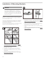
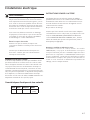
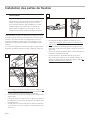
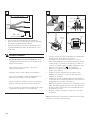
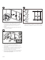
Installation of Mounting Brackets
• Top Mount is used for counter tops made of wood or
other materials that can be easily drilled. If you have
solid surface, marble, granite, or other very hard counter-
tops, skip to step 13 now.
• If insulation is covering the area in 12a, fold it back.
• Orient the mounting brackets (D) for top mounting as
shown in12b.
• Using pliers, bend side flanges down as shown in 12c
and 12d so the bracket will not slip out of slot in frame.
Do not attach to cabinet yet.
Avoid Tip Over Hazard!
Do not use the dishwasher until it is completely
installed. When opening the door on an uninstalled
dishwasher, carefully open the door while supporting
the rear of the unit. Failure to follow this warning can
result in serious injury.
WARNING
Note: Before installing the supplied counter top mounting
brackets, decide which method of securing the dishwasher
into its enclosure will be used.
Once the mounting brackets are installed on the dishwasher,
removing them is difficult and will damage the mounting
brackets and the dishwasher.
If you have a Fully Integrated Panel, do not attach mounting
brackets until after attaching the panel to the door.
12
• Side Mount is used for counter tops made of marble,
granite, or other very hard materials that cannot be easily
drilled.
• Grasp mounting bracket (D) with pliers and fold bracket at
the perforation over onto itself as shown in 13a.
• Slip bracket flange through side slots in frame as shown
in 13b.
• Using pliers, bend side flanges down as shown in 12c and
12d so the bracket will not slip out of slot in frame. Do not
attach to cabinet yet.
13
!

13
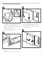
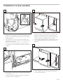
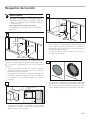
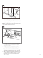
• If your sink is to the right side of where you are installing
the dishwasher, you will need to reposition the hoses and
power cord behind the dishwasher before installing.
• To do so, unhook the strap that the hoses are running
through on the back of the dishwasher base and position
them per your requirements.
• If your sink is to the left side, leave the hoses and power
cord as they came and skip to step 16.
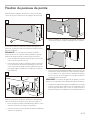
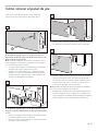
Positioning the Dishwasher
• Reposition the hoses so they run through the strap on the
other side.
• Be sure to snap the strap back in place to secure the hoses
as shown.
15
• To avoid scratching the floor, use floor protection and
caution when sliding the dishwasher into the cabinet. Use
hands on both sides of dishwasher to push evenly.
• Pull water inlet, drain hose and power cord through the
hole in cabinet as shown.
16
14
• Push the unit 2/3 of the way into the opening and stop.
17

14
• Reach into adjacent cabinet and pull hoses and excess
power cord completely out so they do not get kinked.
• Push the unit in until flush with cabinet door.
18
•
After pushing the unit in, adjust the legs as shown to raise
the unit so it is flush with the counter.
• Level side to side by turning feet clockwise to raise or
counter-clockwise to lower front of the unit as shown.
• Place a level on the door to see if the unit is level front
to back. To make adjustments, turn the center screw
clockwise to raise or counter-clockwise to lower the back.
• Place a level on the the counter-top to be sure the unit
isn’t pushing up against the counter.
19
•
Center the dishwasher in the opening before securing it to
your cabinet or counter top as shown.
20

15
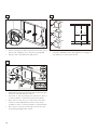
Securing the Dishwasher
• Drive the mounting screws (E) through the holes in the
mounting brackets as shown for Top ( figure 21) or Side
Mount (figure 22).
21
22
E
E

16
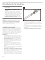
Water Inlet Connection
HOT WATER SUPPLY
The hot water heater should be set to deliver approximately
120° F (49° C) water to the dishwasher. Water that is too hot
can cause some detergents to lose effectiveness. Lower water
temperatures will increase run times. The hot water supply
pressure must be between 15 - 145 psi (1 - 10 bar).
IMPORTANT NOTES:
• If using a solder joint instead of a compression fitting, be
sure to complete all solder connections before connecting
the water supply line to the dishwasher.
• Make sure there are no sharp bends or kinks in the water
line that might restrict water flow.
• Always use appropriate seals when making plumbing
connections.
• Before connecting the water supply line to the dishwasher,
flush the incoming water line for approximately 5 minutes
to clear any foreign material.
• Properly tighten all water connections. Not doing so could
result in a leak.
• Check local plumbing codes for approved plumbing pro-
cedures and accessories. All plumbing should be done in
accordance with national and local codes.
• If using copper tubing or other material not depicted in
this manual for water supply, defer to a licensed plumber
for proper installation.
SCALDING HAZARD!
Do not perform any work on a pressured hot water line.
Serious injury could result. Only qualified plumbers
should perform plumbing work. Do not attempt any
work on the dishwasher hot water supply plumbing
until you are certain the hot water supply is shut off.
WARNING
NOTICE : Temperatures required for soldering and
sweating will damage the dishwasher. If plumbing lines are
to be soldered or sweated, keep the heat source at least 6
inches (152.4 mm) away from the dishwasher.
• Connect the dishwasher water supply line to the water
shut off valve. If one isn’t already in the supply line, install
one (not provided).
• You will need to use an approved dishwasher water
supply line with the correct fittings for this connection.
• After all connections are made, turn on the hot water and
check for leaks.
23
!

17
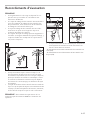
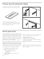
Drain Connection
IMPORTANT NOTES about your drain connection:
• If local ordinance require an air gap, install it according to
the manufacturer’s instructions.
• If the dishwasher drain hose is to be connected to a dis-
poser dishwasher drain connection, remove the plug from
the disposer’s dishwasher drain connection.
• The dishwasher drain hose must have one place along its
length that is securely attached 33" (508 mm) above the floor.
• The drain hose length can be extended if necessary. The
maximum length of the drain hose, including the hose
leading to the air gap, is 150" (380 cm).
• You may use the piece you removed in Step 7 to attach to
the inside of the adjacent cabinet and hang the drain hose
from as shown (screws are not supplied) in place of using
a Nonmetallic Tie as pictured in the next illustrations. Do
not exceed 43” in drain hose height.
• The dishwasher drain hose must be installed with a portion
of it at least 33” (84 cm) off the floor; otherwise the dish-
washer may not drain properly.
Note: Place hose clamp (C) around end of drain hose BEFORE
connecting to the plumbing.
24
min 33” (84 cm)
max 43” (110 cm)
min 33” (84 cm)
max 43” (110 cm)
• The dishwasher drain hose may be connected to the drain
plumbing using an air gap in one of two ways:
- Connect to the under sink dishwasher drain connection (25a).
- Connect to a disposer dishwasher drain connection (25b).
• The dishwasher drain hose may be connected to the drain
plumbing using a high loop in one of two ways:
- Connect to the under sink dishwasher drain connection (25c).
- Connect to a disposer dishwasher drain connection (25d).
25
a
C
C
C
• Use the clamp provided (C) to
attach the drain hose to the
house plumbing as shown.
26
C
C
b
c d

18
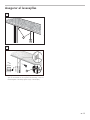
If your dishwasher came with a non-slotted toe panel (I) and
toe panel brackets (K) follow these instructions; otherwise
skip to 31 now.
• Plug metal brackets (K) into openings on both sides of the
base as shown.
• Use screw (J) to mount metal brackets to the base as shown.
28
J K
Attaching the Toe Panel
If your dishwasher came with a slotted toe panel (G) only,
follow these instructions; otherwise skip to 28 now.
Note: If using the slotted toe panel shown in 27 above, then
metal mounting brackets shown in 28 are not required.
• Position the slotted toe panel (G) on the dishwasher. Allow
it to rest on the floor.
• Attach using screws (H) as shown. Use only the supplied
screws to avoid damaging the dishwasher. The toe panel
should be flush with the floor. Your installation is complete!
27
G
H
Before attaching the toe panel, remove the protective film
from the outer door and the toe panel.
• Tuck the pre-attached rubber apron behind the fingers on
the metal brackets as shown.
29
•
Slide metal toe panel into position with folded hem edge at
the top. Make sure the bottom of the toe panel is flush with
the floor. Use screw (J) to mount the toe panel through the
hole it matches up with on the metal brackets (K) as shown.
Note: The toe panel height can be adjusted by screwing into
a different hole in the bracket.
• Check for correct fit of apron by opening the door. Ensure
the apron does not bind up and can freely move up and
down behind the toe panel. Your installation is complete!
30
J
top

19
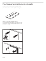
Fully Integrated Door Panel
Please see the included instructions and template for
installing a fully integrated door panel.
Also included - two red door handles.
If your door panel does not have a handle, use these
handles to open the door in the event of a power outage
that would cause the ‘push to open’ feature not to function.

20
Your dishwasher requires no special care other than that
described in the Care and Maintenance section of the Use and
Care Manual. If you are having a problem with your dishwasher,
before calling for service please refer to the Troubleshooting
section in the Use and Care Manual. If service is necessary,
contact your dealer or installer or an authorized service center.
Do not attempt to repair the appliance yourself. Any work
performed by unauthorized personnel may void the warranty.
If you are having a problem with your dishwasher and are not
pleased with the service you have received, please take the
following steps (in the order listed below) until the problem is
corrected to your satisfaction:
1. Contact your installer or the Authorized Service Contrac-
tor in your area.
2. Write us at the address below:
BSH Home Appliances Corporation
1901 Main Street
Irvine, CA 92614
3. Call us at the Customer Service phone number before
calling retailer for technical problems :
1-800-944-2904
Please be sure to include (if you are writing), or have available
(if you are calling), the following information:
• Model number (DWHD_ _ _ _ _ _)
• Serial number (___ _ _ _ _ _ _ _ _)
• Date of original purchase (mm/dd/yyyy)
• Date the problem originated (mm/dd/yyyy)
• Explanation of the problem
• Daytime phone number where you can be reached.
Please make a copy of your invoice and keep it with this
manual. The customer must show proof of purchase to obtain
warranty service.
Customer Service
Page is loading ...
Page is loading ...
Page is loading ...
Page is loading ...
Page is loading ...
Page is loading ...
Page is loading ...
Page is loading ...
Page is loading ...
Page is loading ...
Page is loading ...
Page is loading ...
Page is loading ...
Page is loading ...
Page is loading ...
Page is loading ...
Page is loading ...
Page is loading ...
Page is loading ...
Page is loading ...
Page is loading ...
Page is loading ...
Page is loading ...
Page is loading ...
Page is loading ...
Page is loading ...
Page is loading ...
Page is loading ...
Page is loading ...
Page is loading ...
Page is loading ...
Page is loading ...
Page is loading ...
Page is loading ...
Page is loading ...
Page is loading ...
Page is loading ...
Page is loading ...
-
 1
1
-
 2
2
-
 3
3
-
 4
4
-
 5
5
-
 6
6
-
 7
7
-
 8
8
-
 9
9
-
 10
10
-
 11
11
-
 12
12
-
 13
13
-
 14
14
-
 15
15
-
 16
16
-
 17
17
-
 18
18
-
 19
19
-
 20
20
-
 21
21
-
 22
22
-
 23
23
-
 24
24
-
 25
25
-
 26
26
-
 27
27
-
 28
28
-
 29
29
-
 30
30
-
 31
31
-
 32
32
-
 33
33
-
 34
34
-
 35
35
-
 36
36
-
 37
37
-
 38
38
-
 39
39
-
 40
40
-
 41
41
-
 42
42
-
 43
43
-
 44
44
-
 45
45
-
 46
46
-
 47
47
-
 48
48
-
 49
49
-
 50
50
-
 51
51
-
 52
52
-
 53
53
-
 54
54
-
 55
55
-
 56
56
-
 57
57
-
 58
58


Thermador DWHD770WPR Installation guide
- Category
- Dishwashers
- Type
- Installation guide
Ask a question and I''ll find the answer in the document
Finding information in a document is now easier with AI
in other languages
- italiano: Thermador DWHD770WPR Guida d'installazione
- français: Thermador DWHD770WPR Guide d'installation
- español: Thermador DWHD770WPR Guía de instalación
Related papers
Other documents
-
Bosch Benchmark SHPM98W75N Installation guide
-
Bosch SHXM63W55N Installation guide
-
Bosch SHP865WD5N Installation guide
-
Bosch SHXM78W56N Installation guide
-
Bosch Benchmark SHS863WD5N Installation guide
-
Bosch SHXM78W54N Installation guide
-
-
-
Bosch SHE68TL5UC Installation guide
-