UNPACKING 1
After opening the top carton flaps, remove the grille. Then fold
the carton flaps right back and invert the carton contents. Lift the
carton clear of the contents and remove the inner packaging from
the speakers. We suggest you to retain the packing for future use.
POSITIONING
Speakers positioning
Our speakers have been designed to function in a vertical posi-
tion. Under these conditions, the polar response is most uniform.
The majority of our models are delivered with a set of decoupling
spikes or cones
2
, these accessories are to be screwed in the in-
serts under the cabinets. These accessories ensure the stability of
the speaker while limiting resonance coming from certain types of
grounds like wood floors.
Speakers are delivered with a front grille to protect drivers.
It is possible to use them without this front grille, by gently
pulling its top end in order to cut off its magnetic link with
the magnets to the front panel. To get the grill back in place,
position it in front of the speaker and approach it to the front
panel until the magnetic link is effective. These operations
must be carried out very smoothly in order not to damage
prematurely the veneer covering the magnets on the front pa-
nel of the speaker. We recommend this protection to be kept
on to prevent accidental damage to the drivers
3
.
Powerful drivers generate magnetic fields that can extend
beyond the boundaries of the speaker cabinet. We recom-
mend you keep magnetically sensitive articles (TV, computer
screen, computer discs, audio and video tapes, swipe cards...)
at least 1.5 ft (50 cm) away from the speaker. Cabasse centre
speakers or the ones marked «TV» are not concerned with
this, being magnetically shielded.
Positioning speakers in a room
In addition to vertical position of the speakers themselves,
their location in the listening room, as well as the acoustical
characteristics of the room, are also very important. As it is
impossible to indicate a typical location of speaker systems
without a few tests, we suggest several general rules that are
important to apply in order to obtain the best listening results.
Optimal positioning for a 2.0 or stereo system
4
For the ideal positioning of your speakers follow diagram. If
«d» is the distance between the two speakers, this distance
must be higher than 5 ft (1.5 m) and the two speakers must
be at equal distance from the listening area which forms
with them an equilateral triangle.
The drivers must be directed towards the listening area.
The speakers should be located so that their diffusion fol-
lows the longest dimension of the room.
Generally speaking it is better to avoid putting the speakers
in the corners of a room as this amplifies the low frequencies
and tends to enhance the room resonances. If possible it is
better to place the speakers at least 8 inches (20 cm) from
the walls.
Moreover, in order to obtain a more accurate frequency res-
ponse, it is recommended to raise a compact speaker from
12 to 16 inches (30 to 40 cm) above the floor by placing
them on stands. The tweeters of the speakers must be rou-
ghly at the same height of the listener’s ear when the listener
is in sitting position.
No solid object or piece of furniture should be placed
between the speakers and the listener. An effect of mask,
even partial disturbs completely the sound reproduction as
it attenuates the high frequencies and also, in most cases,
the midrange frequencies.
Placing the speakers in niches is not recommended. Unless
designed for this application, bookshelf placement will alter
the frequency response of the speaker, especially in the low
frequencies. If a bookshelf location cannot be avoid, the
speaker should be set up to minimize various resonance,
and the visible part of the grille must be outside the niche.
Optimal positioning for a 2.1 or stereo with a
subwoofer system
5
For a stereo listening with 2 speakers or 2 satellites and 1
subwoofer, we recommend you to place the subwoofer in the
front listening area. The placement of the subwoofer against
a wall reinforces the low frequencies and limit the reflections
from 80 to 200 Hz. However to obtain the best results, it is
always necessary to carry out tests according to the acoustic
of the room.
Optimal positioning for a 5.1
or home theatre system
6
Setting up a multi-channel Audio-Video system requires great
care when positioning the specific AV speakers.
The centre speaker should be placed as close as possible
to the screen and where it sounds best from your listening
spot while offering the optimal picture/dialogues cohesion.
Theoretically, the screen should be located within a virtual
triangle formed by the acoustical centres of the main spea-
kers and the centre speaker. Practically speaking, this means
that the principal speaker should be placed above the screen
if the main speakers are below it, and below the screen if the
main speakers are above. The centre speaker should also,
if possible, be set slightly back from the others, so that it is
located at the same distance from the listener as the main
speakers.
The rear speakers or surround should be placed against the
side walls, at listening height. They should not be positioned
far behind the listening zone.
The subwoofer should be placed in the front listening area,
its position against a wall reinforces the extreme low register
and limits the reflections between 80 and 200 Hz. However
to obtain the best result, it is always necessary to carry out
tests according to the acoustics of the room.
Your AV processor enables the adjustment in level and delay
of each of the 5/6/7 channels of your system. Fine-tuning is
necessary to obtain a perfect sound stage.
Turn off all the amplifiers before interconnecting them to the
loudspeakers. In order to connect loudspeakers properly, it
is most important to keep in mind the following two factors:
cable section and phase.
CONNECTION
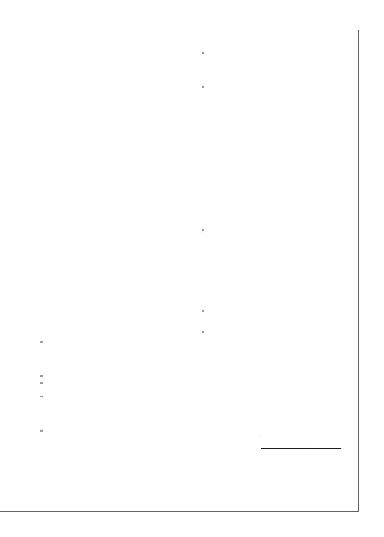
Cable section
To get the full sonic
potential of Cabasse
loudspeakers and
avoid power losses,
the cables connec-
ting the speakers to the power amplifier must have the lowest
possible electrical resistance. To help you in choosing the cor-
rect cable gauge, follow diagram.
Lenght between recommanded
amplifier and loudspeaker section
4,5 m 1,5 mm
2
6 m 2 mm
2
7,5 m 2,5 mm
2
9 m 3 mm
2
12 m 4 mm
2