Behringer XENYX UFX1204 Quick start guide

Category
DJ controllers
Type
Quick start guide
(Visit behringer.com for Full Manual)
Quick Start Guide
XENYX UFX1204
Premium 12-Input 4-Bus Mixer with 16x4 USB/FireWire Interface,
16-Track USB Recorder, XENYX Mic Preamps & Compressors,
British EQs and Multi-FX Processor
2 XENYX UFX1204 Quick Start Guide 3
Important Safety
Instructions
LEGAL DISCLAIMER
Instrucciones de
seguridad
NEGACIÓN LEGAL
GARANTÍA LIMITADA
LIMITED WARRANTY
Terminals marked with this symbol carry
electrical current of su cient magnitude
to constitute risk of electric shock.
Use only high-quality professional speaker cables with
¼" TS or twist-locking plugs pre-installed. Allother
installation or modi cation should be performed only
by quali edpersonnel.
This symbol, wherever it appears,
alertsyou to the presence of uninsulated
dangerous voltage inside the
enclosure-voltage that may be su cient to constitute a
risk ofshock.
This symbol, wherever it appears,
alertsyou to important operating and
maintenance instructions in the
accompanying literature. Please read the manual.
Caution
To reduce the risk of electric shock, donot
remove the top cover (or the rear section).
No user serviceable parts inside. Refer servicing to
quali ed personnel.
Caution
To reduce the risk of  re or electric shock,
do not expose this appliance to rain and
moisture. The apparatus shall not be exposed to dripping
or splashing liquids and no objects  lled with liquids,
suchas vases, shall be placed on the apparatus.
Caution
These service instructions are for use
by quali ed service personnel only.
Toreduce the risk of electric shock do not perform any
servicing other than that contained in the operation
instructions. Repairs have to be performed by quali ed
servicepersonnel.
1. Read these instructions.
2. Keep these instructions.
3. Heed all warnings.
4. Follow all instructions.
5. Do not use this apparatus near water.
6. Clean only with dry cloth.
7. Do not block any ventilation openings. Install in
accordance with the manufacturer’s instructions.
8. Do not install near any heat sources such as
radiators, heat registers, stoves, or other apparatus
(including ampli ers) that produce heat.
9. Do not defeat the safety purpose of the polarized
or grounding-type plug. A polarized plug has two blades
with one wider than the other. A grounding-type plug
has two blades and a third grounding prong. The wide
blade or the third prong are provided for your safety. Ifthe
provided plug does not  t into your outlet, consult an
electrician for replacement of the obsolete outlet.
10. Protect the power cord from being walked on or
pinched particularly at plugs, convenience receptacles,
and the point where they exit from the apparatus.
11. Use only attachments/accessories speci ed by
themanufacturer.
12. Use only with the
cart, stand, tripod, bracket,
or table speci ed by the
manufacturer, orsold with
the apparatus. When a cart
is used, use caution when
moving the cart/apparatus
combination to avoid
injury from tip-over.
13. Unplug this apparatus during lightning storms or
when unused for long periods of time.
14. Refer all servicing to quali ed service personnel.
Servicing is required when the apparatus has been
damaged in any way, such as power supply cord or plug
is damaged, liquid has been spilled or objects have fallen
into the apparatus, the apparatus has been exposed
to rain or moisture, does not operate normally, or has
beendropped.
15. The apparatus shall be connected to a MAINS socket
outlet with a protective earthing connection.
16. Where the MAINS plug or an appliance coupler is
used as the disconnect device, the disconnect device shall
remain readily operable.
17. Correct disposal of this
product: This symbol indicates that
this product must not be disposed
of with household waste,
according to the WEEE Directive
(2012/19/EU) and your national
law. This product should be taken
to a collection center licensed for the recycling of waste
electrical and electronic equipment (EEE). The
mishandling of this type of waste could have a possible
negative impact on the environment and human health
due to potentially hazardous substances that are generally
associated with EEE. At the same time, your cooperation
in the correct disposal of this product will contribute to
the e cient use of natural resources. For more
information about where you can take your waste
equipment for recycling, please contact your local city
o ce, or your household waste collection service.
MUSIC Group accepts no liability for any loss which
may be su ered by any person who relies either
wholly or in part upon any description, photograph,
or statement contained herein. Technical speci cations,
appearances and other information are subject to
change without notice. All trademarks are the property
of their respective owners. MIDAS, KLARK TEKNIK,
TURBOSOUND, BEHRINGER, BUGERA and DDA are
trademarks or registered trademarks of MUSIC Group IP
Ltd. © MUSIC Group IP Ltd. 201 All rights reserved.
For the applicable warranty terms and conditions
and additional information regarding MUSIC Groups
Limited Warranty, please see complete details online at
music-group.com/warranty.
Las terminales marcadas con este símbolo
transportan corriente eléctrica de
magnitud su ciente como para constituir
un riesgo de descarga eléctrica. Utilice solo cables de
altavoz profesionales y de alta calidad con conectores
TS de 6,3 mm o de bayoneta pre jados. Cualquier otra
instalación o modi cación debe ser realizada únicamente
por un técnico cuali cado.
Este símbolo, siempre que aparece,
leadvierte de la presencia de voltaje
peligroso sin aislar dentro de la caja;
estevoltaje puede ser su ciente para constituir un riesgo
dedescarga.
Este símbolo, siempre que aparece,
leadvierte sobre instrucciones operativas
y de mantenimiento que aparecen en la
documentación adjunta. Por favor, lea el manual.
Atención
Para reducir el riesgo de descarga
eléctrica, no quite la tapa (o la parte
posterior). No hay piezas en el interior del equipo que
puedan ser reparadas por el usuario. Si es necesario,
póngase en contacto con personal cuali cado.
Atención
Para reducir el riesgo de incendio o
descarga eléctrica, no exponga este
aparato a la lluvia, humedad o alguna otra fuente que
pueda salpicar o derramar algún líquido sobre el aparato.
Nocoloque ningún tipo de recipiente para líquidos sobre
el aparato.
Atención
Las instrucciones de servicio deben
llevarlas a cabo exclusivamente personal
cuali cado. Para evitar el riesgo de una descarga eléctrica,
no realice reparaciones que no se encuentren descritas
en el manual de operaciones. Lasreparaciones deben ser
realizadas exclusivamente por personalcuali cado.
1. Lea las instrucciones.
2. Conserve estas instrucciones.
3. Preste atención a todas las advertencias.
4. Siga todas las instrucciones.
5. No use este aparato cerca del agua.
6. Limpie este aparato con un paño seco.
7. No bloquee las aberturas de ventilación. Instale el
equipo de acuerdo con las instrucciones del fabricante.
8. No instale este equipo cerca de fuentes de calor
tales como radiadores, acumuladores de calor, estufas u
otros aparatos (incluyendo ampli cadores) que puedan
producir calor.
9. No elimine o deshabilite nunca la conexión a tierra
del aparato o del cable de alimentación de corriente.
Unenchufe polarizado tiene dos polos, uno de los cuales
tiene un contacto más ancho que el otro. Una clavija con
puesta a tierra dispone de tres contactos: dos polos y la
puesta a tierra. El contacto ancho y el tercer contacto,
respectivamente, son los que garantizan una mayor
seguridad. Si el enchufe suministrado con el equipo no
concuerda con la toma de corriente, consulte con un
electricista para cambiar la toma de corriente obsoleta.
10. Coloque el cable de suministro de energía de manera
que no pueda ser pisado y que esté protegido de objetos
a lados. Asegúrese de que el cable de suministro de
energía esté protegido, especialmente en la zona de la
clavija y en el punto donde sale del aparato.
11. Use únicamente los dispositivos o accesorios
especi cados por el fabricante.
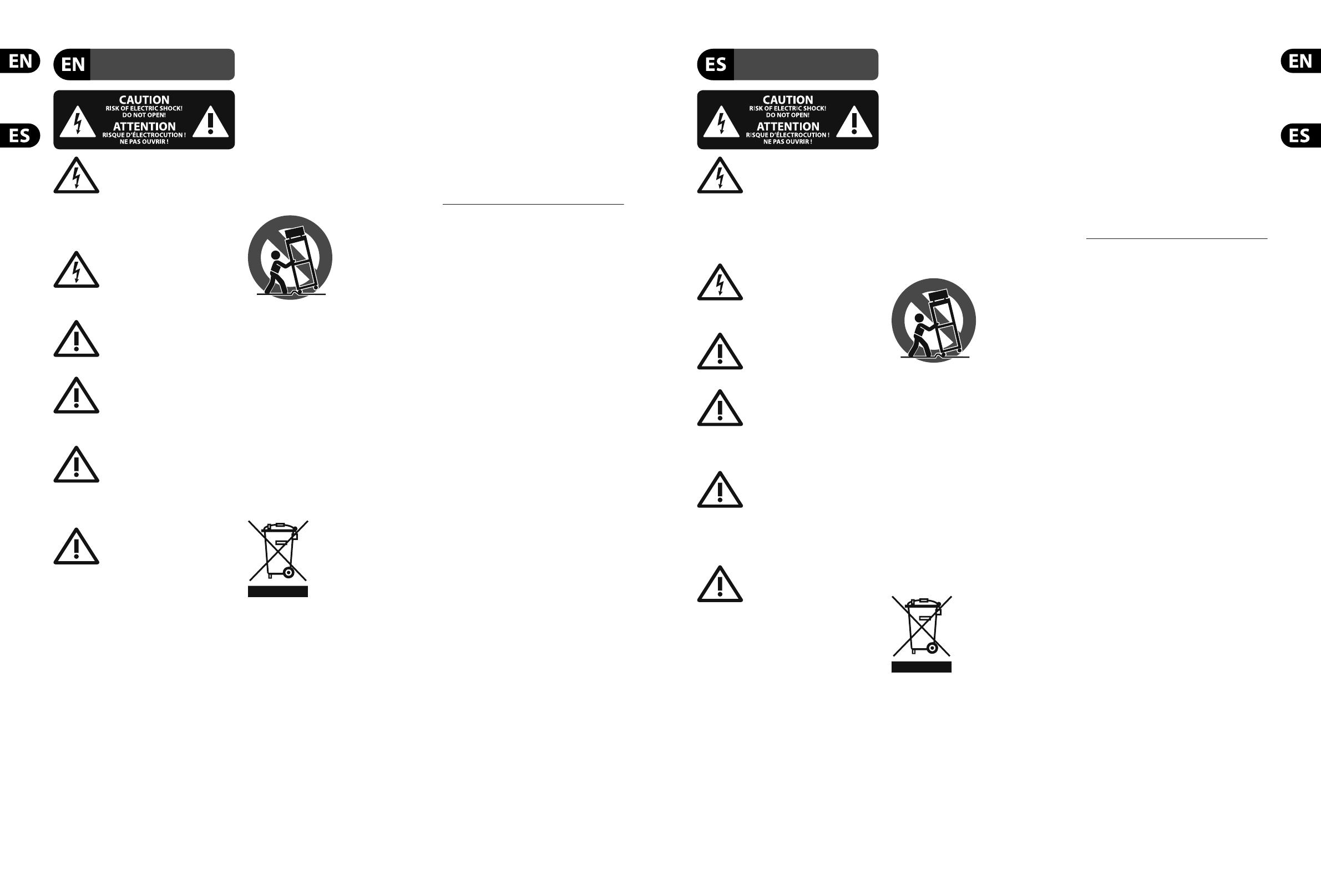
12. Use únicamente la
carretilla, plataforma,
trípode, soporte o mesa
especi cados por el
fabricante o suministrados
junto con el equipo.
Altransportar el equipo,
tenga cuidado para evitar
daños y caídas al tropezar con algún obstáculo.
13. Desenchufe el equipo durante tormentas o si no va a
utilizarlo durante un periodo largo.
14. Confíe las reparaciones únicamente a servicios
técnicos cuali cados. La unidad requiere mantenimiento
siempre que haya sufrido algún daño, si el cable de
suministro de energía o el enchufe presentaran daños,
sehubiera derramado un líquido o hubieran caído objetos
dentro del equipo, si el aparato hubiera estado expuesto
a la humedad o la lluvia, si ha dejado de funcionar de
manera normal o si ha sufrido algún golpe o caída.
15. Al conectar la unidad a la toma de corriente eléctrica
asegúrese de que la conexión disponga de una unión
atierra.
16. Si el enchufe o conector de red sirve como único
medio de desconexión, éste debe ser accesiblefácilmente.
17. Cómo debe deshacerse de
este aparato: Este símbolo indica
que este aparato no debe ser
tratado como basura orgánica,
según lo indicado en la Directiva
WEEE (2012/19/EU) y a las
normativas aplicables en su país.
En lugar de ello deberá llevarlo al punto limpio más
cercano para el reciclaje de sus elementos eléctricos/
electrónicos (EEE). Al hacer esto estará ayudando a
prevenir las posibles consecuencias negativas para el
medio ambiente y la salud que podrían ser provocadas por
una gestión inadecuada de este tipo de aparatos. Además,
el reciclaje de materiales ayudará a conservar los recursos
naturales. Para más información acerca del reciclaje de
este aparato, póngase en contacto con el Ayuntamiento
de su ciudad o con el punto limpio local.
MUSIC Group no admite ningún tipo de responsabilidad
por cualquier daño o pérdida que pudiera sufrir
cualquier persona por con ar total o parcialmente en
la descripciones, fotografías o a rmaciones contenidas
en este documento. Las especi caciones técnicas,
imágenes y otras informaciones contenidas en este
documento están sujetas a modi caciones sin previo
aviso. Todas las marcas comerciales que aparecen
aquí son propiedad de sus respectivos dueños.
MIDAS, KLARK TEKNIK, TURBOSOUND, BEHRINGER,
BUGERA y DDA son marcas comerciales o marcas
registradas de MUSIC Group IP Ltd. © MUSIC Group IP Ltd.
201 Reservados todos los derechos.
Si quiere conocer los detalles y condiciones aplicables
de la garantía así como información adicional sobre la
Garantía limitada de MUSIC group, consulte online toda la
información en la web music-group.com/warranty.
8 9XENYX UFX1204 Quick Start Guide
(EN) Step 1: Hook-Up
(ES) Paso 1: Conexión
(FR) Etape 1 : Connexions
(DE)
Schritt 1: Verkabelung
(PT) Passo 1: Conexões
XENYX UFX1204 Hook-up
(EN) Step 1: Hook-Up
(ES) Paso 1: Conexión
(FR) Etape 1 : Connexions
(DE)
Schritt 1: Verkabelung
(PT) Passo 1: Conexões
Project Studio rear panelProject Studio top panel
TRUTH B3031A TRUTH B3031A
Computer
Drum Machine
V-AMP PRO
B-2 PRO
HPS3000
Electric Guitar
Bass Guitar
Acoustic Guitar
Keyboard
10 11XENYX UFX1204 Quick Start Guide
Live Performance rear panelLive Performance top panel
Bass Guitar
Acoustic Guitar
Keyboard
MP3 Player
F1220AB412DSP B412DSP
XM8500 XM8500
3.5” External USB Drive
XENYX UFX1204 Hook-up
(EN) Step 1: Hook-Up
(ES) Paso 1: Conexión
(FR) Etape 1 : Connexions
(DE)
Schritt 1: Verkabelung
(PT) Passo 1: Conexões
12 13XENYX UFX1204 Quick Start Guide
XENYX UFX1204 Controls
(1)
(4)
(3)
(5)
(6)
(10)
(14)
(8)
(7)
(2)
(9)
(11)
(13)
(16)
(15)
(12)
(19)
(17)
(18)
(20)
Controls
Stereo Inputs
Monitoring/E ects Controls
(21) (22) (23)
(25)
(26)
(24)
(27) (28)
(29)
(30)
(31)
(32)
(33)
(36)
(35)
(34)
Sends and Returns Controls
(44)
(39)
(37)
(38)
(40)
(41)
(42)
(43)
Rear Panel Controls
(46) (47) (48) (49) (50)
(53)(51)(45) (52)
14 15XENYX UFX1204 Quick Start Guide
XENYX UFX1204 Controls
(1) XLR balanced input.
(2) LINE/HI-Z input.
(3) LINE/HI-Z button (Channels 1 & 2 only).
When HI-Z mode is engaged, you can plug
your guitar or bass into this input without
using an external direct (D.I.) box.
(4) +48 V Phantom power is used for condenser
microphones that require between 9 V DC and
48 V DC power to operate.
(5) LOW CUT button  lters out frequencies
below 80 Hz.
(6) GAIN knob adjusts the sensitivity of the MIC
and LINE/HI-Z inputs.
(7) SEND lets you choose to route your input
signal to FireWire/USB pre or post EQ.
(8) COMP(RESSOR) knob adjusts the amount of
compression e ect on the channel.
(9) EQ knobs adjust the HIGH, MID, and LOW
frequencies of the channel. Adjust the FREQ
knob to select the speci c frequency adjusted
by the MID knob.
(10) EQ button turns the EQ section on and o .
(11) AUX / FX knobs adjust how much of the
channel’s signal is sent to the AUX SEND jacks
and/or the internal FX processor.
(12) PAN knob positions the channel’s signal in the
stereo eld.
(13) MUTE button removes the channel from the
MAIN MIX and sends it to the ALT 3-4 bus.
(14) SOLO button sends the channel signal to
the solo bus (Solo in Place) or to the PFL bus
(Pre-Fader Listen).
(15) LEVEL METER shows the input signal level of
the channel’s input signal.
(16) CHANNEL FADER adjusts the channel volume.
(17) LINE IN left and right input jacks for mono or
stereo signals.
(18) LINE/FW 1-2 (3-4) button allows the
signal from a computer to be routed via
FireWire/USB to these channels and controlled
by the EQ and AUX and fader functions.
NOTE: All FireWire (FW) routing switches
work for USB connectivity to a computer and
for the USB stand-alone mode depending
on how you have the MODE selector switch
(48) set.
(19) 4-band EQ for the stereo channels.
(20) BAL(ANCE) knob controls the relative volume
of the left and right input signals before they
are routed to the stereo main mix bus.
(21) CONTROL ROOM OUT jacks carry the summed
e ects and main mix signals, as well as soloed
channel signals.
(22) MAIN OUT jacks for connecting line level signal
to powered speakers or external ampli er.
(23) ALT 3-4 OUT jacks for connecting line
level signal of an alternate stereo mix to
a recording device, powered speakers
or external ampli er. Can also be used
for subgrouping.
(24) CD/TAPE IN and OUT for connecting a stereo
source or for sending the main signal to an
external recorder.
(25) PHONES jacks for connecting headphones.
(26) INPUT level meters display the signal input
intensity going into the FX bus.
(27) FX e ect knob selects which e ect is applied
to the signal.
(28) EDIT knob adjusts the e ects main parameter.
(29) FX ON button turns the e ect on and o .
(30) The TAP/SELECT button performs two
functions. Hit the button several times in the
tempo of the music piece to adapt the delay
time of presets 9 and 15 or the modulation
speed of presets 10-12. The Button will
start  ashing in the corresponding tempo.
The TAP/SELECT button also changes the
characteristic of the second parameter on
presets 1-8, 13-14 and 16. By pressing the
button you can toggle between two di erent
values (light o /on) for the second parameter.
(31) FW/USB LED indicates the computer is
connected (based on the selection switch
on back panel).
(32) VU METER displays the MAIN OUTPUT
signal level.
(33) MODE button determines whether the
SOLO button operates in “Solo in Place”
(button out) or “Pre-Fader Listen”
(button in). PFL is preferred for gain
setting purposes.
(34) PHONES knob controls the volume level of
the PHONES jacks.
(35) CONTROL RM knob controls the volume of the
CONTROL ROOM OUT jacks.
(36) SOURCE monitoring select buttons
route the signal to either the
CONTROL RM/PHONES jacks (left column)
or the MAIN MIX (right column).
(37) PRE/POST fader select buttons for the
AUX and FX SEND busses.
(38) AUX SEND 1-2 knobs adjust the level from
send busses 1-2 (rear panel), internal FX bus
(AUX 2 only), and FW 13-14 channels for
recording (post knob).
(39) Destination routing switch for AUX RETURN 2
(to MAIN bus or AUX SEND 1 bus).
(40) AUX RETURN 1-2 knobs adjust the level of
AUX RETURN busses 1-2 (rear panel) or return
signal from internal FX (AUX 2 only).
(41) MUTE, SOLO, and output LEVEL knobs for
ALT 3-4 bus.
(42) TALKBACK MIC (Built-in), LEVEL knob
(adjusts TALKBACK microphone volume),
DESTINATION switches, and TALK button
(press while talking).
(43) 16 TRACK USB DRIVE RECORDER/MIDI
TRANSPORT CONTROL for use while
connected to a computer via FireWire or
USB as a MIDI Machine Control. Also used
in STAND ALONE MODE for controlling the
internal USB recorder functions.
(44) MAIN MIX stereo fader adjusts the overall
output of the mixer.
(45) POWER ON turns the mixer on.
(46) USB DRIVE jack for use with external USB
hard disk drives (recommended) or thumb
drives in STAND ALONE mode.
(47) USB jack for connecting to a computer.
(48) MODE selector switch.
(49) FireWire jack for connecting to a computer.
(50) CHANNEL INSERTS allow you to connect
external e ects to the individual channels
(1-4) PRE-FADER and PRE-EQ.
(51) MAIN OUTPUTS for sending MAIN MIX via
balanced XLR cables.
(52) AUX(ILIARY) SENDS route the 2 auxiliary bus
signals via balanced or unbalanced ¼" cables.
(53) AUX(ILIARY) RETURNS allow you to bring
a stereo e ects signal routed from an
AUX SEND jack, through a processor,
back into the designated auxiliary bus.
These inputs can also be used to connect
additional line sources such as keyboards.
(EN) Step 2: Controls
24 25XENYX UFX1204 Quick Start Guide
XENYX UFX1204 Getting started
(EN) Step 3: Getting
started
Make sure the power to all devices is
turned o .
Connect all appropriate power, audio and
FireWire/USB cables to the mixer.
Set all faders to the down position,
PAN/BAL knobs centered and all other
knobs (except EQ) all the way left.
Turn the mixer on.
With the MAIN MIX fader, PHONES,
CONTROL RM, and ALT 3-4 knobs all the
way down, turn your PA system or
powered monitors on.
Slowly raise the MAIN MIX fader, PHONES,
CONTROL RM and ALT 3-4 knobs to 0 or
the desired level.
See “Step 4: Gain Setting” for more information.
Adjust the level of connected
microphones and instruments by raising
each CHANNEL FADER.
Adjust the left-right position of a channel
in the stereo  eld if necessary by turning
the channel’s PAN or BAL knob.
Adjust the COMP knob to add
compression to an input if necessary.
For live applications, adjust the overall
output from the mixer to the power
amp or powered speakers by raising the
MAIN MIX fader. If the CLIP LEDs on the
VU METER light, lower the MAIN MIX fader.
Use the channel AUX knobs and master
AUX SEND knob to send the channel
signals to an e ects processor or stage
monitor connected to the AUX SEND jacks. If used
for e ects, route the signal back from the processor
to the AUX RETURN jacks.
EUROLIVE F1320D
active oor monitor
VIRTUALIZER 3D FX2000
26 27XENYX UFX1204 Quick Start Guide
Press the Channel 1 SOLO button.
Press the MODE button under the
VU METER in the main section to allow
the METER to operate in PFL (pre-fader listen) mode.
Sing, Speak, or play at a normal level
through the microphone or instrument
connected to Channel 1.
While singing or playing, turn Channel 1’s
GAIN knob. The VU METER will display
the signal level. Set the GAIN so the
loudest peaks reach 0 on the VU METER. Press the
Channel 1 SOLO button again.
Repeat steps 1-3 for any other channels
that will be used.
Gain Setting Multi-FX Processor
(EN) Step 4: Gain Setting (EN) Step 5: Multi-FX
Processor
Your mixer has a built-in e ects processor.
Follow these steps to add e ects to one or
more channels.
Turn the FX knob up halfway on each
channel you would like to add an
e ect to.
Turn the FX SEND and FX RETURN knobs
to “0”. You may adjust them later.
Make sure the FX ON button is
pushed in.
Scroll through the e ects by turning
the FX knob.
Adjust the intensity of the e ect
turning the edit knob.
If using presets 1-8, 13-14, or 16,
press the TAP/SELECT button to toggle
between two di erent values
(light o /on) for the second parameter. To adjust
the delay time of presets 9 and 15, hit the
TAP/SELECT button several times in the tempo
of the music piece. Similarly, hit the TAP/SELECT
button several times to adjust the modulation
speed of presets 10-12. The button will start
ashing in the corresponding tempo.
Readjust each channel's FX knob to
make sure the right amount of e ect
is added.
28 29XENYX UFX1204 Quick Start Guide
FireWire and USB recording Recording to USB drive in STAND-ALONE mode
(EN) Step 6: FireWire and
USB recording
(EN) Step 7: Recording
to USB drive in
STAND-ALONE
mode
Your mixer is equipped with AD/DA converters,
FireWire and USB connections for sending audio to
and from your computer.
Make sure the drivers for the UFX1204 are
loaded on your windows operating
system (driver is not required for
Mac OS X operating system software).
Connect the mixer to the computer via
FireWire or USB. Make sure you set the
3-way switch on the back panel of the
mixer accordingly.
Select the UFX1204 inputs and
outputs you’d like to use in your
recording software.
Set your desired sample rate and bit
depth from within your DAW
(digital audio workstation) software.
Connect your microphones, instruments,
and line level sources to the
channel inputs. Each channel can be
recorded pre or post EQ as its own mono or stereo
track in your recording software. It is also possible to
record the AUX sends on FireWire channels 13/14.
The MAIN mix can also be recorded on
FireWire channels 15/16.
Arm the tracks in your recording software
and record when ready.
Make sure the STAND ALONE mode is
selected on the back of the mixer
(center position).
When a new USB drive is inserted for
the  rst time, the mixer tests the
writing speed of the drive to determine
the audio quality. The outcome appears on the
TRANSPORT CONTROL screen as “Lo” (16 bit) or
“Hi” (24 bit). If the drive is too slow for recording,
the display will show “SLO” after testing.
If your drive needs to be formatted,
press and simultaneously on
the TRANSPORT CONTROL until the
display reads “For”(blinking). Push to initiate
formatting or to abort.
To show the sample rate setting, push
and hold the TIME REMAIN button until
the sample rate is displayed.
To change the sample rate to 44.1 kHz,
push and hold TIME REMAIN until the
sample rate appears and then
press
while still holding TIME REMAIN.
To change the sample rate to 48 kHz,
push TIME REMAIN until the sample
rate appears and then press
while
holding TIME REMAIN.
With all your microphones,
instruments, and source signals
connected press the
button on the
TRANSPORT CONTROL to create a new folder on the
USB drive with the individual channels as  les.
Congratulations! You are now recording.
Press when  nished.
The recordings are displayed on the
TRANSPORT CONTROL screen as
numbers (1-99).
To toggle between recording and
playlist modes, press TIME REMAIN and
at the same time for two seconds.
To listen or navigate through recordings
you have made, you must be in
recording mode. Playlist mode is ONLY
for playing back WAV  les you copied to your drive
from a PC/Mac.
While in recording mode, press
to hear
what you just recorded. To return to the start,
press the
on the TRANSPORT CONTROL once.
Press twice to move to the previous recording.
Press to move to the start of the
next recording. Note: long push on the or
will not fast forward or rewind within the track.
The MAIN MIX recordings (tracks 15 and 16) will be
played back in the control room section or on
channel 11/12 when the FW 3-4 button is engaged.
To toggle between single playback
and continuous playback mode
(in playlist mode), long press .
To delete the current song in recording
mode, playback or recording must be
stopped. Press and together.
Press to complete deletion or to cancel.
IMPORTANT NOTE: the USB recorder
only plays songs if they are .wav  les
with sample rates of 44.1 or 48.0 kHz
from the folder labeled “MyWav”, no subfolders
are accepted.
30 31XENYX UFX1204 Quick Start Guide
Recording to USB drive in STAND-ALONE mode
(EN) Step 7: Recording
to USB drive in
STAND-ALONE
mode
Using the MIDI CONTROL Features
(EN) Step 8: Using the
MIDI CONTROL
Features
The TRANSPORT CONTROL section on the UFX1204
can operate as a MIDI controller in one of two modes:
STANDARD MIDI MODE or MACKIE CONTROL MODE.
The Mixer must be turned o .
To select STANDARD MIDI MODE, hold
, turn the power on, then release ,
when “Std” shows up in the display.
To select MACKIE CONTROL MODE, hold , turn the
power on, then release , when “MAC” shows up
in the display.
For STANDARD MIDI MODE, map the
transport controls in your recording
software to the TRANSPORT CONTROL
buttons on the UFX1204. In MACKIE CONTROL MODE,
set your recording software to follow the
appropriate protocol.
Transport Control Feature Chart
Show Remaining Time
Press TIME REMAIN short
Show Sampling Rate
Push and hold TIME REMAIN button until the
sample rate is displayed
Select Sampling Rate 44.1 kHz
Push and hold TIME REMAIN until the
sample rate appears and then press
while still
holding TIME REMAIN
Select Sampling Rate 48 kHz
Push TIME REMAIN until the sample rate
appears and then press
while still holding
TIME REMAIN
Toggle PLAY<>PAUSE
Press PLAY (to start) > press PLAY (to pause)
>press PLAY (to continue) > etc.
Toggle Recording Mode (e.g. 001 ) <>
Playlist Mode (e.g. “P01”)
Push TIME REMAIN + for two seconds
Toggle Single Playback ( Pxx ) <>
Continuous Playback ( cxx ) [only in Playlist mode]
Push PLAY for two seconds
FAT-formatting the USB drive*
Press together STOP + for two seconds
Delete current song (in Recording Mode)*
Press together PLAY + for two seconds
*press PLAY to confirm / any other button to abort
Error Codes:
DrP
Dropout while recording. A summary of the total
number of dropouts will be displayed after recording
(e.g. d03).
FSE
File system error. Incompatible  le system on the drive.
Drive must be formatted by the UFX.
oFF No external USB drive is recognized or connected.
SLO
The connected USB drive has been speci ed as
too slow. No recording will be possible.
Although USB sticks and 2.5" USB-powered external drives could work, the use of powered hard drives for direct recording with the internal USB
recorder is recommended.
64 XENYX UFX1204 Quick Start Guide 65
Speci cationsSpeci cations
Mono Inputs
Microphone inputs (XENYX mic preamp) 4
Type
XLR , electronically balanced,
discrete input circuit
Mic E.I.N.
1
(20 Hz - 20 kHz)
@ 0Ω source resistance -129 dB / 131 dB A-weighted
@ 50Ω source resistance -128 dB / 130 dB A-weighted
@ 150Ω source resistance -127 dB / 129 dB A-weighted
Frequency response
<10 Hz – 140 kHz (-1 dB)
<10 Hz – 200 kHz (-3 dB)
Gain range +10 dB to +60 dB
Max. input level +12 dBu @ +10 dB gain
Impedance approx 2.06 kΩ balanced
Signal-to-noise ratio
110 dB A-weighted
(-10 dBu in @ +32 dB gain)
Distortion (THD+N) 0.0045% (-20 dBu in @ +20 dB gain)
Phantom power +48 V, switchable per mic channel
Hi-Z input impedance 1 MΩ
Line Inputs
Type ¼" TRS connector, balanced
Impedance 20 kΩ balanced, 10 kΩ unbalanced
Gain range -10 dB to +40 dB
Max. input level 30 dBu
Stereo Inputs
Type ¼" TRS connector, balanced
Impedance 20 kΩ balanced, 10 kΩ unbalanced
Gain range -20 dB to +20 dB
Max. input level +22 dBu
CD/Tape In
Type RCA connector
Impedance 10 kΩ
Max. input level +22 dBu
EQ Mono Channels
Low 80 Hz / ±15 dB
Mid 100 Hz to 8 kHz / ±15 dB
High 12 kHz / ±15 dB
Low cut 80 Hz,18 dB/oct.
EQ Stereo Channels
Low 80 Hz / ±15 dB
Low mid 300 Hz / ±15 dB
High mid 3 kHz / ±15 dB
High 12 kHz / ±15 dB
Channel Inserts
Type ¼" TRS connector, unbalanced
Max. input level +22 dBu
Crosstalk
Main fader closed 90 dB
Channel muted 88 dB
Channel fader closed 88 dB
Aux Sends
Type ¼" TS connector, unbalanced
Impedance 120 Ω
Max. output level +22 dBu
Aux Returns
Type ¼" TRS connector, balanced
Impedance 20 kΩ balanced, 10 kΩ unbalanced
Max. input level +22 dBu
Main Outputs
Type XLR and 1/4'' TRS balanced
Impedance 240 Ω balanced, 120 Ω unbalanced
Max. output level +28 dBu
Control Room Output
Type ¼" TS connector, unbalanced
Impedance 120 Ω
Max. output level +22 dBu
Dual Phones Output
Type ¼" TRS connector, unbalanced
Max. output level +22 dBu / 23 Ω - 300 mW @ 100 Ω
CD/Tape Out
Type RCA connector
Impedance 1 kΩ
Max. output level +22 dBu
E ects
Converters
24-bit Delta-Sigma,
128-times oversampling
Sampling rate 48 kHz
FireWire/USB Interface
Operation modes FireWire 400 or USB 2.0
Connectors
6-pin FireWire 400 (IEEE1394A),
USB 2.0 Type B
Converters 24-bit
Sample rate 44.1 kHz, 48 kHz, 88.2 kHz, 96 kHz
Channel number 16 x 4 in/out
Operating systems Windows XP or higher, Mac OS X
Low latency audio support ASIO (Win), CoreAudio (Mac)
Transport section MIDI control
Standard MIDI mode
(CC/note commands)
or Mackie control mode
USB Recorder (Stand Alone Mode)
Connector USB 2.0 (Type A)
Storage device
External USB 2.0 hard-disk drive
(operation depends on required
power consumption)
Sample rate 44.1 kHz, 48 kHz
File format WAV (uncompressed)
File system FAT 16 / FAT 32
Number of recorded channels 16 tracks (stored as mono WAV  les)
Power Supply
Mains voltage 100 - 240 V~, 50/60 Hz
Power consumption 60W
Fuse (100 - 230V~, 50/60Hz) T 2A H 250 V
Mains connector Standard IEC receptacle
Physical/Weight
Dimensions (H x W x D) 104 x 329 x 444 mm (4.1 x 13.0 x 17.5")
Weight 4.5 kg (9.9 lbs)
1 Equivalent Input Noise
E ect no. E ect
EDIT
Parameter 1
TAP/SELECT
Parameter 2
TAP/SELECT
LED
1 CATHEDRAL Reverb time Brilliance o /on
2 CONCERT Reverb time Brilliance o /on
3 CLUB Reverb time Brilliance o /on
4 CHAMBER Reverb time Brilliance o /on
5 GOLD PLATE Reverb time Brilliance o /on
6 GATED REV Reverb time Brilliance o /on
7 REVERSE Reverb time Brilliance o /on
8 AMBIENCE Room size Brilliance o /on
9 DELAY No. of repetitions
Time interval
TAP
 a s h i n g
(BPM tempo)
10 CHORUS Intensity
Tempo
TAP
 a s h i n g
(tempo)
11 FL ANGER Intensity
Tempo
TAP
 a s h i n g
(tempo)
12 PHASER Intensity
Tempo
TAP
 a s h i n g
(tempo)
13 ROTARY Intensity Tempo o /on
14 PITCH SHIFT Semi-tone steps (+/-12) Detune o /on
15 DELAY+REV Delay vs. reverb ratio
Time interval
TAP
 a s h i n g
(BPM tempo)
16 CHORUS+REV Chorus vs. reverb ratio Reverb time o /on
FIREWIRE, MAC AND OS X ARE TRADEMARKS OF APPLE INC., REGISTERED IN THE U.S. AND OTHER COUNTRIES.
WINDOWS IS A REGISTERED TRADEMARK OF MICROSOFT CORPORATION IN THE UNITED STATES AND OTHER COUNTRIES.
MACKIE IS A REGISTERED TRADEMARK OF LOUD TECHNOLOGIES INC.
74 XENYX UFX1204 Quick Start Guide 75
Other important information
1. Register online. Please register your new
MUSIC Group equipment right after you purchase it by
visiting behringer.com. Registering your purchase using
our simple online form helps us to process your repair
claims more quickly and e ciently. Also, read the terms
and conditions of our warranty, if applicable.
2. Malfunction. Should your MUSIC Group
Authorized Reseller not be located in your vicinity,
you may contact the MUSIC Group Authorized Ful ller for
your country listed under “Support” at behringer.com.
Should your country not be listed, please check if your
problem can be dealt with by our “Online Support” which
may also be found under “Support” at behringer.com.
Alternatively, please submit an online warranty claim at
behringer.com BEFORE returning the product.
3. Power Connections. Before plugging the
unit into a power socket, please make sure you are using
the correct mains voltage for your particular model.
Faulty fuses must be replaced with fuses of the same type
and rating without exception.
1. Registro online. Le recomendamos que
registre su nuevo aparato MUSIC Group justo después de
su compra accediendo a la página web behringer.com.
El registro de su compra a través de nuestro sencillo
sistema online nos ayudará a resolver cualquier
incidencia que se presente a la mayor brevedad posible.
Además, aproveche para leer los términos y condiciones de
nuestra garantía, si es aplicable en su caso.
2. Averías. En el caso de que no exista un distribuidor
MUSIC Group en las inmediaciones, puede ponerse en
contacto con el distribuidor MUSIC Group de su país,
que encontrará dentro del apartado “Support” de nuestra
página web behringer.com. En caso de que su país no
aparezca en ese listado, acceda a la sección “Online Support”
(que también encontrará dentro del apartado “Support”
de nuestra página web) y compruebe si su problema aparece
descrito y solucionado allí. De forma alternativa, envíenos a
través de la página web una solicitud online de soporte en
periodo de garantía ANTES de devolvernos el aparato.
3. Conexiones de corriente. Antes de enchufar
este aparato a una salida de corriente, asegúrese de que dicha
salida sea del voltaje adecuado para su modelo concreto.
En caso de que deba sustituir un fusible quemado, deberá
hacerlo por otro de idénticas especi caciones, sin excepción.
1. Enregistrez-vous en ligne. Prenez le
temps d’enregistrer votre produit MUSIC Group aussi vite
que possible sur le site Internet behringer.com. Le fait
d’enregistrer le produit en ligne nous permet de gérer
les réparations plus rapidement et plus e cacement.
Prenez également le temps de lire les termes et conditions
de notre garantie.
2. Dysfonctionnement. Si vous n’avez pas de
revendeur MUSIC Group près de chez vous, contactez le
distributeur MUSIC Group de votre pays : consultez la liste
des distributeurs de votre pays dans la page “Support” de
notre site Internet behringer.com. Si votre pays n’est pas
dans la liste, essayez de résoudre votre problème avec
notre “aide en ligne” que vous trouverez également dans
la section “Support” du site behringer.com. Vous pouvez
également nous faire parvenir directement votre demande
de réparation sous garantie par Internet sur le site
behringer.com AVANT de nous renvoyer le produit.
3. Raccordement au secteur. Avant de relier
cet équipement au secteur, assurez-vous que la tension
secteur de votre région soit compatible avec l’appareil.
Veillez à remplacer les fusibles uniquement par des
modèles exactement de même taille et de même valeur
électrique — sans aucune exception.
1. Online registrieren. Bitte registrieren Sie Ihr
neues MUSIC Group-Gerät direkt nach dem Kauf auf der
Website behringer.com. Wenn Sie Ihren Kauf mit unserem
einfachen online Formular registrieren, können wir Ihre
Reparaturansprüche schneller und e zienter bearbeiten.
Lesen Sie bitte auch unsere Garantiebedingungen,
falls zutre end.
2. Funktionsfehler. Sollte sich kein MUSIC Group
Händler in Ihrer Nähe be nden, können Sie den
MUSIC Group Vertrieb Ihres Landes kontaktieren, der auf
behringer. com unter „Support“ aufgeführt ist. Sollte Ihr
Land nicht aufgelistet sein, prüfen Sie bitte, ob Ihr
Problem von unserem „Online Support“ gelöst werden
kann, den Sie ebenfalls auf behringer.com unter
„Support“  nden. Alternativ reichen Sie bitte Ihren
Garantieanspruch online auf behringer.com ein, BEVOR Sie
das Produkt zurücksenden.
3. Stromanschluss. Bevor Sie das Gerät an
eine Netzsteckdose anschließen, prüfen Sie bitte, ob Sie
die korrekte Netzspannung für Ihr spezielles Modell
verwenden. Fehlerhafte Sicherungen müssen ausnahmslos
durch Sicherungen des gleichen Typs und Nennwerts
ersetzt werden.
1. Registre-se online. Por favor, registre seu
novo equipamento MUSIC Group logo após a compra
visitando o site behringer.com Registrar sua compra
usando nosso simples formulário online nos ajuda a
processar seus pedidos de reparos com maior rapidez e
e ciência. Além disso, leia nossos termos e condições de
garantia, caso seja necessário.
2. Funcionamento Defeituoso. Caso seu
fornecedor MUSIC Group não esteja localizado nas
proximidades, você pode contatar um distribuidor
MUSIC Group para o seu país listado abaixo de “Suporte”
em behringer.com. Se seu país não estiver na lista,
favor checar se seu problema pode ser resolvido com o
nosso “Suporte Online” que também pode ser achado
abaixo de “Suporte”em behringer.com. Alternativamente,
favor enviar uma solicitação de garantia online em
behringer.com ANTES da devolução do produto.
3. Ligações. Antes de ligar a unidade à tomada,
assegure-se de que está a utilizar a voltagem correcta para
o modelo em questão. Os fusíveis com defeito terão de
ser substituídos, sem qualquer excepção, por fusíveis do
mesmo tipo e corrente nominal.
Important information
Aspectos importantes
Informations importantes
Weitere wichtige
Informationen
Outras Informações
Importantes
FEDERAL COMMUNICATIONS
COMMISSION COMPLIANCE
INFORMATION
Responsible Party Name: MUSIC Group Services US Inc.
Address: 18912 North Creek Parkway,
Suite 200 Bothell, WA 98011,
USA
Phone Number: +1 425 672 0816
XENYX UFX1204
complies with the FCC rules as mentioned in the followingparagraph:
This equipment has been tested and found to comply with the limits for a ClassB
digital device, pursuant to part 15 of the FCC Rules. These limits are designed
to provide reasonable protection against harmful interference in a residential
installation. This equipment generates, uses and can radiate radio frequency
energy and, if not installed and used in accordance with the instructions, may cause
harmful interference to radio communications. However, there is no guarantee that
interference will not occur in a particular installation. If this equipment does cause
harmful interference to radio or television reception, which can be determined
by turning the equipment o and on, the user is encouraged to try to correct the
interference by one or more of the followingmeasures:
Reorient or relocate the receiving antenna
Increase the separation between the equipment and receiver
Connect the equipment into an outlet on a circuit di erent from that to which the
receiver is connected
Consult the dealer or an experienced radio/TV technician forhelp
This device complies with Part 15 of the FCC rules. Operation is subject to the
following two conditions:
(1) this device may not cause harmful interference, and
(2) this device must accept any interference received, including interference that may
cause undesired operation.
Important information:
Changes or modi cations to the equipment not expressly approved by MUSIC Group
can void the user’s authority to use the equipment.
XENYX UFX1204
We Hear You
1 / 1

Behringer XENYX UFX1204 Quick start guide

Category
DJ controllers
Type
Quick start guide

Ask a question and I''ll find the answer in the document

Finding information in a document is now easier with AI

Ask the document