Rotwerk RB 18 vario User manual
- Category
- Power drills
- Type
- User manual
Page is loading ...

DE
FR
IT
ES
GB
Bedienungsanleitung ................................................................................. 7
Bitte lesen Sie vor der ersten Inbetriebnahme die Bedienungsanleitung
aufmerksam durch, um eine falsche Handhabung zu vermeiden. Bewah-
ren Sie die Anleitung gut auf und geben Sie sie an jeden nachfolgenden
Benutzer weiter, damit die Informationen jederzeit zur Verfügung stehen.
Mode d’emploi ..............................................................................................18
Prière de lire attentivement le mode d’emploi avant la première mise en
service an d’éviter un maniement incorrect. Conservez soigneusement
ces instructions et transmettez-les à tous les utilisateurs suivants an
que les informations se trouvent constamment à disposition.
Istruzioni sull’uso .........................................................................................27
Prima della prima messa in esercizio siete pregati di leggere attentamente
le istruzioni sull’uso per evitare un uso sbagliato. Conservare con cura il
presente manuale d’uso e consegnarlo al successivo utilizzatore prestando
attenzione che sia sempre a disposizione di chi usa l’apparecchio.
Instrucciones de uso................................................................................ 36
Lea estas instrucciones de uso atentamente antes de la primera puesta
en marcha del aparato tanto para garantizar su seguridad como también
la seguridad de terceros. Conserve las instrucciones apropiadamente y
entréguelas al próximo usuario posteriormente, de manera que las infor-
maciones estén disponibles en todo momento.
Instruction Manual .................................................................................... 45
Before initial start-up, please read through these operating instructions
carefully prior to using the machine. Keep the instructions safe and pass
them on to any subsequent user so that the information is always availa-
ble.
28000-20110424
2
28000-20110424
Page is loading ...
Page is loading ...
Page is loading ...
Page is loading ...
Page is loading ...
Page is loading ...
Page is loading ...
Page is loading ...
Page is loading ...
Page is loading ...
Page is loading ...
Page is loading ...
Page is loading ...
Page is loading ...
Page is loading ...
Page is loading ...
Page is loading ...
Page is loading ...
Page is loading ...
Page is loading ...
Page is loading ...
Page is loading ...
Page is loading ...
Page is loading ...
Page is loading ...
Page is loading ...
Page is loading ...
Page is loading ...
Page is loading ...
Page is loading ...
Page is loading ...
Page is loading ...
Page is loading ...
Page is loading ...
Page is loading ...
Page is loading ...
Page is loading ...
Page is loading ...
Page is loading ...
Page is loading ...
Page is loading ...
Page is loading ...

GB-45
GB
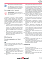
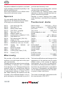
A p p l i c a t i o n s
The benchtop drilling machine RB 18 is desi-
gned for drilling through metal, plastic, wood
and similar materials. The machine must
not be used to process foodstuffs or health-
endangering materials. The drill chuck is de-
signed only for use of drills and tools with a
cylindrical shaft diameter of 1 to 16 mm. The
machine is intended to be used by adults.
The machine may only be used for
the type of work specied, and in
conjunction with the materials cited.
ROTWERK can accept no liability
for loss or damage arising from any
other unauthorised use. Furthermo-
re, such unauthorised use would
also void any warranty claim.
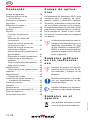
S y m b o l s u s e d i n
t h e s e i n s t r u c t i o n s
Danger signs indicating how to
prevent personal injury or damage
to property.
Essential action sign indicating how
to prevent damage.
Information sign indicating tips on
how to use the machine more ef-
fectively.
S y m b o l s o n t h e m a -
c h i n e
Electrical equipment should not be
thrown out along with the normal
waste.
S a f e t y
When using power tools, the fol-
lowing fundamental safety pre-
cautions must be taken in order
C o n t e n t s
Applications ...........................................45
Symbols used in these instructions .......45
Symbols on the machine .......................45
Safety ....................................................45
Functional elements and controls .......... 48
Assembly ...............................................48
Operation ............................................... 49
Switching on and off ........................... 49
Light ...................................................49
Speed selection..................................49
Setting „slow“ speed...........................49
Setting „fast“ speed ............................50
Handling the quick-grip drill chuck ..... 50
Removing the drill chuck ....................50
Drilling depth indicator........................50
Drilling depth stop .............................. 50
Securing workpieces ..........................50
Dividing attachment ...............................51
Function of dividing attachment ......... 51
Cleaning ................................................51
Maintenance ..........................................51
Changing belts ...................................51
Environmental protection and waste
disposal ............................................51
Spares ...................................................52
Warranty ................................................52
Technical data........................................52
EC Declaration of Conformity ................55
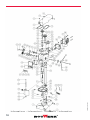
Exploded view .......................................56
Service addresses .................................58

GB-46
27000-20120717
to protect against electric shock,
potential injury and re risk:
Safe work area
• Keeptheworkareaneatandtidy.
Disorder can cause accidents. Do not
leave tools, cables or other items lying
around the work area. Secure your
workstation when leaving it!
• Takeaccountofambientinu-
ences!
Do not expose the machine to rainfall,
and do not operate it in damp or wet
conditions. Provide good lighting. Do
not use the machine where there is a
risk of re or explosion.
• Keepchildrenaway.
Do not let anyone else touch the machi-
ne or the power cable, and keep peo-
ple away from the work area. Children
and youths (with the exception of those
over the age of 16, under supervision)
must not operate the machine. People
unfamiliar with the operation of the ma-
chine must likewise not be allowed to
operate it.
Safe working
• Wearsuitableclothing!
Wear tight-tting clothing and tuck long
hair under a cap or hair net. Do not
wear loose-tting clothing or jewellery,
as it may be caught by moving parts.
• Weargoggles!
Protect your eyes against ying parts.
• Assemblethemachinecorrectly!
All parts must be correctly tted and all
conditions met to ensure trouble-free
operation of the machine.
• Checkthemachinefordamage!
Before starting work, check carefully
that the machine and the guards are in
good working order, there are no slight-
ly damaged parts, and the tool is likewi-
se working properly. Moving parts must
be in perfect working order, and must
not stick. No work must be carried out
on a defective machine. Do not use the
machine if the switch cannot be swit-
ched on and off. Damaged guards and
parts should be repaired or replaced
in the proper manner by an accredited
specialist workshop or aftersales ser-
vice workshop.
• Warning!Rotatingparts!
Wear suitable workwear! Do not wear
loose-tting clothing or jewellery. Never
grasp into rotating workpieces or ma-
chine parts and make sure that artic-
les of clothing and jewellery cannot be
caught in rotating parts. You risk being
injured!
• Warning!Sharpchips!
Never remove chips with your bare
hands. You risk being injured. To remo-
ve chips use a suitable collector. With
the machine switched off, remove chips
using a brush.
• Donotoverloadthemachine!
It will work more efciently and more
safely within its specied capacity ran-
ge. Do not use the machine or the tools
for purposes for which they were not
intended.
• Securethetoolandtheworkpiece!
Make sure the tool and the workpiece
are rmly clamped in place and secu-
red.
• Avoidabnormalbodypostures!
Make sure you are standing steady and
keep your balance at all times.
• Takecare!
Pay attention to what you are doing.
Use common sense. Do not use the
machine if you are lacking concentra-
tion or tired. Working on the machine
is prohibited especially if you are under
the inuence of alcohol, drugs or medi-
cation!
• Unplugtheplugfromthewallsocket!
In the event of faults, when the machi-
ne is not in use, prior to servicing and
GB

GB-47
GB
when changing tools, always switch the
machine off and pull the mains plug.
• Donotleavetoolkeysinserted!
Before switching on the machine, check
that keys and adjusters have been re-
moved.
• Useonlyoriginalparts!
You may risk injury by using accesso-
ries or ancillary equipment other than
recommended in the Technical Manu-
al.
Electrical safety
• Payattentiontothecorrectmains
voltage!
Make sure the mains voltage matches
the specications on the rating plate.
• Useasocketoutletwithagroun-
ding contact!
The machine may only be operated
from a socket outlet with a properly in-
stalled grounding contact.
• Extensioncable
The litz wire cross-section of an exten-
sion cable must be at least 1.0 mm
2
. Al-
ways reel out a cable drum fully before
using it. Check the cable for damage.
• Protectionagainstelectricshock
Avoid body contact with grounded
components (such as pipes, heating
radiators, cookers, refrigerators).
• Dangerfromelectricalenergy!
There is electrical equipment inside the
machine. Regularly check the mains
power cable, the extension cables and
the housings of electrical components.
Have damage repaired by an accredi-
ted electrician.
• Protectthemainspowercable!
Do not use the mains power cable for
purposes for which it was not intended.
Do not use the cable to pull the plug
out of the wall socket. Protect the cable
against heat, oil and sharp edges. Ne-
ver work with a damaged power cable.
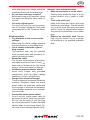
Storage, care and maintenance
• Keepunusedtoolsinasafeplace!
Unused tools should be kept in a dry,
locked location, out of reach of child-
ren.
• Treattoolswithcare!
Keep tools sharp and clean, and keep
handles dry and clean. This will enable
you to work more efciently and more
safely. Follow the maintenance instruc-
tions and the instructions on tool chan-
ging.
• Repairs by specialist staff Repairs
may only be carried out by a specia-
list workshop or by qualied specialist
staff.

GB-48
27000-20120717
GB
F u n c t i o n a l e l e -
m e n t s a n d c o n t r o l s
Overview
A
1 Top cover
2 Emergency-stop switch
3 Light switch
4 ON button
5 OFF button
6 Drilling spindle with MK 2 mount
7 Drill chuck with tapered mandrel MK2 /
B16
8 Plate
9 Plate locking lever
10 Machine base
11 Fixing holes (6x)
12 Cable gland with plastic guard
13 Mains power cable
14 Flange for column attachment
15 Fixing screws (3x)
16 Plate holder
17 Column
18 Drill chuck guard
19 Circlip for drill chuck guard
20 Clamping screw for drill chuck guard
21 Drilling depth stop with scale
22 Motor adjuster lever (speed adjuster)
23 Section table
B
24 Clamp for motor adjuster
25 Motor terminal box
26 Motor
27 Plate height adjuster locking lever
28 Fixing screw (2x) for column attach-
ment
29 Advance knob
30 Drilling head xing screw
C
31 Safety switch
32 Front pulley
33 Intermediate plate
34 Vario drive
35 Vario drive belt
36 V-belt
D
37 Power cable connector
38 Cable wind
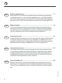
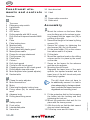
A s s e m b l y
E
1 Mount the column on the base. Make
sure the xing pin in the column is poin-
ting forward and the upper slot (39) is
pointing to the right.
2 Secure the ange to the base by xing
screws (15).
3 Secure the column by tightening the
stud screws (28) (2x) on the sides.
4 Fit the plate holder (16) on the column
from above and x it in place.
5 Fit the plate.
6 Mount the machine head on the drilling
column and x it in place by the screw
on the side.
7 Screw on the levers for the advance
and the motor adjuster.
8 Mounting the drill chuck:
Degrease the taper bore of the work
spindle, the tapered mandrel and the
taper bore of the drill chuck and push
them rmly together.
The drill chuck does not have to
be additionally secured. It is held in
place adequately by the taper attach-
ment, provided the tapers have been
degreased and correctly joined.
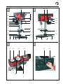
9 Fit the protective disk by rst screwing
the holder into the housing and then
tightening the lock nut.
10 Mount the protective disk and x it in
place with the tommy screw.
11 Afx the circlip so that the disk cannot
drop out when slackened.
12 Fit the top cover and tilt it back.

GB-49
GB
F
13 Slacken the belt and lift out the centre
pulley.
14 Plug the connector in the machine head
into the socket on the upper drilling co-
lumn.
15 Ret the pulleys and belts, close the
top cover and screw it down.
D
16 Place the machine on its side and plug
the mains power cable into the plug on
the underside.
17 Feed the power cable through the ope-
nings provided on the side required,
ensuring the cable is protected by the
rubber plugs.
• For safety, the machine should be bol-
ted on to the workbench.
• Plug the power plug into a grounded
wall socket outlet. The machine is now
ready to run.
O p e r a t i o n
Wear personal protective equipment.
Always wear goggles when working
with the machine, to protect your
eyes from ying parts.
Wear a hair net or cap to prevent your hair
from being caught by rotating parts.
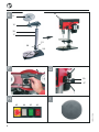
S w i t c h i n g o n a n d o f f
H
• Release the emergency-stop switch
(43) by turning the red knob clockwise.
• Switch on the machine by pressing the
green On switch (45).
• Switch off the machine by pressing the
red Off switch (46).
• In an emergency the machine can be
stopped immediately by pressing the
emergency-stop switch (43).
In an emergency press the emer-
gency-stop switch. The machine
must only be run with the top cover
closed.
L i g h t
• To switch on the built-in working light
press the light switch (44).
• To switch off the built-in working light
press the light switch (44) again.
S p e e d s e l e c t i o n
The speed can be adjusted innitely in two
ranges (fast / slow).
• Switch on the machine (45).
To adjust the Vario speed the mo-
tor must be running.
• Detach the motor clamp (B24) on the
right-hand side.
• Set the speed by adjusting the speed
adjuster lever (A22) on the left-hand
side (1 = slow; 5 = fast)
• Re-attach the motor clamp (B24) on
the right-hand side.
S e t t i n g „ s l o w “ s p e e d
• Switch on the machine and set the Va-
rio speed to 5 (fast).
• Switch off the machine and press the
emergency-stop switch.
• Fit the top cover and tilt it back.
• Slacken the belt by pushing the speed
adjuster lever to 1 (slow).
• Mount the front belt on the upper belt
pair.
• Close the top cover again and screw it
down.
• Release the emergency-stop switch.

GB-50
27000-20120717
GB
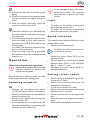
S e t t i n g „ f a s t “ s p e e d
• Switch on the machine and set the Va-
rio speed to 5 (fast).
• Switch off the machine and press the
emergency-stop switch.
• Fit the top cover and tilt it back.
• Slacken the belt by pushing the speed
adjuster lever to 1 (slow).
• Mount the front belt on the lower belt
pair.
• Close the top cover again and screw it
down.
• Release the emergency-stop switch.
H a n d l i n g t h e q u i c k - g r i p
d r i l l c h u c k
• To open the drill chuck hold it by its up-
per xing and turn the chuck clockwi-
se.
• To close and clamp a tool in place hold
the chuck by its upper xing and turn it
anti-clockwise.
Note: Tighten the chuck rmly by hand.
Do not use an implement (such as a
pair of pliers). Otherwise the drill chuck
might be damaged.
R e m o v i n g t h e d r i l l
c h u c k
The drill chuck is driven out of the drilling
spindle using the supplied ejector wedge.
To do so, move the drilling spindle down
until the ejector slot in the side of the spind-
le is visible. Insert the ejector wedge into
the slot and strike it with a hammer to drive
out the drill chuck.
D r i l l i n g d e p t h i n d i c a t o r
G
• A scale indicating the drilling depth is
shown on the axis of the advance knob
(B29). The advance can be read from it
in millimeters.
D r i l l i n g d e p t h s t o p
A
I
• With the machine switched off, move
the drill bit lightly on to the surface of
the workpiece.
• Slacken the drilling depth stop (A21).
by turning the stop handle forward (clo-
ckwise).
• Set the desired drilling depth on the
drilling depth stop scale.
• Re-x the drilling depth stop by turning
the stop handle backward (anti-clock-
wise).
• The work spindle can now only be ad-
vanced as far as the stop limit of the
pre-set drilling depth.
Do not turn the handle beyond the
working depth. Excessive pressu-
re on the advance knob may cause
the pre-set drilling depth to be un-
intentionally altered.
S e c u r i n g w o r k p i e c e s
CAUTION! Workpieces must be
secured against twisting and lif-
ting.
The workpiece may be twisted or pushed
away when tting the drill bit. Also, the spi-
ral shape of the bit may pull the workpiece
upward and so cause it to be spun around.
This may result in serious injury. So the
workpiece must be secured:
• Small workpieces should be clamped in
a suitable machine vice. The vice can be
xed using the grooves in the machine
plate and appropriate xings (screws and
sliding blocks).
• Larger workpieces can be xed directly
on the plate or base using clamp straps.

GB-51
GB
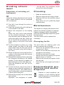
D i v i d i n g a t t a c h -
m e n t
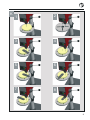
F u n c t i o n o f d i v i d i n g a t -
t a c h m e n t
K
Using the dividing attachment built into the
table, simple divisions can be introduced
into a workpiece:
K1 First drill 4 mm through the centre of
the division.
K2 Insert the centring aid and locating pin
in the middle of the table.
K3 Mount the workpiece on the locating
pin.
Mount the pitch circle mask likewise
on the centred locating pin. The pitch
circle diameter can be adjusted by swi-
velling the plate to the side. When you
do so, the drill bit tip indicates the dia-
meter setting on the pitch circle mask
scale.
K4 Fix the workpiece in place (e.g. using
clamp straps) and take off the pitch
circle mask. Now the rst hole can be
drilled in the pitch circle (drill bit diame-
ter 4 mm).
K5 Remount the pitch circle mask and x it
in place in the newly made hole using a
locating pin (4 mm).
K6 Remove the workpiece xture and rotate
the workpiece according to the desired
division. Fix the division by means of a
third locating pin on the outer table ring.
Rex the workpiece and drill the se-
cond hole.
K7 For the third hole, remove the outer lo-
cating pin and rotate the workpiece on
to the next division. The middle and se-
cond locating pins remain permanently
in place while doing this.
K8 Repeat this process until all holes have
been drilled.
Important: The workpiece is rotated
- not the table. The workpiece rotates
around the centre xing pin.
C l e a n i n g
• Keep the machine clean.
• Remove chips and dirt using a brush.
• Wipe ne dirt from the machine using a
dry cloth.
• Then spray oil on to metallically bright
machine parts.
M a i n t e n a n c e
The machine is largely maintenance-free.
Check the machine regularly for damage.
Replace damaged cables immediately
and have other damage repaired by quali-
ed specialists.
The drive belts must be replaced as
necessary:
C h a n g i n g b e l t s
The drive belts are wearing parts, and
must be replaced as necessary:
• Switch on the machine and set the Va-
rio speed to 5 (fast).
• Switch off the machine and press the
emergency-stop switch.
• Fit the top cover and tilt it back.
• Slacken the belt by pushing the speed
adjuster lever to 1 (slow).
• Remove the old belt and replace it with
the new one.
• Close the top cover again and screw it
down.
E n v i r o n m e n t a l p r o -
t e c t i o n a n d w a s t e
d i s p o s a l
Dispose of used equipment, pa-
ckaging, oil and cleaning agents
with due attention to the protection
of the environment.

GB-52
27000-20120717
GB
Separate cardboard and plastics, and send
such packaging materials separately to an
ofcial collection point.
Send used machines to an ofcial collec-
tion point for electronic scrap.
S p a r e s
You can readily obtain the following
spares from the Rotwerk Service Centre
or through your authorised dealer.
20131 Vario drive belt (76)
20132 Drive belt (71)
20005 Mains power cable
20133 Vario drive, complete
20007 Top cover (75)
20008 Machine plate (12)
20009 Locking lever, complete (7+10)
20010 Plate holder (9)
20134 Drill chuck guard (129-134)
20012 Hinge pin (74)
20013 Front panel with switch (24-30)
20014 Handle bar, vario cpl. (51+52)
20135 Handle bar, tailstock, cpl.
(48+52)
20016 Restoring spring
20017 Plastic cam (2)
20018 Locking lever, lathe (7+10)
20136 Column (117)
W a r r a n t y
We provide a 24-month warranty on the
machine in line with legal and country-spe-
cic requirements.
Damage arising from natural wear and tear,
overloading or improper use is excluded
from warranty cover. Damage arising from
material failure or manufacturing defects
will be rectied free of charge by means
of replacement delivery or repair. For re-
pair under warranty the machine must be
returned to the authorised dealer in its ori-
ginal packaging, accompanied by proof of
purchase and warranty cover.
The drive belts are wearing parts, and are
excluded from warranty cover.
A precondition for meeting claims under
warranty is that the machine has been re-
gularly cleaned and greased.
Damage in transit resulting from inade-
quate packing is excluded from warranty
cover.
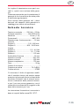
T e c h n i c a l d a t a
Rated voltage .............230 Volts ~ / 50 Hz
Power consumption ..........600 W/S6-40%
Drill chuck ........................... 16 mm (1-16)
Tool mount ................................ MK2, B16
Drilling capacity in steel .................18 mm
Speed
Range 1: ............................310 – 880 rpm
Range 2: .........................900 – 2,400 rpm
Torque
Range 1: .............................. 5.3 – 4.0 Nm
Range 2: .............................. 1.8 – 1.3 Nm
Gap .............................................. 120 mm
Drilling depth ..................................50 mm
Column diameter ........................58,5 mm
Column height ............................. 600 mm
Overall height .............................. 750 mm
Weight ............................................. 29 kg
Protection class ........................................I
Sound pressure ........................74.5 dB(A)
Article number ................................27000
Technical modications and changes to the
appearance of the machine may be made
without notice in the course of ongoing
development. As a result, all dimensions,
information and data presented in these in-
structions are provided with no guarantee
of accuracy. Consequently, no legal claims
can be asserted arising from the informati-
on given in these instructions.
The noise is measured in accordance with
the requirements of EN 12717.
Page is loading ...
Page is loading ...

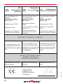
55
Declaraciónde
conformidad CE
CE declaration
of conformity
Hiermit bestätigen wir,
dass die
Taladradora de sobremesa
RB 18 vario
We hereby conrm that the
benchtop drilling machine
RB 18 vario
Número de artículo: 27000 Article number: 27000
A partir del año de construcción 2014 Year of manufacture beginning 2014
corresponde a las siguientes directivas
UE:
conforms to the following relevant EU
Directives:
2004/108 EC • 2006/42 EC • 2006/95 EC
Para garantizar la conformidad, se
aplicaron las siguientes normas
armonizadas, así como las normas:
In order to guarantee consistency, the
following harmonised standards as well as
national standards have been applied:
EN 12717; EN 13128; EN 61029-1
EN 55014-1; EN 55014-2
EN 61000-3-2; EN 61000-3-3
Colocación de la Marca CE 2014
Labelled with CE identication mark in
2014
Rotwerk GmbH
Leopoldstr. 206
DE 80804 München
Deutschland
Christian Meineke (Geschäftsleitung)
GBES

56
27000-20140103
I n f o r m a t i v n o - I n f o r m a t i v n í - I n f o r m a t i v - I n f o r m a t i v e
Page is loading ...

58
27000-20140103
S e r v i c e a d r e s s e n
Rotwerk Service Center
Industriestr. 13
D-51709 Marienheide
Fax: +49/2264/17160
Arnold Winkler
Technischer Grosshandel
Madetswilerstrasse 18
CH-8332 Russikon
Schweiz
Te: +41(0)44 954 83 83
Fax: +41 (0)44 954 83 84
www.arwin.ch
Techno Vis International
9, rue Lino Ventura
F-31470 Fonsorbes
France
Tel. +33 (0) 5 62 23 73 33
Fax +33 (0) 5 62 23 75 55
www.t-v-i.com
DE
CH
FR
Page is loading ...
Page is loading ...
-
 1
1
-
 2
2
-
 3
3
-
 4
4
-
 5
5
-
 6
6
-
 7
7
-
 8
8
-
 9
9
-
 10
10
-
 11
11
-
 12
12
-
 13
13
-
 14
14
-
 15
15
-
 16
16
-
 17
17
-
 18
18
-
 19
19
-
 20
20
-
 21
21
-
 22
22
-
 23
23
-
 24
24
-
 25
25
-
 26
26
-
 27
27
-
 28
28
-
 29
29
-
 30
30
-
 31
31
-
 32
32
-
 33
33
-
 34
34
-
 35
35
-
 36
36
-
 37
37
-
 38
38
-
 39
39
-
 40
40
-
 41
41
-
 42
42
-
 43
43
-
 44
44
-
 45
45
-
 46
46
-
 47
47
-
 48
48
-
 49
49
-
 50
50
-
 51
51
-
 52
52
-
 53
53
-
 54
54
-
 55
55
-
 56
56
-
 57
57
-
 58
58
-
 59
59
-
 60
60


Rotwerk RB 18 vario User manual
- Category
- Power drills
- Type
- User manual
Ask a question and I''ll find the answer in the document
Finding information in a document is now easier with AI
in other languages
- italiano: Rotwerk RB 18 vario Manuale utente
- français: Rotwerk RB 18 vario Manuel utilisateur
- español: Rotwerk RB 18 vario Manual de usuario
- Deutsch: Rotwerk RB 18 vario Benutzerhandbuch
Other documents
-
Scheppach stb t13 User manual
-
Kress 1055 HTC Datasheet
-
Einhell Blue BT-MR 550 Operating instructions
-
-
-
EINHELL BT-BD 701 Owner's manual
-
Fox F12-921A User manual
-
BLACK DECKER KR50RE Owner's manual
-
Ferm TDM1022 User manual
-