Delta 36-5000 Owner's manual

Category
Circular saws
Type
Owner's manual
36-5000
36-5100
36-5052
36-5152
Sierra de mesa de 10 pulgadas
(254 mm) para contratista
Scie de table de 10 pouces
(254 mm) pour entrepreneurs
Instruction Manual
Manuel d’utilisation
Manual de instrucciones
Français (34)
Español (67)
INSTRUCTIVO DE OPERACIÓN, CENTROS
DE SERVICIO Y PÓLIZA DE GARANTÍA.
LÉASE ESTE INSTRUCTIVO
ANTES DE USAR EL PRODUCTO.
www.DeltaMachinery.com
10-INCH CONTRACTOR TABLE SAW
To reduce risk of serious injury, thoroughly read and comply with all warnings and instructions in
this manual and on product.
KEEP THIS MANUAL NEAR YOUR SAW FOR EASY REFERENCE AND TO INSTRUCT OTHERS
TABLE OF CONTENTS
IMPORTANT SAFETY INSTRUCTIONS ................................... 3
Safety Logos ...................................................................... 3
GENERAL POWER TOOL SAFETY RULES ........................... 3
TABLE SAW SAFETY RULES .................................................. 5
POWER CONNECTIONS .......................................................... 7
Power Source ...................................................................... 7
Grounding Instructions ....................................................... 7
Extension Cords .................................................................. 8
UNPACKING ............................................................................. 9
Components and Parts List ................................................ 9
Hardware Package ............................................................ 10
ASSEMBLY .............................................................................. 11
Stand ................................................................................. 11
Fixed Wheels and Stationary Feet .................................... 12
Extension Wings ............................................................... 12
Front and Rear Rails ......................................................... 13
Wood Extension Table ...................................................... 14
Fence Guide and Power Control Box ............................... 14
Throat Plate ....................................................................... 15
Blade and Riving Knife ..................................................... 15
Anti-kickback Pawls .......................................................... 15
Blade Guard ..................................................................... 16
Rip Fence .......................................................................... 16
Miter Gauge ...................................................................... 16
On-Board Storage ............................................................. 16
Adjusting the 90° and 45° Positive Bevel Stops .............. 17
Securing Saw to Floor ...................................................... 17
PREPARING TO CUT .............................................................17
Raising and Lowering the Blade ....................................... 18
Tilting the Blade ................................................................ 18
Selecting and Storing Saw Blades ................................... 19
Changing the Saw Blade .................................................. 19
Riving Knife Position ......................................................... 19
Height Settings .......................................................... 20
Checking Riving Knife Alignment .............................. 20
Using the Miter Gauge ...................................................... 21
Using Blade Guard Assembly ........................................... 21
Checking Fence Alignment .............................................. 21
OPERATION .............................................................................22
Starting and Stopping the Saw......................................... 22
Overload Protection .......................................................... 24
Making Cuts ...................................................................... 23
Rip Cuts .............................................................. 24
Bevel Rip Cuts ..................................................... 24
Cross-Cuts ......................................................... 25
Bevel Cross-Cuts ................................................ 25
Miter Cuts ............................................................ 25
Compound Miter Cuts ......................................... 26
Large Panel Cuts ................................................. 26
Non-Through Cuts ............................................................ 26
Non-through Cuts................................................ 26
Dado Cuts ........................................................... 27
Using Cutting Aids ............................................................ 27
Push Sticks .......................................................... 27
Auxiliary Rip Fence Facing .................................. 28
Auxiliary Miter Gage Facing .............................. 28
Push Blocks ......................................................... 28
Featherboards ..................................................... 29
Cutoff Gauge ....................................................... 29
Jigs ...................................................................... 29
ALIGNMENT ............................................................................30
Riving Knife Alignment With The Blade ............................ 30
Adjusting The Miter Stops ................................................ 30
Aligning Fence Parallel To Miter Slot ................................ 31
Aligning Fence Perpendicular to the Table ....................... 31
240 VOLT SINGLE PHASE OPERATION ................................ 32
MAINTENANCE ....................................................................... 33
TROUBLESHOOTING .............................................................33
ACCESSORIES ........................................................................ 33
WARRANTY ............................................................................. 34
PARTS, SERVICES AND WARRANTY ASSISTANCE ........... 34
REPLACEMENT PARTS .......................................................... 34
FRENCH ................................................................................... 34
SPANISH ................................................................................... 67
2
The DELTA
®
#36-5000 series 10-inch Contractor
Table Saw is designed for portability and high quality
performance. It includes: basic machine, sturdy tubular
steel stand, integral dust chute, a T-Square
®
fence
system, t-slot miter gage, 15-amp induction motor,
on/off switch, cast iron table, extension wings, see-
through blade guard with anti-kickback fingers, and
10-inch carbide blade.
SPECIFICATIONS
Max depth of cut at 90 degrees: 3-½"
Max depth of cut at 45 degrees: 2-½”
Max rip to right of blade: 30" or 52"
Max rip to left of blade: 15"
Max width of dado: 13/16"
MOTOR SPECIFICATIONS:
Amps 15/7.5
Voltage 120/240
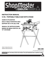
NOTICE: The manual cover illustrates the current production model. All other illustrations contained in the manual
are representative only and may not be exact depictions of the actual labeling or accessories included. They are
intended for illustrative purposes only.
FUNCTIONAL DESCRIPTION
GENERAL POWER TOOL SAFETY RULES
3
continued on page 4
Failure to follow these rules may
result in serious personal injury.
1. READ INSTRUCTION MANUAL AND KNOW YOUR
TOOL. Read and familiarize yourself with entire
instruction manual. Learning the tool’s proper
applications, limitations, and specific potential
hazards will greatly minimize the possibility of
accidents and injury. Make sure all users are familiar
with its warnings and instructions before using tool.
2. KEEP GUARDS AND SAFETY DEVICES IN PLACE
and working properly.
3. REMOVE ADJUSTING KEYS AND WRENCHES.
Form habit of checking to see that all adjusting keys
and wrenches are removed before starting tool.
4. KEEP WORK AREA CLEAN AND WELL LIT.
Cluttered or poorly-lit work areas, surfaces and
benches can lead to accidents.
5. DO NOT USE OR STORE TOOL IN DANGEROUS
ENVIRONMENTS. Exposure to rain and damp or
wet locations can result in shock or electrocution,
or damage the tool. Do not operate electric tools
near flammable liquids or in gaseous or explosive
atmospheres. Motors and switches in these tools
may spark and ignite fumes.
6. KEEP CHILDREN AND BYSTANDERS AWAY from
work area.
7. LOCK TOOLS AND WORK AREA. Use padlocks,
and master switches, or remove and store starter
keys to prevent operation by children and other
unauthorized users.
8. DO NOT FORCE TOOL OR WORKPIECE. Operate
tool at intended speed and feed rate for better and
safer operation.
9. USE PROPER TOOL. Do not force tool to do a task
for which it was not designed.
10. DO NOT ABUSE POWER CORDS. NEVER yank
cord to disconnect from receptacle, crush cord, or
expose it to heat, oil or sharp objects.
11. USE PROPER EXTENSION CORD. If you use an
extension cord, make sure it is in good condition
and heavy enough to carry the current your product
will draw. An undersized cord will cause a drop
in line voltage, resulting in loss of power and
overheating. See Extension Cord Chart for correct
size depending on cord length and data plate
ampere rating. If in doubt, use the next smaller
gauge number. The smaller the gauge number, the
heavier the cord. When working outside, make sure
extension cord is rated for outdoor use. Consult
power connection section of this manual for
Extension Cord Chart and power connection safety.
12. SECURE WORKPIECE. Use clamps or a vise to
hold the workpiece when practical. It is safer than
using your hands and frees both hands to operate
tool.
13. DO NOT OVERREACH. Keep proper footing and
balance to maintain control.
14. MAINTAIN TOOLS WITH CARE. Keep tools
sharp and clean for best and safest performance.
Follow instructions for lubricating and changing
accessories.
15. DISCONNECT TOOL from power source before
servicing, adjusting or changing set-ups or blades,
bits, cutters and other accessories.
16. TO REDUCE RISK OF ACCIDENTAL STARTING,
make sure power switches are in “OFF” position
before plugging tool in.
17. Do not touch the plug’s metal prongs when
unplugging or plugging in the cord.
CAREFULLY READ AND FOLLOW ALL WARNINGS AND INSTRUCTIONS ON YOUR PRODUCT
AND IN THIS MANUAL. SAVE THIS MANUAL. MAKE SURE ALL USERS ARE FAMILIAR WITH ITS
WARNING AND INSTRUCTIONS WHEN USING THE TOOL. Improper operation, maintenance or modification of
tools or equipment could result in serious injury and/or property damage.
If you have any questions or concerns relative to the use of your tool or the contents of this manual, stop using the
tool and contact DELTA
®
Power Equipment Corporation Customer Care at 1-800-223-7278.
SAFETY LOGOS
The definitions below describe the level of severity for each signal word. Please read the manual and pay attention
to these symbols.
Indicates an imminently hazardous situation which, if not avoided, will result in death or serious
injury.
Indicates a potentially hazardous situation which, if not avoided, could result in death or serious
injury.
Indicates a potentially hazardous situation which, if not avoided, may result in minor or moderate
injury.
IMPORTANT SAFETY INSTRUCTIONS
GENERAL POWER TOOL SAFETY RULES
4
SAVE THESE INSTRUCTIONS.
Refer to them often and use them to instruct others.
If tool is loaned to someone, also loan them these instructions.
PROPOSITION 65 WARNING:
Dust created by
power sanding, sawing, grinding, drilling, and other
construction activities may contain chemicals known to
the state of California to cause cancer, birth defects or
other reproductive harm. Some examples are:
Lead from lead-based paints
Crystalline silica from bricks and cement and other
masonry products
Asbestos dust
Arsenic and chromium from chemically-treated
lumber
Your risk from these exposures varies depending on
how often you do this type of work. To reduce your
exposure to these chemicals: work in a well-ventilated
area and work with approved safety equipment, such
as dust masks that are specially designed to filter out
microscopic particles.
18. USE RECOMMENDED ACCESSORIES. Consult
manual for recommended accessories. Use of
inappropriate accessories may cause personal
injury or property damage.
19. NEVER STAND ON TOOL. Serious injury could
occur if the tool tips or if you unintentionally contact
the cutting surface.
20. CHECK TOOLS FOR DAMAGE. Before using,
and after tool or accessory has been dropped or
damaged, check guards and affected parts for
alignment of moving parts, binding of moving
parts, breakage of parts, and any other condition
that may affect its operation to make sure tool will
operate properly and all parts will perform their
intended function. Do not use a damaged product.
A guard or any other part that is damaged should
be properly repaired or replaced using factory-
approved service parts.
21. USE PROPER FEED DIRECTION. Feed workpiece
against the direction of rotation of the tool’s blade,
cutter, or abrasive surface. Feeding in the other
direction may cause the workpiece to be thrown at
high speed.
22. NEVER LEAVE TOOL RUNNING UNATTENDED.
TURN POWER OFF. Do not leave tool until it comes
to a complete stop. In the event of a power failure,
move switch to “OFF” position.
23. STAY ALERT, WATCH WHAT YOU ARE DOING,
AND USE COMMON SENSE. Do not use power
tools when tired or under the influence of drugs,
alcohol, or medication. A moment of inattention
while operating power tools may result in injury.
24. SERVICE PARTS. Use only identical replacement
parts when servicing your tool.
25. WEAR PROPER APPAREL. Do not wear loose
clothing, gloves, neckties, rings, bracelets, or other
jewelry which may get caught in moving parts.
Nonslip protective footwear is recommended. Wear
protective hair covering to contain long hair.
26. WEAR PROPER EYE PROTECTION. All persons
in work area should wear safety glasses with side
shields. Everyday eyeglasses with impact resistant
lenses are not safety glasses. Eye equipment
should comply with ANSI Z87.1 standards.
27. HEARING PROTECTION. All people in work area
should wear proper hearing protection consistent
with noise levels and exposure. Hearing equipment
should comply with ANSI S3.19 standards.
28. DUST PROTECTION. Use of power tools can
generate and/or disburse dust, which may cause
serious and permanent respiratory or other injury,
including silicosis (a serious lung disease), cancer,
and death. Direct particles away from face and
body. Always operate tool in well-ventilated area
and provide for proper dust removal. Use dust
collection system whenever possible. Avoid
breathing dust and avoid prolonged contact with
dust. Allowing dust to get into your mouth or eyes,
or lay on your skin may promote absorption of
harmful material. Use properly fitting NIOSH/OSHA
approved respiratory protection appropriate for the
dust exposure and wash exposed areas with soap
and water.
5
TABLE SAW SAFETY RULES
Failure to follow these rules may result in serious personal injury.
SEE GENERAL POWER TOOL SAFETY SECTION OF THIS MANUAL. Read entire instruction manual before
operating saw. Learning the saw's proper applications, limitations, and specific potential hazards will greatly
minimize the possibility of accidents and injury. Make sure all users are familiar with its warnings and instructions
before using saw.
SEE POWER CONNECTION SECTION OF THIS MANUAL for instructions and warnings regarding power cords and
connections.
TERMINOLOGY
The following terms will be used throughout the manual and you should become familiar with them.
Through-cut refers to any cut that completely cuts
through the workpiece.
Non-through cut refers to any cut that does not
completely cut through the workpiece.
_ Push stick refers to a wooden or plastic stick, usually
homemade, that is used to push a small workpiece
through the saw and keeps the operator’s hands clear
of the blade.
Kickback occurs when the saw blade binds in the cut
or between the blade and the fence and thrusts the
workpiece back toward the operator.
Freehand refers to cutting without the use of a miter
gauge or rip fence or any other means of guiding or
holding the workpiece other than the operator’s hand.
Plunge cutting refers to blind cuts in the workpiece
made by either raising the blade through the workpiece
or lowering the workpiece down to the blade.
Re-sawing – Flipping material to make a cut the saw is
not capable of making in one pass.
Cove cutting – Also known as coving, cove cutting is an
operation where the work is fed at an angle across the
blade.
Failure to follow these rules may result
in serious personal injury.
1. NEVER Perform freehand cutting, plunge cutting,
resawing, or cove cutting.
2. WEAR EYE PROTECTION, appropriate apparel,
hearing protection and dust protection as specified
in the General Power Tool Safety Section of this
manual.
3. USE SAW BLADE GUARD, RIVING KNIFE AND
ANTI-KICKBACK PAWLS. Your saw is equipped
with a modular blade guard, riving knife and
anti-kickback pawl assembly, each component
of which should be used for every possible
operation, including all through cuts. This
assembly is discussed in more detail below. Make
sure components are securely installed prior to
operation.
4. KEEP HANDS AND OTHER BODY PARTS OUT OF
THE BLADE PATH. NEVER have any part of your
body in line with the path of the saw blade.
5. USE A PUSH STICK that is appropriate to the
application to push and hold down a workpiece
through the completion of the cut. A push stick is
a wooden or plastic stick, usually homemade, that
should be used whenever the size or shape of the
workpiece would cause you to place your hands
within 6 in. (152 mm) of the blade. Instructions for
making a push stick are included in this manual.
6. AVOID KICKBACK. Pay particular attention to
instructions (below) for reducing risk of kickback.
7. NO FREEHAND CUTS. Always use a rip fence,
miter gauge, or other appropriate devices to guide
or hold down the workpiece. Use hold-downs, jigs,
fixtures or feather boards to help guide and control
the workpiece. Accessories for use with your saw
are available at extra cost from your local dealer or
authorized service center.
8. DO NOT USE RIP FENCE AND MITER GAUGE AT
THE SAME TIME.
9. DO NOT REACH OVER/REACH AROUND. Never
reach over, in back of, or around the cutting tool
with either hand while the blade is in motion.
10. STABILITY. Make sure table saw is properly
assembled and located on a stable surface before
use to keep saw from moving during cut.
11. PROPER ASSEMBLY. Do not operate this saw until
it is completely assembled and installed according
to the instructions.
12. CHECK WORKPIECE AND SET-UP before
each operation. Knots, irregularities, or nails
in workpiece and positioning mistakes or
incomplete set-up may interfere with or affect saw
performance and personal safety.
13. USE PROPER THROAT PLATE. The proper throat
plate must be in place and properly secured at all
times to reduce the risk of a thrown workpiece and
possible injury.
14. USE CORRECT BLADE AND RIVING KNIFE for the
intended operation. The blade must be installed
so the points of the teeth are pointing toward the
front of the saw. Do not use oversized blade or
blade with incorrect arbor opening. Always tighten
the blade arbor nut securely. Before use, inspect
the blade for cracks or missing teeth. Do not use
a damaged or dull blade. Always use blade within
the thickness range for which the riving knife is
designed.
continued on page 6
6
15. AVOID AWKWARD OPERATIONS AND HAND
POSITIONS where a sudden slip could cause a
hand to move into a saw blade. Operate with table
at or near waist level for maximum balance and
control. Anticipate effect of workpiece size on
your ability to adjust position and maintain control
through completion of cut.
16. KEEP ARMS, HANDS AND FINGERS AT LEAST SIX
INCHES AWAY FROM THE BLADE.
17. NEVER CUT METALS, CEMENT BOARD OR
MASONRY. Certain man-made materials have
special instructions for cutting on table saws.
Follow the manufacturer’s recommendations at all
times.
18. NEVER ATTEMPT TO FREE A STALLED BLADE
OR TRAPPED WORKPIECE without first turning
the machine off and disconnecting the saw from the
power source.
19. NEVER START THE MACHINE WITH THE
WORKPIECE AGAINST THE BLADE to reduce the
risk of a thrown workpiece.
20. NEVER PERFORM LAYOUT, ASSEMBLY OR SET-
UP WORK ON THE TABLE/WORK AREA when the
saw is running.
21. BEFORE LEAVING THE SAW , wait for the blade to
come to a complete stop, then disconnect from the
power source, clean the table and work area, and
lock out switch to prevent unauthorized use.
22. SUPPORT YOUR WORKPIECE based on its size
and the type of operation to be performed. Hold
the work firmly against the fence and down against
the table surface. Do not leave a wide panel or long
board (or other large workpiece) unsupported – the
weight of the board may causes it to shift on the
table resulting in loss of control.
23. AN UNFAMILIAR NOISE OR EXCESSIVE
VIBRATION may indicate a problem with your
saw. If this happens, turn it off and disconnect it
from the power source until the problem has been
located and corrected. Contact customer service
for assistance if the problem cannot be solved.
24. OBTAIN ADVICE from your supervisor, instructor, or
another qualified person if you are not thoroughly
familiar with the operation of this machine.
Knowledge is safety.
SAW BLADE GUARD, ANTI-KICKBACK PAWLS
AND RIVING KNIFE ASSEMBLY
Your table saw is equipped with a blade guard, anti-
kickback pawls and riving knife assembly that covers
the blade and reduces the possibility of accidental
blade contact. The riving knife is a flat plate that fits
into the cut made by the saw blade and effectively
fights kickback by lessening the tendency of the blade
to bind in the cut. Two anti-kickback pawls are located
on the sides of the riving knife that allow the wood
to pass through the blade in the cutting direction but
reduce the possibility of the material being thrown
backwards toward the operator. The blade guard and
anti-kickback pawls can only be used when making
through cuts that sever the wood. When making
rabbets and other non-through cuts, the blade guard
and anti-kickback pawls must be removed and riving
knife lowered to the non-through cut position marked
on the riving knife.
Use all components of the guarding system (blade
guard assembly, riving knife and anti-kickback pawls)
for every operation for which they can be used
including all through-cutting. If you elect not to use
any of these components for a particular application,
exercise additional caution regarding control of the
workpiece, the use of push sticks, the position of
your hands relative to the blade, the use of safety
glasses, the means to avoid kickback and all other
warnings contained in this manual and on the saw
itself. Replace the guarding systems as soon as you
return to through-cutting operations. Keep the guard
assembly in working order.
MAKING A PUSH STICK
In order to operate your table saw safely, you must
use a push stick whenever the size or shape of the
workpiece would otherwise cause your hands to be
within 6 inches (152 mm) of the saw blade or other
cutter. A push stick is included with this saw.
No special wood is needed to make additional push
sticks as long as they are sturdy and long enough
and the wood is free of knots, checks and cracks. A
length of 16 inches (400 mm) is recommended with a
notch that fits against the edge of the workpiece to
prevent slipping. It’s a good idea to have several push
sticks of the same minimum length, 16 inches (400
mm), with different size notches for different workpiece
thicknesses.
The shape can vary to suit your own needs as long as
it performs its intended function of keeping your hands
away from the blade. Angling the notch so the push
stick can be held at a 20- to 30-degree angle from the
saw’s table will help you to hold down the workpiece
while also moving it through the saw. Refer to diagram
in cutting aids section on page 25 of this manual.
TABLE SAW SAFETY RULES (continued)
7
KICKBACKS
Kickbacks can cause serious injury. A kickback occurs
when a part of the workpiece binds between the saw
blade and the rip fence, or other fixed object, and
rises from the table and is thrown toward the operator.
Kickbacks can be avoided by attention to the following
conditions.
HOW TO REDUCE THE RISK OF
KICKBACKS AND PROTECT YOURSELF
FROM POSSIBLE INJURY:
Be certain that the rip fence is parallel to the saw
blade.
DO NOT rip by applying the feed force to the section
of the workpiece that will become the cut-off (free)
piece. Feed force when ripping should always be
applied between the saw blade and the fence; use a
push stick for narrow work, 6 inches (152 mm) wide or
less.
Keep saw blade guard, riving knife and anti-
kickback assembly in place and operating properly.
The riving knife must be in alignment with the saw
blade and the anti-kickback assembly must stop
a kickback once it has started. Check their action
before ripping by pushing the wood under the anti-
kickback assembly. The teeth must prevent the
wood from being pulled toward the front of the saw.
If any part of assembly is not operational, return to
the nearest authorized service center for repair.
Plastic and composite materials (like hardboard) may
be cut on your saw. However, since these are usually
quite hard and slippery, the anti-kickback pawls may
not stop a kickback. Therefore, be especially attentive
to following proper set up and cutting procedures for
ripping.
Use saw blade guard, anti-kickback pawls, and riving
knife assembly for every possible operation, including
all through-cut sawing.
Push the workpiece past the saw blade prior to
releasing control.
NEVER rip a workpiece that is twisted or warped,
or does not have a straight edge to guide along the
fence.
NEVER saw a large workpiece that cannot be
controlled.
NEVER use the fence as a guide or length stop when
crosscutting.
NEVER saw a workpiece with loose knots, flaws, nails
or other foreign objects.
NEVER rip a workpiece shorter than 10 inches (254
mm).
NEVER use a dull blade. A dull blade should be
replaced or re-sharpened.
POWER SOURCE
This saw is equipped with a 15-amp motor for use with
a 120-volt, 60-HZ alternating current. It can be re-wired
for use with a 240-volt power source by a qualified
electrician. See instructions below regarding proper
connections for your saw as wired.
For voltage, the wiring in a shop is as important as
the motor’s rating. A line intended only for lights may
not be able to properly carry the current needed for a
power tool motor; wire that is heavy enough for a short
distance may be too light for a greater distance; and a
line that can support one power tool may not be able to
support two or three.
A separate electrical circuit should be used for your
machines. This circuit should not be less than #12
wire and should be protected with a 20-amp time lag
fuse. If an extension cord is used, use only 3-wire
extension cords which have 3-prong grounding-type
plugs and matching receptacle which will accept the
machine’s plug. Before connecting the machine to the
power line, make sure the switch (s) is in the “OFF”
position and be sure that the electric current is of the
same characteristics as indicated on the machine. A
substantial voltage drop will cause a loss of power and
overheat the motor. It may also damage the machine.
DO NOT EXPOSE THE MACHINE TO RAIN OR OPERATE THE MACHINE IN DAMP LOCATIONS.
POWER CONNECTIONS
GROUNDING INSTRUCTIONS
THIS MACHINE MUST BE GROUNDED WHILE IN USE TO PROTECT THE OPERATOR FROM
ELECTRIC SHOCK.
In the event of a malfunction or breakdown, grounding
provides a path of least resistance for electric current
to reduce the risk of electric shock. This machine is
equipped with an electric cord having a grounding
conductor and a grounding plug. The plug must be
plugged into a matching receptacle that is properly
installed and grounded in accordance with all local
codes and ordinances.
Do not modify the plug as provided on your saw
or as rewired by your electrician. If it will not fit the
receptacle, have the proper receptacle installed by a
qualified electrician.
Improper connection of the equipment-grounding
conductor can result in risk of electric shock. The
conductor with insulation having an outer surface that
is green with or without yellow stripes is the grounding
conductor. If repair or replacement of the electric cord
or plug is necessary, do not connect the equipment-
grounding conductor to a live terminal.
TABLE SAW SAFETY RULES (continued)
8
MINIMUM GAUGE EXTENSION CORD
RECOMMENDED SIZES FOR USE WITH STATIONARY ELECTRIC MACHINES
Ampere
Rating
Volts Total Length of
Cord in Feet
Gauge of
Extension Cord
0-6
0-6
0-6
0-6
240
240
240
240
up to 50
50-100
100-200
200-300
18 AWG
16 AWG
16 AWG
14 AWG
6-10
6-10
6-10
6-10
240
240
240
240
up to 50
50-100
100-200
200-300
18 AWG
16 AWG
14 AWG
12 AWG
10-12
10-12
10-12
10-12
240
240
240
240
up to 50
50-100
100-200
200-300
16 AWG
16 AWG
14 AWG
12 AWG
12-16
12-16
240
240
up to 50
50-100
14 AWG
12 AWG
MINIMUM GAUGE EXTENSION CORD
RECOMMENDED SIZES FOR USE WITH STATIONARY ELECTRIC MACHINES
Ampere
Rating
Volts Total Length of
Cord in Feet
Gauge of
Extension Cord
0-6
0-6
0-6
0-6
120
120
120
120
up to 25
25-50
50-100
100-150
18 AWG
16 AWG
16 AWG
14 AWG
6-10
6-10
6-10
6-10
120
120
120
120
up to 25
25-50
50-100
100-150
18 AWG
16 AWG
14 AWG
12 AWG
10-12
10-12
10-12
10-12
120
120
120
120
up to 25
25-50
50-100
100-150
16 AWG
16 AWG
14 AWG
12 AWG
12-16 120 up to 25 14 AWG
12-16 120 25-50 12 AWG
12-16 120
GREATER THAN 50 FEET NOT RECOMMENDED
Never use a damaged extension cord. Check extension cords before each use. If damaged,
replace immediately. Touching the damaged area could case electrical shock resulting in serious injury.
Keep the extension cord clear of the work area. Position the cord so it will not get caught on lumber,
tools or other obstructions
Use proper extension cords. Make sure your extension cord is a 3-wire extension cord which has a 3-prong
grounding type plug and matching receptacle which will accept the machine’s plug, as described in this manual’s
Grounding Instructions. When using an extension cord, be sure to use one heavy enough to carry the current of the
machine. An undersized cord will cause a drop in line voltage, resulting in loss of power and overheating. The table
below shows the maximum gauge to use depending on the cord length. If in doubt, use the next heavier gauge. The
smaller the gauge number, the heavier the cord. Only round, jacketed cords listed by Underwriter’s Laboratories (UL)
should be used.
Check with a qualified electrician or service personnel
if the grounding instructions are not completely
understood, or if in doubt as to whether the machine is
properly grounded.
Use only 3-wire extension cords that have 3-prong
grounding type plugs and matching, properly grounded
3-conductor receptacles that accept the machine’s
plug, as shown in Figure A, or a properly grounded
receptacle with a grounding means adaptor, as shown
in Figure B.
Repair or replace damaged or worn cord immediately.
IN ALL CASES, MAKE CERTAIN THE RECEPTACLE IN QUESTION IS PROPERLY GROUNDED. IF
YOU ARE NOT SURE, HAVE A qualified ELECTRICIAN CHECK THE RECEPTACLE.
POWER CONNECTIONS
(continued)
This is a grounded, cord-connected tool intended for use on a supply circuit having a nominal voltage of 120 volts.
It is intended to for use on a circuit that has an outlet as shown in FIG. A. It has a plug as shown in FIG A. If you
have a 2 pole receptacle as shown in FIG. B you may use a temporary adapter, as shown in FIG. B. if a properly
grounded outlet is not available. The green ear lug extending from the adapter must be connected to a permanent
grounded outlet box. The temporary adapter should be used only until a properly grounded outlet can be installed
by a qualified electrician.
This tool may be converted to 240 volt power supply circuit by a qualified electrician. If it is converted to 240 volts
it must be equipped with a grounding plug shown in FIG. C and must be connected to an outlet as shown in FIG. C,
which is connected to a permanent ground. No adapter is available or should be used with this tool when converted
to 240 volts.
EXTENSION CORDS
FIG. A
CURRENT
CARRYING
PRONGS
GROUNDING BLADE
IS LONGEST OF THE 3 BLADES
GROUNDED
OUTLET BOX
FIG. B
ADAPTER
GROUNDED OUTLET BOX
GROUNDING
MEANS
FIG. C
Grounding Pin
9
UNPACKING
The machine is heavy, two people are required to
unpack and lift.
Use a safety strap to avoid tip over when lifting
machine.
Prior to tool assembly and use, read this manual
thoroughly to familiarize yourself with proper
assembly, maintenance and safety procedures.
Check shipping carton and machine for damage
before unpacking. Carefully remove components in
top foam layer. Remove the top layer of foam then
remove all components in the bottom layer of foam.
Lay out all parts on a piece of cardboard or other
clean, flat surface. Two or more people are needed to
lift the saw out of the carton. Always check for and
remove protective shipping materials around motors
and moving parts. Do not discard shipping carton and
packing materials until you have carefully inspected the
contents, assembled the machine and are satisfied that
it operates correctly.
Compare package contents to Component Parts List
and Hardware Package List prior to assembly to make
sure all items are present. Carefully inspect parts to
make sure no damage occurred during shipping. If
any parts are missing, damaged or preassembled, do
not assemble. Instead, call DELTA
®
Customer Care at
1-800-223-7278 for assistance.
After assembly remove any protective materials and
coatings from all of the parts and the table saw. The
protective coatings can be removed by spraying
WD-40
®
on them and wiping them off with a soft cloth.
This may need to be redone several times before all of
the protective coatings are removed completely.
After cleaning, apply a good quality paste wax to any
unpainted cast iron surfaces. Make sure to buff out the
wax before assembly.
COMPONENT
PARTS LIST
DESCRIPTION (QTY)
1. Table Saw with attached
Carbide Blade, and Closed-
End Wrench (1)
2. Extension Wing
3. Switch Box (attached to
saw) (1)
4. Tubular Stand (2)
5. Support Panels (4)
6. Fixed Wheels (2)
7. Adjustable Feet (2)
8. Pivoting Pedal and Caster
(not shown) (attached to
saw) (1)
9. Handwheel Handles (2)
(attached to saw)
10. Lock Knobs (2)
11. Miter Gauge (1)
12. Rip Fence Handle (1)
13. Extension Wing (2) with
36-5000 and 5100
(1) with 36-5052 and
36-5152
14. Rip Fence (1)
15. Throat Plate (1)
16. Blade Guard and
Anti-Kickback Pawls
17. Blade (1)
18. Push Stick (1)
1
17
18
16
2
6
5
4
3
14
15
8
Component Callouts
11
7
21
22
23
13
19
10
9
12
20
These contents in
separate carton
19. Rear Rail
20. Fence Guide
21. Front Fence Rail
These contents in separate carton
for 36-5052 and 36-5152 only
22. Wood Table Extension
23. Legs
10
UNPACKING
(continued)
30" Fence versions (36-5000 and 36-5100)
Description Qty. Where used
8mm x 70mm hex head bolt 1 Connect stand halves
m8 nyloc nut 1 Connect stand halves
m6 x 70mm hex bolt 4 connect stand leg to stand
6mm nut 4 connect stand leg to stand
m8 x 53mm axle pin 2 Wheels
m8 locking nut 2 Wheels
m6 x 10mm self tapping screw 16 Stand Panels
5/16-18 x 7/8" Hex Head screw 15 Wings to table 6, wing to wing 3, rear rail 6,
1/4-20 x 5/8 inch button head screw 6 Guid tube to rail
5/16-18 x 1 1/8 inch Flat head screw 8 Front rail to table and wings 8
5/16-18 hex flange nut 25 Wings to table 6, wing to wing 3, rear rail 6, Front rail 8
Rail alignment gauge 1
52" Fence versions (36-5052 and 36-5152)
Description Qty. Where used
8mm x 70mm hex head bolt 1 Connect stand halves
m8 nyloc nut 1 Connect stand halves
m6 x 70mm hex bolt 4 connect stand leg to stand
6mm nut 4 connect stand leg to stand
m8 x 53mm axle pin 2 Wheels
m8 locking nut 2 Wheels
m6 x 10mm self tapping screw 16 Stand Panels
5/16-18 x 7/8" Hex Head screw 15 Wings to table 6, rear rail 6, Wing to wood table 3
5/16-18 Flat washer 3 wing to wood table
1/4-20 x 5/8 inch button head screw 8 Guide tube to rail
5/16-18 x 1 1/8 inch Flat head screw 6 Front rail to table and wings 6
5/16-18 hex flange nut 19 Wings to table 6, rear rail 4, Front rail 6, wing to wood table 3
1/4-20 X 1 1/2 inch Flat Head Screw 12 Rails to wood table
1/4 inch Flat washer 12 Rails to wood table
1/4 inch lock washer 12 Rails to wood table
1/4-20 hex nuts 12 Rails to wood table
#8 x 5/8 inch self tapping screw 8 legs to table
#10-32 by 1 1/2 inch screws 4 legs to table
#10 flat washer 4 legs to table
#10-32 hex nuts 4 legs to table
Rail alignment gauge 1
HARDWARE PACKAGES
11
ASSEMBLY
Do not lift saw without help. Hold it close to your
body while lifting. Keep knees bent and lift with your
legs, not your back.
Fully assemble saw with leg assembly prior to use.
Leg assembly is an integral and necessary part of the
support structure for this saw.
Do not modify saw, or create accessories not
recommended for use with this saw.
Make sure power switch is in “OFF” position before
connecting to power supply.
Do not connect to power supply until assembly is
complete
Slotted screwdriver
Phillips head screwdriver
8mm wrench
10mm wrench
12mm wrench
13mm wrench
3/8-inch wrench
7/16-inch wrench
1/2-inch wrench
9/16-inch wrench
6mm Allen hex wrench
5/32-inch Allen wrench
3/16-inch Allen wrench
TOOLS REQUIRED FOR ASSEMBLY
(not included)
STAND
1. Connect the two tube legs by inserting
the end of the left leg (A) into the end
of the right leg (B) as shown in Figure 1.
Secure with a M8 x 70mm carriage bolt
and nylock nut and hand tighten.
2. Insert the four open ends of the tube
legs into the leg collars (C) as shown.
Secure each leg with a 6mm x 70mm
bolt and nut.
3. Attach the back and front leg support
panels (D) to the legs using four M6 x
12mm self-tapping bolts.
A
Saw Front
D
C
B
FIGURE 1
Avoid contact with blade teeth. Keep
blade stored or lowered when possible.
12
ASSEMBLY
(continued)
A
B
0
1
2
3
4
5
6
7
8
9
10
11
12
INCH
FIXED WHEELS AND STATIONARY FEET
A
B
C
1. Attach the two fixed wheels (A) to the two
left leg, opposite the pivot caster, using the
carriage shoulder bolt as in Figure 2.
2. Screw the adjustable feet (C) into the threaded
inserts in the right leg, next to the pivot caster.
3. Lay a scrap piece of 2x4 in back of the saw, as
shown in Figure 3, to prevent damage to the
dust chute when righting the saw.
4. Stand the saw right side up.
The machine is heavy, two
people are required to stand the
machine up.
5. The two adjustable feet (C) can be raised and
lowered by rotating them. The feet may be
adjusted to level the saw and locked in place
with the locking set screws already assembled
in the frame, using a 6mm allen hex wrench.
See Figure 2.
FIGURE 2
FIGURE 3
FIGURE 4
EXTENSION WINGS
For Models with Three Extension Wings
1. Attach the left side extension wing (A) to the
table using three 5/16-18 x 7/8” hex head
screws.
2. Lay the two remaining wings upside down on
the saw table. Place the side of the wing that
will mount to the saw table near the edge of
the saw table, so that the hole pattern in the
wing matches the hole pattern of the saw. If
you have cast iron wing, it will mount to the
saw table. Place the other wing adjacent to
the wing so the holes patterns match. Fasten
the two wings together using three 5/16-18
x 7/8 inch hex head screws and mating hex
flange nuts.
3. Turn the two wings fastened together (B) over
and fasten them to the saw table using three
5/16-18 x 7/8 inch hex head screws.
4. Make sure the top edges of the wings are flush
with the top of the table and tighten all six
screws.
13
ASSEMBLY
(continued)
C
A
Front
Back
Table
Gauge
Rail
Table
Gauge
Rail
B
FRONT AND REAR RAILS
1. Attach the front rail (A) (2” X 2” X 57” for
the 30” rip capacity models), (2” X 2” X
79” for the 52” rip capacity models), to
the saw table and extension wings using
5/16-18 x 1 1/8inch flat head screws.
Align the holes in the rail with the holes
in the table and extension wings.
2. Use supplied rail alignment gage (B) to
ensure the rail is the proper distance
from the top of the table at each side of
the cast iron table. (fig 6) Then use the
alignment gage to set the same proper
distance for the extension wings.
3. Align the rear rail to the holes in the
rear of the saw table and extension
wings. Attach the rear rail to the saw
table using two 5/16-18 x 7/8 Hex head
screws.
4. Attach the rear rail to the extension
wings using 5/16-18 X 7/8 inch hex head
screws and Hex flange nuts.
5. Use supplied rail alignment gage (B) to
ensure the rail is the proper distance
from the top of the table at each side of
the cast iron table. (fig 6) Then use the
alignment gage to set the same proper
distance for the extension wings.
FIGURE 6
EXTENSION WINGS
For Models with Two Extension
Wings and a Wood Extension Table
1. Attach the left and right side extension
wings (A) to the table using three 5/16-
18 x 7/8” hex head screws for each
wing.
2. Make sure the top edges of the wings
are flush with the top of the table and
tighten all six screws.
3. Proceed to rail assembly.
A
0
1
2
3
4
5
6
7
8
9
10
11
12
INCH
FIGURE 5
14
ASSEMBLY
(continued)
FIGURE 7
FIGURE 8
FIGURE 9
FENCE GUIDE AND POWER CONTROL BOX
1. Connect the fence guide tube (A) by inserting the smaller
end into the larger end. See Figure 10
2. Attach the fence guide to the front rail using four (for
30" versions) six (for 52" versions) 1/4-20 x 1/2-inch hex
button head screws and ¼-inch spring washers
through the holes (B) on the bottom side of
the front rail.
3. Align the two holes in the power
control box bracket with the holes
underneath the front rail (C), located
on the left side of the saw. Secure
the power control box to the front rail
using two1/4-20 x 1/2-inch button
head screws.
4. Fix the hanging power cord at rear side of
front rail by wire clip and M5 x 6mm round
head cross screw.
A
B
C
FIGURE 10
WOOD EXTENSION TABLE
52” rip capacity models only
1. Lay the wood table (A) upside down on floor or
bench.
2. Position legs (B) in corner as shown (fig 7) the
vertical wall of the angle plate on the leg should
be against the end wood wall (C) of the table.
3. Fasten the legs to the table board with (8) #8 x
5/8” self-tapping screws (D).
4. Carefully drill through the holes in the vertical
angle plate holes and the wood wall of the table
with a ¼ inch drill. Feed the #10 by 1 ¾” screws
(E) through the drilled holes from the outside,
then assemble the #10 washers and nuts onto
the screws and tighten.
5. Loosely assemble (3) 5/16-18 x 7/8 inch screws,
washers and nuts (F) into the three holes in the
side of the extension wing as shown. (fig 8)
6. Carefully lower the slotted steel angle table
bracket (G) down onto the screws on the
extension wing. Tighten the screws after the
wood table is leveled with the extension wing.
7. Using the rail alignment gauge (H) adjust the
feet in the legs (I) so the top of the table is at the
proper distance from the rail.
8. Drill ¼ inch holes through the rail holes (J) into
the wood table on the front and back rails. (fig 9)
9. Fasten wood table to rails with ¼-20 X 1 ½ inch
screws, flat washers, lock washers, and nuts.
A
B
E
D
C
F
G
I
H
J
15
ASSEMBLY
(continued)
THROAT PLATE
1. To install throat plate, lower blade below tabletop,
then carefully feed the throat plate, with plate end
first, from the front of the table to the rear, keeping
the blade centered within the slot on the throat
plate. See Figure 11. The plate should rest within
the cavity in the tabletop on top of 5 flat head
screws.
2. Ensure that the throat plate is flush with the top of
the table.
3. If the throat is not flush with the tabletop, adjust
the height of the throat plate using the five set
screws (A) below the throat plate.
NOTE: When installing riving knife, anti-kickback
pawls and blade guard, blade must be at 90° setting
and raised to the maximum height. See Raising and
Lowering Blade, page 18.
BLADE AND RIVING KNIFE
To reduce the risk of serious
personal injury, the riving knife must
be installed and properly positioned for every
possible through and non-through cut.
1. Your saw is shipped with the blade and riving knife
installed and properly aligned. The riving knife
comes installed in the low, non-through cutting
position. Prior to operating your saw, check
to make sure the alignment of the blade to the
A
FIGURE 11
miter slot and the riving knife to the blade was not
affected by shipping. To check alignment of the
blade and riving knife, see page 28 in the Alignment
section of this manual.
2. The riving knife comes installed in the low, non-
through cutting position. To attach the anti-
kickback pawls and blade guard assemblies, the
riving knife must be in the raised position as shown
in Figure 12. To raise and lower the riving knife, see
Riving Knife Height Settings on page 20.
ANTI-KICKBACK PAWLS
To reduce the risk of serious
personal injury, anti-kickback pawls
must be in place when making a through cut.
1. Refer to Figure 12 and locate the anti-kickback
pawls mounting slot (A) in the middle of the top
edge of the riving knife.
2. Slide slot in the middle of the anti-kickback pawls
assembly along the top of the riving knife until the
stem (B) locates the center slot on the riving knife.
3. Depress the stem on the anti-kickback pawls
assembly (B) to allow the assembly to drop
into the slot. Push down on the anti-kickback
pawls assembly until it snaps into place and
locks. Release stem. NOTE: Pull up on the anti-
kickback pawls to make sure it is locked in
place.
A
B
FIGURE 12
ANTI-KICKBACK PAWLS AND BLADE GUARD
To remove the anti-kickback pawls, depress the stem
(B) and pull the anti-kickback assembly off the riving
knife.
16
ASSEMBLY
(continued)
BLADE GUARD
To reduce the risk of serious personal
injury, the blade guard must be in
place when making a through cut.
1. While holding the blade guard assembly (A) in a
vertical position, hook the locating pin (B) at the
back end of the blade guard assembly into the slot
at the back edge of the riving knife.
2. Rotate the blade guard assembly toward the front
of the saw until the metal portion (C) of the blade
guard assembly is parallel to the table as shown in
Figure 13.
3. While holding down on the front of the metal
portion of the guard (C) press the blade guard
lock lever (D) down until it snaps into the locked
position. Check to make sure the guard is locked
onto the riving knife by pulling on the guard. If the
guard is not locked, the blade guard lock lever will
flip up to the unlocked position.
If the metal portion of the blade guard
assembly (C) is not parallel to the
table, the riving knife is not in the raised position.
Remove blade guard assembly and anti-kickback
pawls and raise riving knife, then reinstall the anti-
kickback pawls and the blade guard assembly.
A
B
D
C
FIGURE 13
To remove the blade guard assembly:
1. Lift the blade guard assembly lock lever (D) to the
unlocked position.
2. Rotate the guard back and slide the pin (B) from the
riving knife slot.
RIP FENCE
Attach the handle to the fence cam
The rip fence slides onto the rear fence rail so that the
hook is under the rear rail and rides on the front guide
tube. The fence locks in place by applying pressure in
a downward motion on the rip fence handle. Rip fence
alignment should be checked prior to using your saw.
To check alignment of the rip fence, see alignment
instructions on page 29.
MITER GAUGE
Insert miter gauge into each miter slot to make sure it
slides freely. See Adjusting the Miter Stops section on
page 28 for adjustment of miter gauge accuracy.
ON-BOARD STORAGE
The Delta #36-5000 series contractor table saw
comes with on-board storage for the provided miter
gauge, arbor wrench, push stick and fence. There
is also on-board storage for spare saw blades (sold
separately). The miter gauge, spare blade and arbor
wrench storage areas are located on the right side
panel of the machine and come pre-installed.
On-board storage for the fence and the push stick is
located on the left side of the saw.
17
ASSEMBLY
(continued)
ADJUSTING 90° AND 45° POSITIVE BEVEL STOPS
There are positive stops at each end of the bevel
range. To ensure accurate cuts, the positive stops
must be positioned at exactly at 90° and 45°. The bevel
stops are properly adjusted as shipped. However, for
maximum accuracy, you should check the position
of the stops upon assembly and from time to time to
assure that the settings remain satisfactory. To check
the position of the stops and adjust if necessary, refer
to Figure 14 and do the following.
1. Release the blade tilt lock knob.
2. Rotate the blade tilt handwheel clockwise and tilt the
blade away from, then back toward perpendicular
until the stop is reached the "stop position".
3. Using a carpenter’s square, check the angle of the
blade face to the table, as shown in Figure 20b,
page 20. If the blade is at 90° to the table, proceed
to Step 6.
4. If the blade is not perpendicular to the table, turn
handwheel to slightly tilt the blade away from the
stop position then adjust the 90° stop by rotating
the socket set screw located in the table top
immediately in front of the left side of throat plate
(A). Re-check angle using the carpenter’s square
and continue to adjust until the blade is at 90
degrees when returned to the stop position.
A
B
SECURING SAW TO FLOOR
This saw is designed for portability. Do
not attempt to use the saw to cut a
large or cumbersome workpiece without first taking
appropriate steps to protect against tipping the saw.
Examples of appropriate steps include the use of
support tables and/or securing the saw legs to the floor
by replacing the saw feet with connecting bolts or by
attaching the legs to a floor mounted bracket with
u-straps.
FIGURE 14
5. Rotate the blade tilt wheel counterclockwise until
it rests on the 45° stop. Then repeat Steps 4 and
5, adjusting the 45° stop by rotating the socket set
screw located in front of the right side of the throat
plate. (B)
Failure to comply with the following
warnings may result in serious
personal injury.
ALWAYS
make sure your workpiece is not in contact
with the blade before operating the switch to start
the saw. Blade contact could result in kickback or
thrown workpiece.
To reduce the risk of accidental starting, ALWAYS
make sure the switch is in the off position before
plugging saw into power source.
DO NOT
use blades rated less than the speed of
this tool. Failure to heed this warning could result in
serious personal injury.
Turn unit off and disconnect it from power source
before installing and removing accessories, before
adjusting and when making repairs. An accidental
start-up can cause injury.
Prior to operating the saw, make sure you are familiar
with its features and controls, and have made all
necessary adjustments as described below.
PREPARING TO CUT
18
ASSEMBLY
A
B
FIGURE 15
TILTING THE BLADE
The blade can be tilted up to 45° to the left using the
blade tilt wheel (A) located on the right side panel of
the saw. The angle of tilt is measured by the bevel
gauge on the front of the saw. To tilt the saw blade:
1. Loosen the lock knob (B) counterclockwise and
turn the hand wheel clockwise. A pointer on
the front of the saw indicates the angle of tilt in
½-degree increments.
2. To lock the saw blade at your desired angle, tighten
the lock knob by rotating it clockwise.
A
B
FIGURE 16
PREPARING TO CUT
(continued)
RAISING AND LOWERING THE
BLADE
For most applications, it is recommended that you
raise the blade 1/8-inch (3.2mm) to 1/4-inch (6.4mm)
above the top surface of the workpiece.
Raise or lower the blade with the hand wheel (A)
located on the front of the saw (fig 15).
1. Before raising or lowering the blade, be
sure to loosen the lock knob (B) by turning it
counterclockwise.
2. To raise the saw blade, turn the hand wheel
clockwise. To lower the saw blade, turn the hand
wheel counter-clockwise.
3. Tighten lock knob to keep blade at the desired
height. Only a small amount of force is required to
lock the blade raising mechanism securely. Any
added force merely puts unnecessary strain on the
locking device.
4. When done operating the saw, and when
performing maintenance, adjustments or repairs,
lower blade below surface of table.
19
ASSEMBLY
SELECTING AND STORING SAW BLADES
Riving knives must be matched to saw blade
dimensions in order to function effectively.
The saw blade furnished with your new saw is a
10-inch (254 mm) combination blade, used for cross
cutting (across the grain) and ripping (with the grain)
through the workpiece. The arbor hole of the blade is
5/8-inch (16 mm) diameter. This blade will produce a
good quality cut for most applications.
There are many types of blades available to do specific
and special jobs such as cross cut only, rip only, dado
cuts thin plywood, paneling, etc.
Use only saw blades designed for maximum safe
operating speeds of 3,600 RPM or greater.
Saw blades should always be kept sharp. It is
recommended that you locate a reputable sharpening
service to sharpen your blades when needed.
Never stack blades on top of one another to store.
Place material such as cardboard between them to
keep the blades from coming in contact with one
another, or place them in storage drawer.
Abrasive wheels or blades (including diamond) should
not be used on this saw.
RIVING KNIFE POSITION
NOTE: Safety devices, blade guard assembly and anti-
kickback assembly have been removed in Figure 18 in
order to show the location of specific features. When
operating the saw, these safety devices should be in
place and working properly.
The riving knife is a flat plate that fits into the cut made
by the saw blade and effectively fights kickback by
lessening the tendency of the blade to bind in the cut.
It must be installed and properly positioned for every
through cut and for every non-through cut unless the
riving knife would interfere with the workpiece.
The riving knife thickness (A) must be greater than the
blade body or plate thickness (B) and less than the
kerf or cutting width (C) as shown in Figure 15. The
riving knife provided with this saw is 2.2mm thick and
may be used only with a 10-inch (254mm) blade with
0.102-inch (2.6mm) minimum kerf width and 0.073-inch
(1.8mm) maximum body thickness. Do not attempt to
CHANGING THE SAW BLADE
Use only 10-inch (254 mm) diameter blades with
5/8-inch (16mm) arbor holes, rated at 3,600 rpm or
higher, 0.102-inch (2.6mm) minimum kerf width and
0.073-inch (1.8mm) maximum body thickness.
To reduce the risk of injury, turn unit off and
disconnect it from power source before installing
and removing blades and accessories, before
adjusting and when making repairs. An accidental
start-up can cause injury.
1. Remove the throat plate and raise the saw blade
to its maximum height.
2. Push and hold arbor lock button (A) shown in
Figure 17.
3. Use included arbor wrench to remove the blade
retaining nut and flange (B). Remove old blade.
B
A
FIGURE 17
use this riving knife with blades that are not
within these dimensions.
4. Place the new blade on the arbor
with the teeth pointing down as
the blade rotates toward the
front of the saw table.
5. Replace and tighten the blade
retaining nut and flange.
6. Replace throat plate.
FIGURE 18
A
B
C
PREPARING TO CUT
(continued)
20
PREPARING TO CUT
(continued)
A
Pull Away
to Release
Riving Knife
Upper Position
Detents on Pins
Lower
Position
Detents
Locked
Adjust
RIVING KNIFE HEIGHT
SETTINGS
The height of the riving knife should be adjusted based
on the type of cut being made. For all through cuts
(when the wood is completely severed), it should be
in the raised position, with anti-kickback fingers and
guard installed. For non-through cuts (when the blade
does not penetrate the top of the workpiece), the
riving knife should be in the lowered position and anti-
kickback fingers and guard removed.
TO RAISE OR LOWER THE RIVING KNIFE:
1. Remove throat plate.
2. Raise blade to full height above table.
3. Pull riving knife release lever (A) up to release riving
knife from clamping mechanism. See Figure 19.
4. Push riving knife and release lever to the arbor side
of the blade to disengage riving knife from pins.
a. To adjust the riving knife into the through-cut
position, pull riving knife up to lower detent
pins.
b. To move the riving knife into the non-through
cut position, push it down to upper detent
pins.
NOTE: When adjusting the riving knife up or down, be
sure to pull in a radial motion, as shown.
1. Release lever and pull on riving knife to make sure it
is properly seated in the raised or lowered position.
2. Securely clamp riving knife by pushing riving
knife clamping lever back down to the horizontal
position.
3. Replace throat plate.
DO NOT operate saw unless riving
knife is securely clamped in the raised
position for through-cutting or the lowered position
for non through-cutting.
FIGURE 19
CHECKING RIVING KNIFE
ALIGNMENT
Before connecting the table saw to
the power source and operating the
saw, always inspect the blade guard assembly and
riving knife for proper alignment and clearance with
saw blade. Check the riving knife alignment after
each blade change.
TO CHECK ALIGNMENT:
1. Horizontal Alignment: Lay a
straight edge on the table against
blade face (A) and make sure
it extends out along the
riving knife (B),
as shown
in Figure
20a. The
riving knife
should just
touch the
straight
edge.
Be sure the straight edge
goes between the teeth and
rests on the blade face and
the riving knife for proper
alignment.
A
B
1. Vertical Alignment: Place a carpenter’s square on
the table and against the blade face and make sure
it extends up along the riving knife (B) as shown in
figure 20b. The riving knife and blade should touch
the carpenter’s square with no gaps. Be sure the
straight edge goes between the teeth and rests
on the blade face and the riving knife for proper
alignment.
If the riving knife and blade are out of horizontal or
vertical alignment, refer to riving knife alignment
instructions on page 30 of this manual.
FIGURE 20a
B
FIGURE 20b
  • Page 1 1
  • Page 2 2
  • Page 3 3
  • Page 4 4
  • Page 5 5
  • Page 6 6
  • Page 7 7
  • Page 8 8
  • Page 9 9
  • Page 10 10
  • Page 11 11
  • Page 12 12
  • Page 13 13
  • Page 14 14
  • Page 15 15
  • Page 16 16
  • Page 17 17
  • Page 18 18
  • Page 19 19
  • Page 20 20
  • Page 21 21
  • Page 22 22
  • Page 23 23
  • Page 24 24
  • Page 25 25
  • Page 26 26
  • Page 27 27
  • Page 28 28
  • Page 29 29
  • Page 30 30
  • Page 31 31
  • Page 32 32
  • Page 33 33
  • Page 34 34
  • Page 35 35
  • Page 36 36
  • Page 37 37
  • Page 38 38
  • Page 39 39
  • Page 40 40
  • Page 41 41
  • Page 42 42
  • Page 43 43
  • Page 44 44
  • Page 45 45
  • Page 46 46
  • Page 47 47
  • Page 48 48
  • Page 49 49
  • Page 50 50
  • Page 51 51
  • Page 52 52
  • Page 53 53
  • Page 54 54
  • Page 55 55
  • Page 56 56
  • Page 57 57
  • Page 58 58
  • Page 59 59
  • Page 60 60
  • Page 61 61
  • Page 62 62
  • Page 63 63
  • Page 64 64
  • Page 65 65
  • Page 66 66
  • Page 67 67
  • Page 68 68
  • Page 69 69
  • Page 70 70
  • Page 71 71
  • Page 72 72
  • Page 73 73
  • Page 74 74
  • Page 75 75
  • Page 76 76
  • Page 77 77
  • Page 78 78
  • Page 79 79
  • Page 80 80
  • Page 81 81
  • Page 82 82
  • Page 83 83
  • Page 84 84
  • Page 85 85
  • Page 86 86
  • Page 87 87
  • Page 88 88
  • Page 89 89
  • Page 90 90
  • Page 91 91
  • Page 92 92
  • Page 93 93
  • Page 94 94
  • Page 95 95
  • Page 96 96
  • Page 97 97
  • Page 98 98
  • Page 99 99
  • Page 100 100

Delta 36-5000 Owner's manual

Category
Circular saws
Type
Owner's manual

Ask a question and I''ll find the answer in the document

Finding information in a document is now easier with AI